1
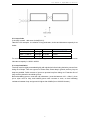
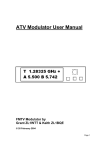
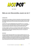
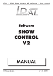
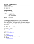
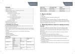
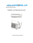
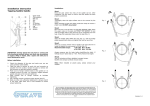
JSPJ1102B Loop Detector
Operational Manual
1. Introduction
Loop detector detects the changes in inductance capacity in the coils, to detect the presence
or absence of vehicle, vehicle signals are converted to relay contact outputs by MCU, other
devices are able to detect whether there is car passing, main application in the parking lot
systems, road and bridge toll system, traffic monitoring systems.
2. Main technical parameters
a)
b)
c)
d)
e)
f)
g)
h)
power supply voltage:AC220±15%V
working environment temperature:-25~65℃
rated power:≦3W
sensitivity: 3 levels adjustable
reaction time:≦500MS
coil inductance:100UH~400UH
connection length:≦5 meters
relative humidity:≦90%
3. Operation
3.1 Installation
The processor should be installed near the loop, waterproof and dry environment, and keep a
certain distance from other devices, (≧20CM,), it is convenient for installation and
maintenance. The working temperature can not be over 65℃. Detecting function, good or bad,
is based on the loops connected. The parameters of loop include: coil material, coil shape,
and correct burying.
3.2 Signal output mode setting
Signal output mode is controlled by coding switch(B2)on control board,detailed definition is
as below, default is OFF state.
User manual of JSPJ1102B loop detector
3.3 Connection sketch map
2
User manual of JSPJ1102B loop detector
Under default code(B2 all are OFF),relay d2’s port 3 and 4,viz. L10 and L9 are level output
mode(press loop output mode),relay d1’s port 5 and 6,viz. L8 and L3 are impulse output
mode(car passing by and arm dropping mode).
3.4 Anti-disturb of adjacent road
Two ways are selected for anti-disturb of adjacent road:(1):add loop circles(add one more
on default circles),this mode is used where 2 loops are nearby. (2):2 processors, select
coding switch(B1)all ON of one processor, after setting this, must power up, diaplasis the
processor, this mode is used where 2 loops have been fixed, disturb of adjacent road is
possible. Ex factory setting is OFF.
Remark:do not set anti-disturb of adjacent road in every project,only when the loops are
close(loop distance <80CM),select this setting.
3.5 State indication
1) green light is state indication:
Slow flash(1S):self detect state; fast flash(100MS):working state;constant bright:there
is a car。
2) red light is fault indication:
Slow flash(1S):circle is too small; fast flash(100MS):circle is too big;constant bright:
loop is not connected or loop is short circuit.
3.6 Sensitivity setting
1) Sensitivity of processor is settled by 3 levels switch on top board:
high(H)、middle(M)、low(L)three levels。
2) default is M,L、M are used for detecting cars, H is used for detecting motorcycle, bicycle
and debugging.
3.7 Debugging method
1) power up,green light flash slow(1S)means it is self detecting,about 3S (more time
needed if there is object moving at the side),after self detecting, green light flash fast
(100MS)means self detection is successful; red light is constant bright, means loop is not
connected or loop is short circuit;,red light flash slow (1S)means circle is too small; red light
flash fast(100MS), means circle is too big;
2) car detection debugging:
When car enters detecting area,working indicator light (green light) stops flashing,constant
3
User manual of JSPJ1102B loop detector
bright,export signal of presence of car; When car leaves detecting area,working indicator
light (green light) flashes,export signal.
4. Loop installation instruction
4.1 Geometry shape for loops
a.rectangle(default),it is better for detection cars and truck.
b. 45 degrees angle,it is better for detecting motorcycle.
c.this shape is used for sliding gate installed nearby.
4
User manual of JSPJ1102B loop detector
d.this shape is used for detecting big scope (a is for lengthways big scope , b is for transverse
big scope)。
a
5
User manual of JSPJ1102B loop detector
b
4.2 Loop circles
If the loop is small,add more circles(BV-2.5).
Take BV-2.5for example,the relation of loop perimeters, circles and inductance capacity is as
below:
Loop perimeter
shape
circles
inductance capacity
3.4m(1.2X0.5)
rectangle
8 circles
2.10 UH
4.6m(1.5X0.8)
rectangle
6 circles
158UH
6m(2X1)
rectangle
5 circles
126 UH
For anomalous shape loops, such as lozenge or “8”,add one more circle,make sure
inductance capacity is 100UH~400UH.
4.3 Loop installation
The loop must be rightly enswathed tightly with spiral tube before being buried to prevent from
being out of shape. Then cut a groove of 10mm wide, 50mm deep in ground, and bury loop as
deep as possible. Polish corners of groove to prevent loop from being cut. Extension line of
loop could be buried in the similar groove.
Before backfilling groove, must test coil inductance ( must be between 100 – 400uH ), then
put a nylon cord on loop, and backfill groove with concrete or resin, so that insulating
resistance between loop and ground is higher than 20MΩ (Over 100 MΩ is better ).
6