1
MLP–Trim
User Manual
0001-0129
Revision B
i
Technical Assistance
If you have comments or questions concerning the operation of the MLP–Trim, please
call us. A member of our Technical Support Staff will be happy to assist you. Ask for
Technical Support: (763) 424-7800 or 1-800-342-4411
Contrex ®
8900 Zachary Lane North
Maple Grove, Minnesota 55369
Copyright © 1999 Contrex
ii
DANGER
Improper installation can
cause severe injury, death or
damage to your system.
Integrate this motion control
unit into your system with
caution.
Operate this motion control unit only under
the conditions prescribed in this manual.
Any other use shall be deemed
inappropriate.
Comply with the National Electrical Code
and all applicable local and national codes.
iii
iv
Table of Contents
Introduction...................................................................... 1-1
Introducing the MLP–Trim ............................................................................. 1-3
Examples of MLP–Trim Applications ............................................................ 1-4
Installation / Setup ......................................................... 2-1
Mounting ........................................................................................................ 2-3
Wiring ............................................................................................................ 2-5
Inputs .................................................................................................... 2-7
Outputs ............................................................................................... 2-15
Serial Communications ...................................................................... 2-17
Calibration .................................................................................................... 2-19
Motor Drive Set Up ............................................................................. 2-20
MLP–Trim Calibration ........................................................................ 2-21
Analog Input Calibration ..................................................................... 2-23
Operation .......................................................................... 3-1
Keypad Operation .......................................................................................... 3-3
Keypad Lockout ............................................................................................. 3-5
Control Parameters ........................................................................................ 3-7
Direct Mode .......................................................................................... 3-8
Master Mode ........................................................................................ 3-9
Follower Mode .................................................................................... 3-19
Offset Mode ........................................................................................ 3-38
Inverse Master Mode ......................................................................... 3-43
Inverse Follower Mode ....................................................................... 3-45
Acceleration/Deceleration .................................................................. 3-47
Tuning ................................................................................................. 3-48
Alarms ................................................................................................ 3-52
Limits .................................................................................................. 3-54
Jog ...................................................................................................... 3-55
Logic Control ................................................................................................ 3-57
Logic Inputs ........................................................................................ 3-58
Logic Outputs ..................................................................................... 3-61
v
Monitor Parameters ..................................................................................... 3-63
Input Monitoring ................................................................................. 3-64
Output Monitoring ............................................................................... 3-67
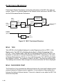
Performance Monitoring ..................................................................... 3-68
Status Monitoring ............................................................................... 3-70
Serial Communications ................................................................................ 3-73
Using Serial Communications ............................................................ 3-74
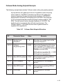
Communications Software Design ..................................................... 3-76
Troubleshooting .............................................................. 4-1
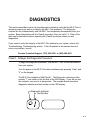
Diagnostics .................................................................................................... 4-3
Troubleshooting ........................................................................................... 4-11
PROM chip Replacement ............................................................................ 4-16
Glossary .............................................................. Glossary-1
Glossary ............................................................................................. Glossary-3
Appendices ......................................................................A-1
Appendix A:
Appendix B:
Appendix C:
Appendix D:
Appendix E:
Appendix F:
Appendix G:
Appendix H:
MLP–Trim Specifications .......................................................... A-1
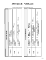
Formulas .................................................................................. B-1
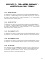
Parameter Summary - numeric quick reference ...................... C-1
Control Parameter Reference .................................................. D-1
Monitor Parameter Reference .................................................. E-1
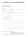
MLP–Trim Fax Cover Sheet ..................................................... F-1
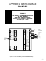
Wiring Diagram Examples ...................................................... G-1
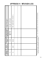
Revision Log ............................................................................ H-1
Warranty .............................................................. Warranty-1
Service Policy .................................................................................... Warranty-3
Warranty ............................................................................................. Warranty-4
Index .......................................................................... Index-1
Index ....................................................................................................... Index-3
vi
List of Illustrations
Figure 1-1
Figure 1-2
Figure 2-1
Figure 2-2
Figure 2-3
Figure 2-4
Figure 2-5
Figure 2-6
Figure 2-7
Figure 2-8
Figure 2-9
Figure 2-10
Figure 2-11
Figure 2-12
Figure 2-13
Figure 2-14
Figure 2-15
Figure 2-16
Figure 2-17
Figure 2-18
Figure 2-19
Figure 2-20
Figure 3-1
Figure 3-2
Figure 4-1
Figure 4-2
Figure 4-3
Figure 4-4
Figure 4-5
Figure G-1
Figure G-2
Figure G-3
Figure G-4
Figure G-5
MLP–Trim Master Mode .......................................................... 1-4
MLP–Trim Follower Mode ......................................................... 1-5
MLP–Trim Cutout Dimensions and Mounting Guide ............... 2-2
MLP–Trim General Wiring Guide ............................................. 2-4
I/O Power (Isolated) .................................................................. 2-7
I/O Power (Non-Isolated) .......................................................... 2-7
AC Power .................................................................................. 2-8
Lead Frequency ....................................................................... 2-8
Feedback Frequency ............................................................... 2-9
Run ........................................................................................... 2-9
Jog .......................................................................................... 2-10
R–Stop .................................................................................... 2-10
F–Stop .................................................................................... 2-11
Master or Follower .................................................................. 2-11
Setpoint Select ........................................................................ 2-12
Scroll Up ................................................................................. 2-13
Scroll Down ............................................................................. 2-13
Analog Input ............................................................................ 2-14
Speed Command Out ............................................................. 2-15
Digital Output 1 and Digital Output 2 ...................................... 2-16
MLP–Trim Multidrop Installation ............................................. 2-17
MLP–Trim Serial Communications Connections .................. 2-18
MLP–Trim Front Panel ............................................................. 3-4
MLP–Trim Internal Structure .................................................. 3-68
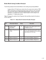
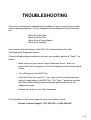
Motor Does Not Stop Flowchart ............................................ 4-12
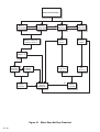
Motor Does Not Run Flowchart ............................................. 4-13
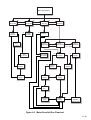
Motor Runs at Wrong Speed Flowchart ................................ 4-14
Motor Runs Unstable Flowchart ............................................ 4-15
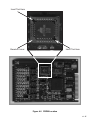
PROM Location ...................................................................... 4-17
MLP–Trim Wiring Connections without Relays ..................... G-1
Relay Start/Stop Wiring Connections .................................... G-2
Start/Stop for Regen with Armature Contactor ...................... G-3
Start/Stop for Non-Regen with Armature Contactor .............. G-4
Two Channel Start/Stop - Lead/Follower Logic ..................... G-5
vii
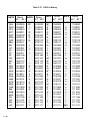
List of Tables
Table 3-1
Table 3-2
Table 3-3
Table 3-4
Table 3-5
Table 3-6
Table 3-7
Table 3-8
Table 3-9
Table 3-10
Table 3-11
Table 3-12
Table 3-13
Table 3-14
Table 3-15
Table 3-16
Table 3-17
Table 3-18
Table 3-19
Table 3-20
Table 3-21
Table 3-22
Table 3-23
Table 3-24
Table 3-25
Table 3-26
Table 3-27
Table 3-28
Table 3-29
Table 3-30
Table 3-31
Table 3-32
Table 3-33
Table 3-34
Table 3-35
viii
Basic Keypad Entry ................................................................. 3-4
Default Direct Mode Control Parameters ................................. 3-8
Entering Direct Mode Control Parameters ............................... 3-8
Default Master Scaling Control Parameters .......................... 3-10
Entering Master Scaling Control Parameters ........................ 3-10
Entering Master Setpoint Control Parameters ....................... 3-11
Master Mode Control Parameters Example .......................... 3-12
Default Scaling Control Parameters ....................................... 3-13
Entering Master Scaling Analog Feedback Parameters ......... 3-14
Master Mode Feedback Allocation Example .......................... 3-15
Default Scaling Control Parameters ....................................... 3-16
Entering Master Scaling Analog Setpoint Parameters ........... 3-17
Master Mode Setpoint Allocation Example ............................. 3-18
Default Follower Scaling Control Parameters ....................... 3-20
Entering Follower Scaling Control Parameters ..................... 3-20
Entering Follower Setpoint Control Parameters .................... 3-21
Follower Mode Control Parameters Example A .................... 3-24
Follower Mode Control Parameters Example B .................... 3-27
Default Scaling Control Parameters ....................................... 3-28
Entering Follower Scaling Analog Lead Parameters .............. 3-29
Follower Mode Lead Allocation Example ............................... 3-30
Default Scaling Control Parameters ....................................... 3-31
Entering Follower Scaling Analog Feedback Parameters ...... 3-32
Follower Mode Feedback Allocation Example ........................ 3-33
Default Scaling Control Parameters ....................................... 3-35
Entering Follower Scaling Analog Setpoint Parameters ......... 3-36
Follower Mode Setpoint Allocation ......................................... 3-37
Default Scaling Control Parameters ....................................... 3-39
Entering Offset Scaling Analog Setpoint Parameters ............. 3-40
Offset Mode Example ............................................................. 3-42
Default Inverse Master Control Parameters ........................... 3-43
Entering Inverse Master Control Parameters ......................... 3-43
Inverse Master Mode Control Parameters Example .............. 3-44
Default Inverse Follower Control Parameters ........................ 3-45
Entering Inverse Follower Control Parameters ...................... 3-45
Table 3-36
Table 3-37
Table 3-38
Table 3-39
Table 3-40
Table 3-41
Table 3-42
Table 3-43
Table 3-44
Table 3-45
Table 3-46
Table 3-47
Table 3-48
Table 3-49
Table 3-50
Table 3-51
Table 3-52
Table 3-53
Table 3-54
Table 3-55
Table 3-56
Table 3-57
Table 3-58
Inverse Follower Mode Control Parameters Example ............ 3-46
Default Master or Follower Accel/Decel Control Parameters 3-47
Entering Master or Follower Accel/Decel Control Parameters 3-47
Default Master or Follower Tuning Control Parameters ........ 3-48
Entering Master or Follower Tuning Control Parameters ...... 3-49
Default Zero Error Loop Control Parameters ......................... 3-50
Entering Zero Error Loop Control Parameters ....................... 3-51
Default Alarm Control Parameters ......................................... 3-52
Entering Alarm Control Parameters ....................................... 3-53
Default Limit Control Parameters ........................................... 3-54
Entering Limit Control Parameters ......................................... 3-54
Default Jog Control Parameters ............................................ 3-55
Entering Jog Control Parameters .......................................... 3-55
Default Drive Enable Logic Control Parameters .................... 3-61
Entering Drive Enable Logic Control Parameters .................. 3-62
Parameter Send - Host Transmission..................................... 3-77
Parameter Send - MLP–Trim Response ................................ 3-80
Control Command Send - Host Transmission ....................... 3-82
Control Command Send - MLP–Trim Response .................... 3-84
Data Inquiry - Host Transmission ........................................... 3-86
Data Inquiry - MLP–Trim Response ...................................... 3-88
ASCII to Binary ...................................................................... 3-90
Binary to Monitor Parameters ................................................ 3-91
ix
–NOTES–
x
Introduction
Introducing the MLP–Trim
Examples of MLP–Trim Applications
1-1
1-2
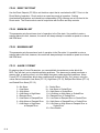
INTRODUCING THE MLP–TRIM
The MLP–Trim is a highly accurate, digital, motor controller. It has advanced
embedded software that is capable of solving a great variety of speed control tasks. It
operates as either a stand-alone control of a single motor (Master mode), as a part of a
complex multi-drive system (Follower mode) or Follower mode with analog trim (Offset
mode).
The MLP–Trim is ideal for motor control applications where your present open loop or
rudimentary closed loop operations are inaccurate or where there is inadequate load
regulation. The MLP–Trim adds accurate digital control to virtually any AC, DC, Servo,
Flux Vector or Clutch drives. The MLP–Trim is also at the forefront in digitally accurate
Follower applications. See Figure 1-1 and Figure 1-2 for examples of Master and
Follower applications.
The MLP–Trim is unique among its competition because the MLP–Trim has
preprogramed software that integrates with your system with little effort from you. The
MLP–Trim will also allow you to enter data that is unique to your system's specific
needs (e.g., maximum RPMs, setpoints, acceleration/deceleration ramp rates). Using
Control Parameters (CPs), this data is entered through either the MLP–Trim's
integrated keypad or though a host computer via the RS485 Serial Communications
port. In addition to the Control Parameters that allow you to customize for your systems
specific needs, the MLP–Trim's Monitor Parameters (MPs) allow you to monitor your
system's performance.
The MLP–Trim's multiple scaling formats allow you to enter the setpoints and monitor
speed in the Engineering Units (e.g., RPMs, gallons per hour, feet per minute) that are
unique to your system. Among the MLP–Trim's advanced capabilities is the flexibility to
preset up to four setpoint entries.
Integrating the MLP–Trim's applied intelligence with your system puts precise speeds
and perfect synchronization at your fingertips, quickly, easily and cost effectively.
1-3
EXAMPLES OF MLP–TRIM
APPLICATIONS
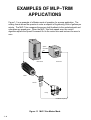
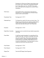
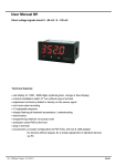
Figure 1-1 is an example of a Master mode of operation for a pump application. The
scaling format allows the operator to enter a setpoint in Engineering Units of gallons per
minute. The MLP–Trim compares the sensor shaft feedback to the scaled setpoint and
calculates any speed error. When the MLP–Trim finds speed error, the control
algorithm adjusts the Speed Command Out to the motor drive and reduces the error to
zero.
Speed
Command
Out
Contrex
CODE
SELECT
SET
POINT
TACH
7
4
1
–
CLEAR
8
5
2
0
9
6
3
.
ENTER
Contrex
Motor Drive
MLP–Trim
Motor
Sensor
Pump
Feedback Frequency
Figure 1-1 MLP–Trim Master Mode
1-4
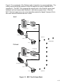
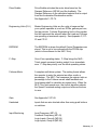
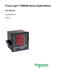
Figure 1-2 is an example of the Follower mode of operation in a pump application. The
scaling format allows the operator to enter the setpoint as a ratio of ingredient B to
ingredient A. The MLP–Trim compares the setpoint ratio to the Follower sensor shaft
feedback and Lead sensor shaft feedback to calculate any speed error. When the
MLP–Trim finds speed error, the control algorithm adjusts the Speed Command Out to
the motor drive and reduces the error to zero.
Lead
Speed
Command
Out
Contrex
CODE
SELECT
SET
POINT
TACH
9
8
7
6
5
4
3
2
1
.
0
–
CLEAR
ENTER
Contrex
Motor Drive
MLP–Trim
Feedback Frequency
Lead Motor
Ingredient A
Sensor
Final Product
Pump
Follower
Speed
Command
Out
Lead Frequency
Contrex
CODE
SELECT
SET
POINT
TACH
Contrex
7
4
1
–
CLEAR
Motor Drive
8
5
2
0
9
6
3
.
ENTER
MLP–Trim
Feedback Frequency
Follower Motor
Sensor
Pump
Ingredient B
Figure 1-2 MLP–Trim Follower Mode
1-5
—NOTES—
1-6
Installation / Setup
Mounting
Wiring
Inputs
Outputs
Serial Communications
Calibration
Motor Drive Setup
MLP–Trim Calibration
Analog Input Calibration
2-1
,,
,
Contrex
TOUT
.03"
( 3C.6U5"
(
3.60"
CUTOUT
3.60"
(3.65"
.03")
DOOR PANEL
Contrex
CODE
SELECT
7
SET
POINT
4
TACH
4.00"
6
5
3
2
1
.
0
–
*6.00"
9
8
CLEAR
ENTER
4.00"
* From the rear of the door panel to the back of the connectors
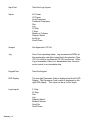
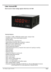
Figure 2-1 MLP–Trim Cutout Dimensions and Mounting Guide
2-2
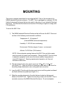
MOUNTING
This section contains instructions for mounting the MLP–Trim in the door panel of a
NEMA Industrial Electrical enclosure. The MLP–Trim is packaged in a compact 1/4 DIN
Vertical Instrument Enclosure that mounts easily in the door of your Industrial Electrical
Enclosure. The Electrical Enclosure must have an IP54 rating or higher to comply with
CE installations.
To mount the MLP–Trim:
1) The NEMA Industrial Electrical Enclosure that will house the MLP–Trim must
conform to the following environmental conditions:
Temperature: 0 - 55 degrees C
(Internal NEMA enclosure temperature)
Humidity: 0 - 95% RH non-condensing
Environment: Pollution degree 2 macro - environment
Altitude: To 3300 feet (1000 meters)
NOTE: Allow adequate spacing between the MLP–Trim and other equipment to provide for proper heat convection. Placing the MLP–Trim too close
to adjacent equipment could cause the interior ambient temperature to
exceed 55 degrees C. Spacing requirements depend on air flow and
enclosure construction.
2) The dimensions for the door panel cutout are 3.65"+ .03" x 3.65 +.03"
(see Figure 2-1). Allow two inches of clearance on all sides of the cutout for
mounting clamp attachments, wire routing and heat convection.
3) Insert the MLP–Trim through the door panel cutout until the gasket and bezel
are flush with the door panel (see Figure 2-1).
4) Slide the mounting clamps into the slots that are located on the top and
bottom of the MLP–Trim. Tighten the mounting screws until the MLP–Trim is
mounted securely in the NEMA Electrical Enclosure. Do not overtighten.
2-3
2
TD/RD–
2
* Neut or L2
GND
PE
NEUT
L1
R1
11
10
9
8
14
15
16
17
V_DO
DIG_OUT1
DIG_OUT2
COM
18
19
ANAL_IN
COM
J6
13
COM
SCRL_DWN 12
SCRL_UP
SETPT
MST/FOL
COM
R2
COM
50V
MAX
+V
R-Stop
F–STOP
External
DC Power
Supply
Master/
Follower
Setpoint
Select
Scroll Up
Scroll Down
F-Stop
Jog
6
R–STOP
7
Run
5
JOG
4
Feedback
Frequency
Sensor
Lead
Frequency
Sensor
RUN
+5V
SIG
COM
+5V
SIG
COM
3
2
FDBK_FQ
+5V COM
+5VDC External
DC Power
Supply
COM
1
LEAD_FQ
1
2
J5
COM
5V_DI
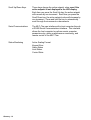
Figure 2-2 MLP–Trim General Wiring
model # 3200-1936
Use 230 VAC with MLP-Trim model # 3200-1937
AC
POWER
* Use 115 VAC with MLP-Trim
3
J4
1
SPD
CMD
GND/PE
DRV_SIG
2 DRV_COM
J3
1
L1
Fuses
1A
250V
COM
SIG
Motor Drive
T/R–
T/R+
3 COM_AUX
J2
1
COM
5V
2 COM_AUX
TD/RD+
RS485 Serial
Communications
J1
1
I/O
PWR
FREQ
INPUTS
DIGITAL
INPUTS
DIGITAL
OUTPUTS
2-4
RS485
COMM
ANAL
IN
AUX
PWR
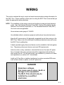
WIRING
This section contains the input, output and serial communications wiring information for
the MLP–Trim. Please read this section prior to wiring the MLP–Trim to ensure that you
make the appropriate wiring decisions.
NOTE: The installation of this motor control must conform to area and local electrical
codes. See The National Electrical Code (NEC,) Article 430 published by the
National Fire Protection Association, or The Canadian Electrical Code (CEC).
Use local codes as applicable.
Use a minimum wire gauge of 18 AWG.
Use shielded cable to minimize equipment malfunctions from electrical noise.
Keep the AC power wiring (J4) physically separated from all other wiring on the
MLP–Trim. Failure to do so could result in additional electrical noise and cause
the MLP–Trim to malfunction.
A hand operated supply disconnect device must be installed in the final application. The primary disconnect device must meet EN requirements.
Inductive coils on relay, contactors, solenoids that are on the same AC power
line or housed in the same enclosure should be suppressed with an RC network across the coil. For the best results, use resistance (r) values of 50 ohms
and capacitance (c) values of 0.1 microfarads.
Install an AC line filter or isolation transformer to reduce excessive EMI noise,
such as line notches or spikes, on the AC power line.
DANGER
Hazardous voltages.
Can cause severe injury, death or
damage to the equipment.
The MLP–Trim should only be
installed by a qualified
electrician.
2-5
–NOTES—
2-6
INPUTS
NOTE: The installation of this motor control must conform to area and local electrical
codes. See The National Electrical Code (NEC,) Article 430 published by the
National Fire Protection Association, or The Canadian Electrical Code (CEC).
Use local codes as applicable.
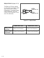
I/O Power (J5 pins 1, 2)
For isolated operations, the
Frequency Inputs (J6 pins 1, 2, 3),
the Digital Inputs (J6 pins 4-13 ), the
Digital Outputs (J6 pins 14-17) and
Analog Input (J6 pins 18,19) require
an external source of +5VDC power.
CAUTION: The MLP-Trim is
shipped from the factory nonisolated with J1 and J5 jumpers.
You must remove the J1 and J5
jumpers before you connect the
External Power Supply or you can
damage the equipment. The
external supply should be free of
ripple and noise to prevent
analog signal bounce. Do not
exceed +5VDC on the I/O Power
input.
Use the Auxiliary Power Output
(J1 pins 1, 2) to supply power to
non-isolated operations. The
MLP-Trim is shipped from the
factory with the wiring in the nonisolated operation.
NOTE: The MLP-Trim should be
wired in the isolated mode
when using the analog
input for precision applications (setpoint or
frequency replacement).
References: Appendix A,
MLP–Trim Specifications.
1
+5V
2
COM
+5VDC *
External
Power
Supply
J5
* Do not connect the External Power Supply
Common to Earth Ground.
Figure 2-3 I/O Power / Isolated
1
2
+5V
COM_AUX
J1
1
2
J5
Figure 2-4 I/O Power / Non-Isolated
2-7
AC Power (J4 pins 1, 2, 3)
The MLP–Trim model #3200-1936
operates on 115 VAC + 15%, 0.1
Amp., 50/60 Hz. The MLP–Trim
model #3200-1937 operates on 230
VAC + 15%, 0.1 Amp., 50/60 Hz.
* Fuse L1 for 115VAC applications. Fuse L1 and L2 for
230VAC applications. Use
1 Amp 250V normal blow
fuses.
L1
Neutral or L2
GND/PE
*
*
1
2
3
J4
Figure 2-5 Input Power
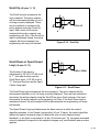
Lead Frequency (J6 pins 1, 3)
The Lead Frequency is a pulse train
input that the MLP–Trim uses to
determine the speed of the lead
motor. For signal level specifications,
refer to References: Appendix A,
MLP–Trim Specifications.
1
Signal
3
Common
J6
Figure 2-6 Lead Frequency
2-8
Feedback Frequency
(J6 pins 2, 3)
The Feedback Frequency is a pulse
train input that the MLP–Trim uses to
determine the speed of the follower
motor. For signal level specifications
refer to References: Appendix A,
MLP–Trim Specifications.
2
Signal
3
Common
J6
Figure 2-7 Feedback Frequency
DANGER
If the Feedback Frequency is lost,
the MLP-Trim will command a 100% Speed Out
and the motor will run at 100% capacity.
This can cause severe injury, death or
equipment damage.
Run (J6 pins 4, 8)
When the Run input (J6 pin 4) is
momentarily shorted to common, the
MLP–Trim enters Run. As a
momentary input, Run is internally
latched and does not need to be
maintained by an operator device.
NOTE: Close the R–Stop and F–Stop
inputs prior to entering Run.
If you are only using one of
the Stop inputs, wire short the
other Stop input to common
or the MLP–Trim will not enter
“Run”.
RUN
4
8
J6
Figure 2-8 Run
2-9
Jog (J6 pins 5, 8)
Jog is a maintained input. When Jog
is closed, the MLP–Trim sends a
Speed Command Out signal to the
drive at the selected jog speed. As a
maintained input, Jog is only active
when the operator device is closed.
NOTE: Close the R–Stop and
F–Stop inputs and open the
Run input, prior to entering
Jog. If you are only using
one of the Stop inputs, wire
short the other Stop input to
common or the MLP–Trim will
not enter Jog.
JOG
5
8
J6
Figure 2-9 Jog
R–Stop (J6 pins 6, 8)
R–Stop is a momentary input. When
it is opened, the MLP–Trim ramps to
a zero Speed Command Out at the
specified deceleration rate. As a
momentary input, R–Stop is internally
latched and does not need to be
maintained by an operator device.
6
8
R-STOP
J6
Figure 2-10 R–Stop
2 - 10
F-Stop (J6 pins 7, 8)
F-Stop is a momentary input. When
it is open, the MLP–Trim stops
immediately (zero RPM) and ignores
the specified deceleration rate. As a
momentary input, F-Stop is internally
latched and does not need to be
maintained by an operator device.
F-STOP
7
8
J6
Figure 2-11 F–Stop
Master / Follower
(J6 pins 9, 13)
This input determines the MLP–
Trim's mode of operation and
resulting scaling formula that the
control algorithm uses. The MLP–
Trim is in Master mode when the
circuit is open, and Follower or Offset
mode if the circuit is shorted to the
common.
9
MASTER
13
FOLLOWER
J6
Figure 2-12 Master / Follower
2 - 11
Setpoint Select (J6 pins 10, 13)
The Master and Follower setpoints
are determined by the Setpoint Select
input combined with the Master /
Follower Input. For access to Master
Control Parameters 1 and 2 and
Follower Control Parameters 3 and 4,
refer to the chart below.
10
13
CONTROL
PARAMETER 1 OR 3
CONTROL
PARAMETER 2 OR 4
J6
Figure 2-13 Setpoint Select
Setpoint Select / Open
2 - 12
Setpoint Select / Closed
Master / Follower
Input Open
Master Control Parameter 1
Master Control Parameter 2
Master / Follower
Input Closed
Follower Control Parameter 3
Follower Control Parameter 4
Scroll Up (J6 pins 11, 13)
The Scroll Up input increments the
active setpoint. The active setpoint
will be incremented whether or not it
is being currently displayed. There
are two methods to increment the
active setpoint using the Scroll Up
input. Each closure of the input
increments the active setpoint one
engineering unit. Also, if the Scroll Up
input is maintained closed, the active
setpoint will be incremented one
engineering unit every half second.
Scroll Down or Open/Closed
Loop (J6 pins 12, 13)
11
13
SCROLL UP
J6
Figure 2-14 Scroll Up
12
13
The function of this input is
determined by CP-60. If CP-60 is set
to "1", this input functions as the
Scroll Down input. If CP-60 is set to
"2", this input functions as the Open/
Closed Loop input.
SCROLL DOWN
J6
Figure 2-15 Scroll Down
The Scroll Down input decrements the active setpoint. The active setpoint will be
decremented whether or not it is being currently displayed. There are two methods to
decrement the active setpoint using the Scroll Down input. Each closure of the input
decrements the active setpoint one engineering unit. Also, If the Scroll Down input is
maintained closed, the active setpoint will be decremented one engineering unit every
half second.
The Open/Closed Loop input determines the basic manner in which the control
algorithm operates. In the Closed Loop position (J6 pin 12 open), the control algorithm
adjusts the speed command output to reduce the error to zero (setpoint minus
feedback). In the Open Loop position (J6 pin 12 shorted to pin 13), the speed command
output is adjusted in response to the setpoint changes only, and feedback and error are
ignored.
2 - 13
Analog Input (J6 pins 18, 19)
The Analog Input can be used for
frequency or setpoint replacement in
the Master and Follower modes of
operation, or the offset input in the
Offset mode of operation. Refer to
CP-84 for discussion on the
functional allocation of the analog
input.
18
Signal
19
Common
J6
Figure 2-16 Analog Input
2 - 14
OUTPUTS
Speed Command Out
(J3 pins 1, 2)
Speed Command Out is an isolated
analog output signal that is sent to
the motor drive to control the speed
of the motor. Wire the Speed
Command Out into the speed signal
input of the drive. If the motor drive
has a potentiometer speed control,
remove the potentiometer
connections and wire the Speed
Command Output to the
potentiometer wiper input. The
MLP–Trim's isolated common should
always be connected to the drive
common.
Speed Command Out
SIGNAL INPUT
* DRIVE COMMON
1
Isolated Common
2
J3
MOTOR DRIVE
*
Do not connect the Drive Isolated Common to other
logic commons
Figure 2-17 Speed Command Out
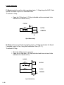
Digital Output 1 (J6 pin 15, 17)
The Digital Output 1 can be programmed to activate as a function of various alarm
conditions or as a function of the drive enable logic. Refer to CP-10 for functional
allocation of Digital Output 1.
NOTE: This is an open-collector relay driver. For specification details, see References:
Appendix A - MLP–Trim Specifications. Use an external DC power supply to
power the relays. Free-wheeling diodes are incorporated internally in the MLP–
Trim and do not need to be added externally.
2 - 15
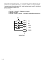
Digital Output 2 (J6 pin 16,17)
The Digital Output 2 can be programmed to activate as a function of various alarm
conditions or as a function of the drive enable logic. Refer to CP-11 for functional
allocation of Digital Output 2.
NOTE: This is an open-collector relay driver. Use an external DC power supply to
power the relays. Free-wheeling diodes are incorporated internally in the
MLP–Trim and do not need to be added externally.
+V_DO
+
14
DIG_OUT1
15
R1
DIG_OUT2
16
R2
Common
17
EXTERNAL
DC
POWER
SUPPLY
(50V Max)
–
J6
Figure 2-18 Digital Output 1 and Digital Output 2
Auxiliary DC Power (J1 pin 1, 2)
The 5 volt output (J1 pin 1) is a DC regulated output that can be used to power
encoders or other auxiliary equipment that is used in conjunction with the MLP–Trim. If
this output is used, it will nullify optical isolation.
WARNING
Do not exceed
the maximum current output of
150 mA for +5 VDC.
Exceeding the maximum
current output
can damage the MLP–Trim.
2 - 16
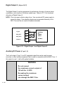
SERIAL COMMUNICATIONS
NOTE: The installation of this motor control must conform to area and local electrical
codes. See The National Electrical Code (NEC,) Article 430 published by the
National Fire Protection Association, or The Canadian Electrical Code (CEC).
Use local codes as applicable.
The Serial Communications interface on the MLP–Trim complies with EIA Standard
RS–485-A for balanced line transmissions. This interface allows the host computer to
perform remote computer parameter entry, status or performance monitoring, and
remote control of the MLP–Trim. See Operations: Serial Communications, for
information on using Serial Communications. The MLP-Trim is designed to use with an
isolated RS232 to RS485 converter.
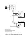
Figure 2-19 illustrates a multidrop installation of the Serial Communications link and
Figure 2-20 illustrates the Serial Communications connections.
Contrex
7
SET
POINT
4
TACH
Contrex
Contrex
CODE
SELECT
1
–
CLEAR
8
5
2
0
9
CODE
SELECT
7
SET
POINT
4
6
3
TACH
.
1
–
ENTER
CLEAR
8
5
2
9
CODE
SELECT
SET
POINT
3
TACH
0
7
6
4
1
.
–
ENTER
CLEAR
8
5
2
0
9
6
3
.
ENTER
Isolated
RS232 to RS485
Converter
Contrex
CODE
SELECT
SET
POINT
TACH
Contrex
Contrex
7
4
1
–
CLEAR
8
9
CODE
SELECT
5
6
SET
POINT
2
0
7
4
3
.
TACH
1
–
ENTER
CLEAR
9
8
CODE
SELECT
7
6
5
SET
POINT
3
2
TACH
4
1
.
0
–
ENTER
CLEAR
8
5
2
0
9
6
3
.
ENTER
Figure 2-19 MLP–Trim Multidrop Installation
2 - 17
Isolated
RS232 to RS485
Converter
TXD/
COM RXD
—
TXD/
RXD
+
J2
1
T/R+
2
T/R–
3
COM
J2
2
MLP–Trim #1
MLP–Trim #2
1
T/R+
2
T/R–
3
COM
1
1. Shield only at one end of the cable.
2. If you need to terminate the communication line, then terminate
it at the unit which is the furthest away from the converter. A 100
ohm, 1/2 Watt resistor will usually terminate successfully. Refer
to EIA Standard RS485A, for more information.
Figure 2-20 MLP–Trim Serial Communications Connections
2 - 18
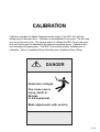
CALIBRATION
Calibration matches the Speed Command analog output of the MLP–Trim with the
analog input of the motor drive. Calibration is accomplished in two steps. The first step
is to set up the motor drive. The second step is to calibrate the MLP–Trim to the motor
drive so that the speed is adjusted to the maximum operating speed. Calibration also
zero and spans the analog input. The MLP–Trim must be properly installed prior to
calibration. Refer to Installation/Setup; Mounting, and Installation/Setup; Wiring.
DANGER
Hazardous voltages.
Can cause severe
injury, death or
damage
to the equipment.
Make adjustments with caution.
2 - 19
MOTOR DRIVE SET UP
1) Put the MLP–Trim in “R–Stop” by opening the R–Stop input (J6 pins 6, 8).
Refer to Installation/Setup: Wiring, Inputs, R–Stop.
2) Set the drive's acceleration and deceleration potentiometers to their fastest
rates (minimum ramp time). The goal is to make the drive as responsive as
possible, which allows the MLP–Trim to control the speed changes.
3) If the drive has a maximum speed (span) potentiometer, set it to the highest
setting at which the motor drive is capable of running. The maximum speed
at which you want the system to operate will be controlled by the MLP–Trim.
4) If the drive has a zero speed potentiometer, adjust it to eliminate any motor
creep.
5) If the drive has an IR compensation potentiometer, set it at minimum.
6) Each motor drive has settings that are unique to its particular model. Adjust
any remaining drive settings according to the manufacturer's
recommendations.
2 - 20
MLP–TRIM CALIBRATION
1) Make sure that the MLP–Trim is still in “R–Stop”. If the MLP–Trim is not in
“R-Stop”, then put it in “R–Stop” by opening the R–Stop logic input
(J6 pins 6, 8). Refer to Installation/Setup: Wiring, Inputs, R–Stop.
2) Enter the resolution (PPRs) of the feedback sensor in the PPR Feedback
Control Parameter (CP-31) by entering the following on the keypad:
Press “Code Select”
Enter “31” (PPR Feedback)
Press “Enter”
Enter the Pulses Per Revolution (PPR) of the feedback sensor
Press “Enter”
The Tach for the Direct mode is now scaled.
3) Set the MLP–Trim's maximum speed potentiometer (located on the rear) as
far counter clockwise as it will turn. This is the minimum speed setting.
4) Enable the MLP–Trim's Direct mode by entering the following on the keypad:
Press “Code Select”
Enter “61” (Direct Enable)
Press “Enter”
Enter “1”
Press “Enter”
5) Put the MLP–Trim into “Run” by deactivating (shorting) the R–Stop input
(J6 pins 6, 8) and the F–Stop input (J6 pins 7, 8) and then activating (shorting)
the Run input (J6 pins 4, 8). Although the motor is now in “Run”, it will have
zero speed until you adjust the Direct Setpoint (in the next step).
6) Gradually set the MLP–Trim's Direct Setpoint to 90% by entering the following
on the keypad:
Press “Code Select”
Enter “6” (Direct Setpoint)
Press “Enter”
Enter “10”
Press “Enter”
Enter “20”
Press “Enter”
2 - 21
Continue to gradually increase these increments by ten until you reach “90”.
Since there are no acceleration/deceleration ramps in Direct mode, a
sudden increase to “90” could cause damage in some systems.
7) Turn the MLP–Trim's maximum speed potentiometer clockwise until the
drive motor's RPMs are at the maximum operating speed at which you want
the system to operate. The maximum operating speed is the same speed
that you will enter in Max RPM Feedback (CP-34) to scale for the Master
mode of operation (Refer to Operation: Control Parameters. Master Mode.
Check the speed (RPMs) by pressing the “Tach” key. If the lowest setting on
the MLP–Trim's maximum speed potentiometer still exceeds the maximum
speed at which you want the system to operate, then adjust the maximum
speed (span) potentiometer on the motor drive until the desired speed is
reached.
8) Put the Direct Setpoint back to 0% by entering the following on the keypad:
Press “Code Select”
Enter “6” (Direct Setpoint)
Press “Enter”
Enter “0”
Press “Enter”
9) Disable the MLP–Trim's Direct mode by entering the following on the
keypad:
Press “Code Select”
Enter “61” (Direct Enable)
Press “Enter”
Enter “0”
Press “Enter”
10) Put the MLP–Trim in “R–Stop” by opening the R–Stop input (J6 pins 6, 8).
2 - 22
ANALOG INPUT CALIBRATION
The analog input is factory calibrated for zero and span levels at 0 - 10 VDC. If it is
necessary to field calibrate the analog input, follow these procedures.
Zero Adjust
1) Enter CP-85 (Analog Input Zero) by entering the following on the keypad:
Press "Code Select"
Enter "85"
Press "Enter"
2) Place zero volts (short) on the analog input (J6 pins 18, 19).
3) Press the "." (decimal point) key. The display should now read between 0.0
and 1.0. This step zero adjusts the analog input.
Span Adjust
1) Enter CP-86 (Analog Input Span) by entering the following on the keypad:
Press "Code Select"
Enter "86"
Press "Enter"
2) Place 10.0 VDC on the analog input (J6 pins 18, 19).
3) Press the "." (decimal point) key. The display should now display a value from
90.0 to 100.0 for a 10 VDC input. This step span adjusts the analog input.
2 - 23
–NOTES—
2 - 24
Operation
Keypad Operation
Keypad Lockout
Control Parameters (CP)
Direct Mode
Master Mode
Follower Mode
Offset Mode
Inverse Master Mode
Inverse Follower Mode
Acceleration/Deceleration
Tuning
Alarms
Limits
Jog
Logic Control
Logic Inputs
Logic Outputs
Monitor Parameters (MP)
Input Monitoring
Output Monitoring
Performance Monitoring
Status Monitoring
Serial Communications
Using Serial Communications
Communications Software Design
3-1
3-2
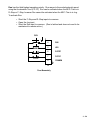
KEYPAD OPERATION
The front panel of the MLP–Trim is an easy to use keypad that gives you direct access
to the Parameters (Control Parameters and Monitor Parameters) by entering the
Parameter Code. You can also use the keypad to change the value of a Control
Parameter. The keypad has keys for Code Select, Enter, Clear, and Scroll Up/Down.
It also has numeric keys and two dedicated keys: Setpoint and Tach. The LED display
is the above the keys. Figure 3-1 displays the location of the keys and LED display on
the keypad. Table 3-1 demonstrates basic keypad entry.
The keypad functions as follows:
Code Select Key
Press this key prior to entering a Parameter Code (either a
Control Parameter or a Monitor Parameter).
Numeric Keys
Use the numeric keys to enter a Parameter Code for either a
Control Parameter (CP) or a Monitor Parameter (MP) or to
enter a value for a Control Parameter. Use the Enter key after
each entry. Use the Clear key to delete your entry.
Dedicated Keys
The Setpoint key and the Tach key are shortcut keys. The
Setpoint key accesses the active setpoint variable directly and
the Tach key accesses the tach variable directly (rather than
manually entering the Code Parameter).
Scroll Up/Down Keys
These keys will change the active setpoint value, even if that
setpoint is not displayed in the LED Display. Each time you
press the scroll up key, the active setpoint will increase by one
increment. Each time you press the scroll down key, the active
setpoint value will decrease by one increment. It will also
automatically scroll through the increments or decrements if
you hold the key down.
LED Display
The two digit Parameter Code is displayed on the left LED
Display. The Parameter Code's value is displayed on the right
LED display. This value can be up to four digits.
3-3
Table 3-1 Basic Keypad Entry
To Enter a Parameter Code:
Press “Code Select”.
Enter a Parameter Code (For a Control Parameter or Monitor Parameter).
Press “Enter” (within 15 seconds).
The Parameter Code and it's current value are displayed on the LED display.
The Parameter Code decimal point is illuminated.
To Enter a Parameter Value:
Follow the steps to enter a Parameter Code.
Enter a new value (Use the numeric keys) .
Press “Enter” (within 15 seconds).
The Parameter Code decimal point turns “Off”.
(For Control Parameters only - Monitor
Parameters can not be changed
manually)
To Use the Tach Key:
Press “Tach’.
The scaled Engineering Unit Feedback is displayed.
To Use the Setpoint Key:
Press “Setpoint”.
The active setpoint and its value are displayed.
To Use the Up/Down
Scroll Keys:
Press the “Up” scroll key to increase the active setpoint value.
Press the “Down” scroll key to decrease the active setpoint value.
Parameter Code
Parameter Value
(2 digits)
(up to 4 digits)
Led
Display
Code Select
Key
Dedicated
Keys
Numeric
Keys
Enter
Key
Up/Down
Scroll Keys
Clear
Key
Figure 3-1 The MLP–Trim Front Panel
3-4
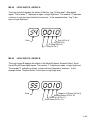
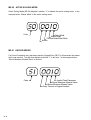
KEYPAD LOCKOUT
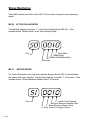
Keypad Lockout (CP-98) displays the present status of the keypad lockout. When the
keypad is locked, then “LOC” is displayed:
Code
Locked
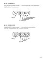
When the Keypad is unlocked, then “ULOC” is displayed:
Code
Unlocked
To lock out the keypad, enter a numerical “password” between “1” and “9999” in
Keypad Lockout (CP-98), then press the “enter” key. This numerical password will flash
briefly on the screen, then the screen will display “LOC”. To unlock the keypad, enter
the same numerical password in Keypad Lockout (CP-98). The number will flash briefly
on the screen and then the screen will display “ULOC”. Control Parameters and
Monitor Parameters may be monitored during lockout, however, Control Parameters
can not be changed during lockout. The Clear/7 procedure will default Keypad Lockout
(CP-98) to “ULOC” (unlocked).
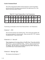
CP-79, Setpoint Lockout Mask, determines which setpoints are disabled when the
keypad is locked out. If CP-79 is set to "0", then none of the setpoints (CP-01 through
CP-04) are disabled. If CP-79 is set to "1", then all four of the setpoints are disabled. If
CP-79 is set to "2", then CP-02 and CP-04 are disabled while CP-01 and CP-03 remain
enabled.
3-5
CAUTION:
Make certain that you record your password in the space provided on page 3-6, as your
password becomes transparent once you have entered it. If you forget your password,
you can use the Clear/7 procedure to revert back to the default “ULOC” (unlocked).
Please note, however, that the Clear/7 procedure will revert all of the Control
Parameters back to their original default values and you will lose any changes that you
have made to the Control Parameters. Therefore, make certain that you have recorded
all Control Parameter changes in the space provided in Appendix D before you use the
Clear/7 procedure. Refer to Troubleshooting: Troubleshooting, for instructions on the
Clear/7 procedure. If you are uncertain how to enter a Control Parameter, review the
Operations: Keypad section.
Record your numeric Keypad Lockout password here:
3-6
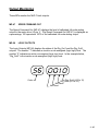
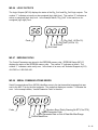
CONTROL PARAMETERS
Parameters are divided into two classifications; Control Parameters (CP) and Monitor
Parameters (MP). The numbered code that represents the Parameter is the Parameter
Code. The operational data is the Parameter's value.
Control Parameter 05
=
50 (default)
Monitor Parameter 40
=
200 (arbitrary)
Parameters =
Parameter Code
Parameter Value
This section is about Control Parameters. Monitor Parameters are explained in
Operation: Monitor Parameters.
The MLP–Trim comes factory pre-loaded with a complete set of default Control
Parameters values. The majority of these default settings are suitable for most
applications and do not require modification.
Control Parameters allow you to enter data that is unique to your system (e.g., encoder
resolution, Lead to Follower ratios) and modify the MLP–Trim for your specific needs
(e.g., maximum RPMs, setpoints, acceleration/deceleration ramp rates) by entering a
parameter value.
The MLP–Trim is designed to execute either the Direct mode of operation, the Master
(stand-alone) mode of operation or the Follower mode of operation. The values that
you enter in the relevant Control Parameters, as well as the manner in which you wire
and calibrate your MLP–Trim, determine which of the modes of operation your MLP–
Trim is set up for. The mode of operation that you use is determined by your systems
operational requirements.
The following subsections demonstrate how to enter Control Parameters for the Direct
mode, Master (stand-alone) mode or the Follower mode of operation. In addition,
Control Parameters for speed change, stability, warning methods and fast forward are
addressed in the subsections on Acceleration/Deceleration, Tuning, Alarms, and Jog.
3-7
Direct Mode
In the Direct mode of operation, the Speed Command output from the MLP–Trim that is
connected to the motor drive can be set directly. Direct mode is an open-loop mode of
operation. Scaling, Acceleration/Deceleration, and closed loop compensation (PID)
software are not involved in the Direct mode. The Direct mode is used in conjunction
with the Run and Stop controls.
Caution: To avoid damage to your system, the MLP–Trim must be calibrated and the
motor drive set up before you enter the Direct Control Parameters. Refer to
Installation/Setup: Calibration.
The Direct Setpoint (CP-06) is entered as a percentage of the MLP–Trim's calibrated
full scale Speed Command output. To enable or disable Direct mode, use the Direct
Enable (CP-61).
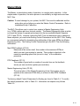
The factory default Control Parameters for the Direct mode are found in Table 3-2. To
modify the default parameters, refer to Table 3-3.
Table 3-2 Default Direct Mode Control Parameters
CP
Parameter Name
Parameter Value
CP-06
Direct Setpoint
0
CP-61
Direct Enable
0
Table 3-3 Entering Direct Mode Control Parameters
3-8
CP
Parameter Name
Parameter Value
CP-06
Direct Setpoint
Enter the percentage of the calibrated
full scale Speed Command output at
which you want your system to operate.
CP-61
Direct Enable
Enter “1” to enable the Direct Mode.
Enter “0” to disable the Direct Mode.
Master Mode
The Master, or stand-alone mode of operation, is a single motor operation. In this
simple mode of operation, the entire process is controlled by a single motor and one
MLP–Trim.
Caution: To avoid damage to your system, the MLP–Trim must be calibrated and the
motor drive set up before you enter the Master Control Parameters. Refer to
Installation/Setup: Calibration.
The MLP–Trim allows you to control your system in Master Engineering Units
(e.g., RPMs, gallons per hour, feet per minute). The Master Engineering Units at which
you want the system to operate are entered into the two available Master Setpoints
(CP-01 and CP-02). However, before the MLP–Trim can determine how to operate at
those setpoints, you must enter Scaling Control Parameters into the MLP–Trim. Scaling
is a convenient method for translating the relationship of the motor RPMs into Master
Engineering Units. The Scaling Control Parameters give the MLP–Trim the following
information:
Max RPM Feedback (CP-34)
Measured at the sensor shaft, this number is the maximum RPMs at
which you want your system to operate. This number is identical to the
maximum operating speed that you set in step 7 of the calibration
procedure.
PPR Feedback (CP-31)
The number of gear teeth or number of encoder lines on the feedback
sensor per one revolution (pulses per revolution).
Master Engineering Units (CP-20)
The actual value of the Master Engineering Units if the system were to
operate at the maximum RPMs that you entered in Max RPM Feedback
(CP-34).
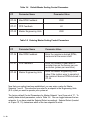
The factory default Control Parameters for Scaling are found in Table 3-4. To modify
the default parameters, refer to Table 3-5. Information on setpoint entry follows
Table 3-5.
3-9
Table 3-4
Default Master Scaling Control Parameters
CP
Parameter Name
CP-34
Max RPM Feedback
CP-31
PPR Feedback
CP-20
Master Engineering Units
Parameter Value
2000
60
2000
Table 3-5 Entering Master Scaling Control Parameters
CP
Parameter Name
Parameter Value
CP-34
Max RPM Feedback
Enter the maximum desired RPMs,
measured at the sensor shaft.
CP-31
PPR Feedback
Enter the number of gear teeth or
encoder lines on the sensor per one
revolution (pulses per revolution).
CP-20
Master Engineering Units
Enter the Master Engineering Units
value if the system were to operate at
the maximum desired RPMs entered in
CP-34.
Now that your scaling has been established, you can enter a value for Master
Setpoints 1 and 2. The value that you enter for a setpoint is the Engineering Units
(E.U.s) that you want to operate your system at.
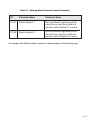
The factory default Control Parameters for Master Setpoint 1 and 2 are set at “0”. To
modify these default parameters, refer to Table 3-6. You can toggle between the two
setpoints, if you have wired the Setpoint Select accordingly. Setpoint Select (located
at J6 pins 10, 13), determines which of the two setpoints is active.
3 - 10
Table 3-6 Entering Master Setpoint Control Parameters
CP
Parameter Name
Parameter Value
CP-01
Master Setpoint 1
Enter the Master Engineering Units
value that you want your system to
operate at when Setpoint 1 is active.
CP-02
Master Setpoint 2
Enter the Master Engineering Units
value that you want your system to
operate at when Setpoint 2 is active.
An example of the Master mode of operation is demonstrated on the following page.
3 - 11
Master Mode Example
The following example demonstrates how scaling and setpoint Control Parameters are
entered for a typical Master mode of operation:
A pump delivers 15 gallons/minute when the motor runs at a maximum
RPM of 1725. The motor shaft is equipped with a 30 tooth Ring kit.
The Master Engineering Units are gallons per minute. Master Setpoint
1 will be setup to pump 10 gallons per minute when it is the active
setpoint. Master Setpoint 2 will be setup to pump 5 gallons per minute
when it is the active setpoint.
Table 3-7 shows the scaling Control Parameters that would be entered in the MLP–Trim
for this example.
Table 3-7 Master Mode Control Parameters Example
CP
Parameter Name
Parameter Value
CP-34
Max RPM Feedback
CP-31
PPR Feedback
CP-20
Master Engineering Units
15.0
CP-01
Master Setpoint 1
10.0
CP-02
Master Setpoint 2
5.0
1725
30
After the Scaling and the Master Setpoints for your system have been entered, you can
enter the Acceleration/Deceleration Control Parameters for the Master mode. The
Acceleration/Deceleration Control Parameters are identical for both the Master and the
Follower modes of operations. Acceleration/Deceleration is discussed in Operation:
Control Parameters, Acceleration/Deceleration.
3 - 12
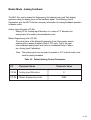
Master Mode - Analog Feedback
The MLP-Trim can be scaled for Engineering Unit setpoint entry and Tach display
operation using the analog input for the feedback signal. The following Control
Parameters give the MLP-Trim the necessary information for analog feedback operation
in Master mode.
Analog Input Allocation (CP-84)
Setting CP-84, Analog Input Allocation, to a value of "2" allocates the
analog input to be used as the feedback source.
Master Engineering Units (CP-20)
The actual value of the Master Engineering Units if the system were to
operate with an analog feedback level of 10.0 volts. This is the maximum calibrated analog input level (refer to Installation/Setup: Calibration, Analog Input Calibration).
Note: The analog input does not need to operate to 10.0 volts full scale to be
used for analog feedback.
Table 3-8 Default Scaling Control Parameters
CP
Parameter Name
CP-84
Analog Input Allocation
CP-20
Master Engineering Units
Parameter Value
0
2000
3 - 13
Table 3-9 Entering Master Scaling Analog Feedback Parameters
CP
Parameter Name
Parameter Value
CP-84
Analog Input Allocation
Enter a value of "2" to allocate the
analog input as the feedback source.
CP-20
Master Engineering Units
Enter the Master Engineering Unit
value for an analog feedback level of
10.0 volts.
Note:
3 - 14
The Max RPM Feedback (CP-34) and PPR Feedback (CP-31) control
parameters, used for scaling Master mode with frequency feedback, are
ignored when using analog feedback scaling.
Master Mode Analog Feedback Example
The following example demonstrates Master mode scaling using analog feedback:
A pump delivers 20.0 gallons per minute when the pump motor rotates at 1800
RPM. A tachometer connected to the pump motor produces a 10.0 volt signal
when the motor rotates at 1800 RPM. Master Setpoint 1 will be setup for an
operation of 12.0 gallons per minute. Master Setpoint 2 will be setup for an
operation of 17.5 gallons per minute.
Table 3-10 shows the scaling Control Parameter that would be entered for the above
system operation.
Table 3-10
Master Mode Feedback Allocation Example
CP
Parameter Name
CP-84
Analog Input
Allocation
CP-20
Value
Remarks
2
Allocates The analog input as the
feedback source.
Master Engineering
Units
20.0
This is the Engineering Unit value
that would be present if the analog
input were at 10.0 volts.
CP-01
Master Setpoint 1
12.0
The desired Master Setpoint 1.
CP-02
Master Setpoint 2
17.5
The desired Master Setpoint 2.
3 - 15
Master Mode - Analog Setpoint
The MLP-Trim can be scaled for Engineering Unit setpoint entry and Tach display
operation using the analog input for the setpoint. The following Control Parameters give
the MLP-Trim the necessary information for analog setpoint operation in Master mode.
Analog Input Allocation(CP-84)
Setting CP-84, Analog Input Allocation, to a value of "4" or "5" allocates
the analog input to be used as Master Setpoint 1 or Master Setpoint 2,
respectively.
Master Engineering Units (CP-20)
The actual value of the Master Engineering Units if the system were to
operate with an analog setpoint level of 10.0 volts. This is the maximum
calibrated analog input level (refer to Installation/Setup: Calibration,
Analog Input Calibration).
Note: The analog input does not need to operate to 10.0 volts full scale to be
used for setpoint replacement.
Max RPM Feedback (CP-34)
This is the maximum RPM of the feedback sensor shaft during system
operation. This number should be the same as the maximum operating
speed set during step 7 of the calibration procedure.
PPR Feedback (CP-31)
The number of gear teeth or encoder lines on the follower feedback
sensor per revolution.
Table 3-11
3 - 16
Default Scaling Control Parameters
CP
Parameter Name
Parameter Value
CP-84
Analog Input Allocation
0
CP-20
Master Engineering Units
0
CP-34
Max RPM Feedback
CP-31
PPR Feedback
2000
60
Table 3-12
Entering Master Scaling Analog Setpoint Parameters
CP
Parameter Name
Parameter Value
CP-84
Analog Input Allocation
Setting CP-84 to a value of "4" or "5"
allocates the analog input to be used
as Master Setpoint 1 or Master
Setpoint 2, respectively.
CP-20
Master Engineering Units
Enter the Master Engineering Unit
value for an analog setpoint level of
10.0 volts and feedback RPM of CP-34.
CP-34
Max RPM Feedback
Enter the maximum operating RPMs
measured at the feedback sensor shaft.
CP-31
PPR Feedback
Enter the resolution of the feedback
sensor.
3 - 17
Master Mode Analog Setpoint Example
The following example demonstrates Master mode scaling using analog setpoint:
A pump delivers 20.0 gallons per minute when the pump motor rotates
at 1800 RPM. The pump motor is equipped with a 60 tooth ring kit
feedback sensor. The pump will run at 20.0 gallons per minute with an
analog input of 10 volts.
Table 3-13
3 - 18
Master Mode Setpoint Allocation Example
CP
Parameter Name
Value
CP-84
Analog Input
Allocation
CP-20
Master Engineering
Units
20.0
This is the Engineering Unit value
that would be present if the analog
input were at 10.0 volts.
CP-34
Max RPM Feedback
1800
The maximum operating RPM of
the feedback shaft.
CP-31
PPR Feedback
4
60
Remarks
Allocates the analog input as
Master Setpoint 1.
Feedback sensor resolution.
Follower Mode
The Follower mode of operation is the most frequently used mode of operation. It is a
multi-motor operation in which the entire process can be controlled by any number of
motors and MLP–Trims.
The MLP–Trim allows you to control your system in Follower Engineering Units
(e.g., Follower to Lead ratio or percentage of RPMs, gallons per minute, feet per
minute). The Follower Engineering Units that you want the system to operate at are
entered into the two available Follower Setpoints (CP-03 and CP-04). However, before
the MLP–Trim can determine how to operate at these setpoints, you must enter Scaling
Control Parameters into the MLP–Trim. Scaling is a convenient method for translating
the relationship of the Lead and Follower motor RPMs into Follower Engineering Units.
Scaling Control Parameters give the MLP–Trim the following information:
Max RPM Lead (CP-33)
Measured at the Lead sensor shaft, this number is the maximum RPMs
at which the Lead will operate in your system.
Max RPM Feedback (CP-34)
Measured at the sensor shaft, this number is the maximum RPMs at
which you want the follower to operate when the Lead is operating at its
maximum RPMs. This number is identical to the maximum operating
speed that you set in step 7 of the calibration procedure.
PPR Lead (CP-30)
The number of gear teeth or number of encoder lines on the Lead
sensor per revolution (pulses per revolution).
PPR Feedback (CP-31)
The number of gear teeth or number of encoder lines on the Follower
feedback sensor per revolution.
Follower Engineering Units (CP-21)
Enter a number that will represent the setpoint Engineering Units when
the Lead and Follower are operating at their maximum RPMs. This
number is usually either the ratio of Max RPM Feedback (CP-34) to
Max RPM Lead (CP-33) or the ratio of Follower to Lead Engineering
Units at maximum desired RPM. When this number is also entered as
a setpoint (CP-03 or CP-04), the Follower will operate at maximum
desired RPM when the Lead is at maximum desired RPM.
3 - 19
The factory default Control Parameters for Scaling are found on Table 3-14. To modify
these default parameters, refer to Table 3-15. If you are uncertain how to enter a
Control Parameter, review the Operations: Keypad section.
Table 3-14
Default Follower Scaling Control Parameters
CP
Parameter Name
Parameter Value
CP-33
Max RPM Lead
2000
CP-34
Max RPM Feedback
2000
CP-30
PPR Lead
60
CP-31
PPR Feedback
60
CP-21
Follower Engineering Units
1.000
Table 3-15 Entering Follower Scaling Control Parameters
3 - 20
CP
Parameter Name
Parameter Value
CP-33
Max RPM Lead
Enter the maximum operating RPM of
the Lead motor, measured at the Lead
sensor shaft (pulses per revolution).
CP-34
Max RPM Feedback
Enter the maximum desired RPM of the
Follower motor, measured at the
Follower feedback sensor shaft.
CP-33
PPR Lead
Enter the number of gear teeth or
encoder lines on the Lead sensor.
CP-31
PPR Feedback
Enter the number of gear teeth or
encoder lines on the Follower
feedback sensor.
CP-21
Follower Engineering Units
Enter the Engineering Units value if the
Lead (CP-33) is operating at maximum
RPM and the Follower (CP-34) is
operating at maximum RPM.
With your scaling established, you can enter values for Follower Setpoints 1 and 2
(CP-03, CP-04). The value that you enter for a setpoint is the ratio of the Follower
E.U.s at which you want to operate the system, divided by the E.U.s that the Lead is
operating at.
Follower E.U. desired
Setpoint =
________________________________
Lead E.U. operation
You can toggle between the two setpoints, if you have wired the Setpoint Select
accordingly. Setpoint Select (located at J6 pins 10, 13) determines which of the two
setpoints is active . The factory preset, default Follower Setpoints 1 and 2 (CP-03 and
CP-04) are set at “0”. To modify these default parameters, refer to Table 3-16.
Table 3-16 Entering Follower Setpoint Control Parameters
CP
Parameter Name
Parameter Value
CP-03
Follower Setpoint 1
Divide the Follower E.U. that you want,
by the Lead E.U. that the Lead is
operating at, and enter that value.
CP-04
Follower Setpoint 2
Divide the Follower E.U. that you want,
by the Lead E.U. that the Lead is
operating at, and enter that value.
Examples of the Follower mode of operation are demonstrated on the following pages.
3 - 21
Follower Mode Examples A and B
Example A demonstrates how scaling and setpoint Control Parameters are entered for
a typical Follower mode of operation that uses a ratio setpoint:
The Lead pump delivers 10 gallons/minute when the motor is running at
a maximum RPM of 1725. The Lead sensor shaft is equipped with a 60
tooth Ring kit. The Follower pump delivers 30 gallons/minute when the
motor is running at a maximum RPM of 1800. The Follower sensor
shaft is equipped with a 30 tooth Ring kit. Follower Setpoint 1 will be
set so that when the Lead pump delivers 5 gallons/minute, the Follower
pump will deliver 15 gallons/minute. Follower Setpoint 2 will be set so
that when the Lead pump delivers 5 gallons/minute, the Follower pump
will deliver 22.5 gallons/minute.
Table 3-17 shows the Control Parameters that would be entered in the MLP–Trim for
Example A.
To find the ratio for the Follower Engineering Units (CP-21) for Example A:
Follower E.U. at Max Follower RPM
Follower E.U. (CP-21)
=
_____________________________________________________
30
=
Lead E.U. at Max Lead RPM
30 gal / min
___
=
The Follower Engineering Units when the Follower is operating
at the maximum RPM.
Divided by
10 gal / min
The Lead Engineering Units when the Lead is
operating at maximum RPM.
Equals
3.00
3 - 22
3
10
Follower Engineering Units (CP-21) as a ratio of Follower to
Lead.
To find Follower Setpoint 1 (CP-03) for Example A:
Follower E.U. desired
Setpoint 1
________________________________
=
15
=
Lead E.U. operation
15 gal/min
___
=
3
5
The Follower Engineering Units (gallon per minute) at which
you want the Follower to operate - do not confuse this with the
full capacity gal/min that the Follower is capable of pumping.
Divided by
5 gal/min
The Lead Engineering Units that the Lead is operating at - do
not confuse this with the full capacity that the Lead is capable
of operating at.
Equals
3.00
Follower Setpoint 1 (CP-03) value.
To find Follower Setpoint 2 (CP-04) for Example A:
Follower E.U. desired
Setpoint 2
________________________________
=
Lead E.U. operation
22.5
=
___
=
4.50
5
22.5 gal/min
The Follower Engineering Units (gallon per minute) at which
you want the Follower to operate - do not confuse this with the
full capacity gal/min that the Follower is capable of pumping.
Divided by
5 gal/min
The Lead Engineering Units (gallon per minute) that the Lead is
operating at - do not confuse this with the full capacity that the
Lead is capable of pumping.
Equals
4.50
Follower Setpoint 2 (CP-04) value.
3 - 23
Table 3-17 Follower Mode Control Parameters Example A
CP
Parameter Name
Parameter Value
CP-33
Max RPM Lead
1725
CP-34
Max RPM Feedback
1800
CP-30
PPR Lead
60
CP-31
PPR Feedback
30
CP-21
Follower E.U.
3.00
CP-03
Follower Setpoint 1
3.00
CP-04
Follower Setpoint 2
4.50
The MLP–Trim will adjust and monitor the speed of the Follower motor to achieve the
desired gallons/minute. This completes the scaling and setpoint information for
Example A. Example B is discussed in the following section.
3 - 24
Example B demonstrates how scaling and setpoint Control Parameters are entered for
a typical Follower mode of operation that uses a setpoint based on a percentage
setpoint:
The Lead pump delivers 20 gallons/minute of ingredient A. The Lead
motor's is running at a maximum RPM of 1800 and the Lead sensor
shaft is equipped with a 60 tooth Ring kit. The Follower pump delivers
10 gallons/minute of ingredient B. The Follower motor is running at a
maximum RPM of 1800 and the Follower sensor shaft is equipped with
a 60 tooth Ring kit. Follower Setpoint 1 will be set so that when the
Lead pump delivers 20 gallons/minute of ingredient A, the Follower will
deliver 10 gallons/minute of ingredient B. Setpoint 2 will be set so when
the Lead pump delivers 10 gallons/minute of ingredient A, the Follower
pump will delivers 7 gallons/minute of ingredient B.
Table 3-18 shows the Control Parameters that would be entered in the MLP–Trim for
Example B.
To find the ratio for the Follower Engineering Units (CP-21) for Example B:
Follower E.U. at Max Follower RPM
Follower E.U. (CP-21)
__________________________________________________
=
Lead E.U. at Max Lead RPM
10 gal/min
10
=
___
X
100(%) = 50
20
The Follower Engineering Units when the Follower is operating
at maximum RPM
Divided by
20 gal/min
The Lead Engineering Units when the Lead is operating at
maximum RPM
Multiplied by 100 (%) equals
50
Follower Engineering Units (CP-21) as a percent of Follower to
Lead.
3 - 25
To find Follower Setpoint 1 (CP-03) for Example B:
Follower E.U. desired
Setpoint 1
________________________________
=
x
100 (%)
Lead E.U. operation
10 gal/min
The Follower Engineering Units (gallons/minute of ingredient B)
at which you want the Follower to operate - do not confuse this
with the full capacity that the Follower is capable of pumping.
Divided by
20 gal/min
The Lead Engineering Units (gallons/minute of ingredient A)
that the Lead is operating at - do not confuse this with the full
capacity that the Lead is capable of operating at.
Multiplied by 100 (%) Equals
50
Follower Setpoint 1 (CP-03) value.
To find Follower Setpoint 2 (CP-04) for Example B:
Follower E.U. desired
Setpoint 2
________________________________
=
x
100 (%)
Lead E.U. operation
7 gal/min
The Follower Engineering Units (gallons/minute of ingredient B)
at which you want the Follower to operate - do not confuse this
with the full capacity that the Follower is capable of pumping.
Divided by
10 gal/min
The Lead Engineering Units (gallons/minute of ingredient A)
that the Lead is operating at - do not confuse this with the full
capacity that the Lead is capable of operating at.
Multiplied by 100(%) Equals
70
3 - 26
Follower Setpoint 2 (CP-04) value.
Table 3-18 Follower Mode Control Parameters Example B
CP
Parameter Name
Parameter Value
CP-33
Max RPM Lead
1800
CP-34
Max RPM Feedback
1800
CP-30
PPR Lead
60
CP-31
PPR Feedback
30
CP-21
Follower E.U.
50.0
CP-03
Follower Setpoint 1
50.0
CP-04
Follower Setpoint 2
70.0
The MLP–Trim will adjust and monitor the speed of the motors to achieve the desired
gallons/minute. That completes the scaling and setpoint information for Example B.
3 - 27
Follower Mode - Analog Lead
The MLP-Trim can be scaled for Engineering Unit setpoint entry and Tach display
operation using the analog input for the lead signal. The following Control Parameters
give the MLP-Trim the necessary information for analog lead operation in Follower
mode.
Analog Input Allocation(CP-84)
Setting CP-84, Analog Input Allocation, to a value of "1" allocates the
analog input to be used as the lead source.
Follower Engineering Units (CP-21)
The actual value of the Follower Engineering Units if the system were to
operate with an analog lead level of 10.0 volts and a feedback of Max
RPM Feedback (CP-34). This is the maximum calibrated analog input
level (refer to Installation/Setup: Calibration, Analog Input Calibration).
Note: The analog input does not need to operate to 10.0 volts full scale to be
used for analog lead.
Max RPM Feedback (CP-34)
This is the maximum RPM of the feedback sensor shaft during system
operation. This number should be the same as the maximum operating
speed set during step 7 of the calibration procedure.
PPR Feedback (CP-31)
The number of gear teeth or encoder lines on the follower feedback
sensor per revolution.
Table 3-19
3 - 28
Default Scaling Control Parameters
CP
Parameter Name
Parameter Value
CP-84
Analog Input Allocation
CP-21
Follower Engineering Units
1.000
CP-34
Max RPM Feedback
2000
CP-31
PPR Feedback
0
60
Table 3-20
Entering Follower Scaling Analog Lead Parameters
CP
Parameter Name
Parameter Value
CP-84
Analog Input Allocation
Setting CP-84 to a value of "1"
allocates the analog input to be used
as the lead signal.
CP-21
Follower Engineering Units
Enter the Follower Engineering Unit
value for an analog lead level of
10.0 volts and feedback of Max RPM
Feedback (CP-34). This is typically a
value of 1.000.
CP-34
Max RPM Feedback
Enter the maximum operating RPMs
measured at the feedback sensor shaft.
CP-31
PPR Feedback
Enter the resolution of the follower
feedback sensor.
Note:
The Max RPM Lead (CP-33) and PPR Lead (CP-30) control parameters, used
for scaling Follower mode with a frequency lead, are ignored when using
analog lead scaling.
3 - 29
Follower Mode Analog Lead Example
The following example demonstrates Follower mode scaling using analog lead:
A pump delivers 20.0 gallons per minute of ingredient A when the pump
motor rotates at 1800 RPM. A second pump delivers 40.0 gallons per
minute of ingredient B when the pump motor rotates at 1800 RPM. A
potentiometer connected to the analog input of the MLP-Trim produces
a 10.0 volt signal when the pump A (lead) motor rotates at 1800 RPM.
The following motor B has an encoder feedback of 30 PPR. The Follower setpoint is to reflect the flow ratio in gallons/minute of ingredient B
to ingredient A.
Table 3-21
Follower Mode Lead Allocation Example
CP
Parameter Name
CP-84
Analog Input
Allocation
CP-21
Follower
Engineering Units
Value
Remarks
1
Allocates The analog input as the
lead source.
2.000
This is the Engineering Unit value
that would be present if the analog
input were at 10.0 volts and the
feedback at Max RPM Feedback.
40.0 gal/min (ingredient B) = 2.000
20.0 gal/min (ingredient A)
3 - 30
CP-34
Max RPM Feedback
CP-31
PPR Feedback
1800
30
The maximum operating RPM of
the feedback shaft.
The resolution of the feedback
sensor.
Follower Mode - Analog Feedback
The MLP-Trim can be scaled for Engineering Unit setpoint entry and Tach display
operation using the analog input for the feedback signal. The following Control
Parameters give the MLP-Trim the necessary information for analog feedback operation
in the Follower mode.
Analog Input Allocation (CP-84)
Setting CP-84, Analog Input Allocation, to a value of "2" allocates the
analog input to be used as the feedback source.
Follower Engineering Units (CP-21)
The actual value of the Follower Engineering Units if the system were to
operate with an analog feedback level of 10.0 volts and a lead of Max
RPM Lead (CP-33). This is the maximum calibrated analog input level
(refer to Installation/Setup: Calibration, Analog Input Calibration).
Note: The analog input does not need to operate to 10.0 volts full scale to be
used for analog feedback.
Max RPM Lead (CP-33)
This is the maximum RPM of the lead sensor shaft during system
operation.
PPR Lead (CP-30)
The number of gear teeth or encoder lines on the lead sensor per
revolution.
Table 3-22
Default Scaling Control Parameters
CP
Parameter Name
Parameter Value
CP-84
Analog Input Allocation
CP-21
Follower Engineering Units
1.000
CP-33
Max RPM Lead
2000
CP-30
PPR Lead
0
60
3 - 31
Table 3-23
CP
Parameter Name
Parameter Value
CP-84
Analog Input Allocation
Setting CP-84 to a value of "2"
allocates the analog input to be used
as the feedback signal.
CP-21
Follower Engineering Units
Enter the Follower Engineering Unit
value for an analog feedback level of
10.0 volts and lead of Max RPM Lead
(CP-33).
CP-33
Max RPM Lead
Enter the maximum operating RPMs
measured at the lead sensor shaft.
CP-30
PPR Lead
Enter the resolution of the lead
sensor.
Note:
3 - 32
Entering Follower Scaling Analog Feedback Parameters
The Max RPM Feedback (CP-34) and PPR Feedback (CP-31) control parameters, used for scaling Follower mode with a frequency lead, are ignored when
using analog feedback scaling.
Follower Mode Analog Feedback Example
The following example demonstrates Follower mode scaling using analog feedback:
A pump delivers 20.0 gallons per minute of ingredient A when the pump
motor rotates at 1800 RPM. A second pump delivers 10.0 gallons per
minute of ingredient B when the pump motor rotates at 1800 RPM. A
tachometer connected to the analog input of the MLP-Trim produces a
10.0 volt signal when the pump B (follower) motor rotates at 1800 RPM.
The lead motor A has an encoder feedback of 1000 PPR. The Follower
setpoint is to reflect the flow ratio in gallons/minute of ingredient B to
ingredient A.
Table 3-24
Follower Mode Feedback Allocation Example
CP
Parameter Name
CP-84
Analog Input
Allocation
CP-21
Follower
Engineering Units
Value
Remarks
2
Allocates the analog input as the
feedback source.
0.500
This is the Engineering Unit value
that is present if the analog input
were at 10.0 volts and the lead at
Max RPM Lead.
10.0 gal/min (ingredient B) = 0.500
20.0 gal/min (ingredient A)
CP-33
Max RPM Lead
1800
The maximum operating RPM of
the lead shaft.
CP-30
PPR Lead
1000
The resolution of the lead
sensor.
3 - 33
Follower Mode - Analog Setpoint
The MLP-Trim can be scaled for Engineering Unit setpoint entry and Tach display
operation using the analog input for the setpoint. The following Control Parameters give
the MLP-Trim the necessary information for analog setpoint operation in the Follower
mode.
Analog Input Allocation (CP-84)
Setting CP-84, Analog Input Allocation, to a value of "6" or "7" allocates
the analog input to be used as Follower Setpoint 1 (CP-03) or Follower
Setpoint 2 (CP-04), respectively.
Follower Engineering Units (CP-21)
The actual value of the Follower Engineeing Units if the system were to
operate with an analog setpoint level of 10.0 volts when the lead and
feedback are at their maximum operating RPMs. This is the maximum
calibrated analog input level (refer to Installation/Setup: Calibration,
Analog Input Calibration).
Note: The analog input does not need to operate to 10.0 volts full scale to be
used for the setpoint replacement.
Max RPM Feedback (CP-34)
This is the maximum RPM of the feedback sensor shaft during system
operation. This number should be the same as the maximum operating
speed set during step 7 of the calibration procedure.
PPR Feedback (CP-31)
The number of gear teeth or encoder lines on the follower feedback
sensor per revolution.
Max RPM Lead (CP-33)
This is the maximum RPM of the lead sensor shaft during system
operation.
PPR Lead (CP-30)
The number of gear teeth or encoder lines on the lead sensor per
revolution.
3 - 34
Table 3-25
Default Scaling Control Parameters
CP
Parameter Name
Parameter Value
CP-84
Analog Input Allocation
CP-21
Follower Engineering Units
1.000
CP-34
Max RPM Feedback
2000
CP-31
PPR Feedback
60
CP-33
Max RPM Lead
2000
CP-30
PPR Lead
0
60
3 - 35
Table 3-26
3 - 36
Entering Follower Scaling Analog Setpoint Parameters
CP
Parameter Name
Parameter Value
CP-84
Analog Input Allocation
Setting CP-84 to a value of "6" or "7"
allocates the analog input to be used
as the Follower Setpoint 1 or Follower
Setpoint 2, respectively.
CP-21
Follower Engineering Units
Enter the Follower Engineering Unit
value for an analog setpoint level of
10.0 volts with a lead of Max RPM
Lead (CP-33) and feedback of Max
RPM Feedback (CP-34).
CP-34
Max RPM Feedback
Enter the maximum operating RPMs
measured at the feedback sensor shaft.
CP-31
PPR Feedback
Enter the resolution of the feedback
sensor.
CP-33
Max RPM Lead
Enter the maximum operating RPMs
measured at the lead sensor shaft.
CP-30
PPR Lead
Enter the resolution of the lead
sensor.
Follower Mode Analog Setpoint Example
The following example demonstrates Follower mode scaling using analog setpoint:
A pump delivers 20.0 gallons per minute of ingredient A when the pump
motor rotates at 1750 RPM. A second pump delivers 60.0 gallons per
minute of ingredient B when the pump motor rotates at 1750 RPM. A
potentiometer connected to the analog input of the MLP-Trim produces
a 10.0 volt signal when the pump B and pump A motors rotate at 1750
RPM. The lead motor A has an encoder feedback of 1000 PPR. The
feedback motor is equipped with a 60 tooth ring kit sensor. The
Follower Setpoint 1 is to reflect the flow ratio in gallons/minute of
ingredient B to ingredient A.
Table 3-27
Follower Mode Setpoint Allocation
CP
Parameter Name
CP-84
Analog Input
Allocation
CP-21
Follower
Engineering Units
Value
Remarks
6
Allocates the analog input as the
Follower Setpoint 1.
3.000
This is the Engineering Unit value
that is present if the analog input
were at 10.0 volts and the lead and
feedback at max RPM.
60.0 gal/min (ingredient B) = 3.000
20.0 gal/min (ingredient A)
CP-34
Max RPM Feedback
CP-31
PPR Feedback
60
CP-33
Max RPM Lead
1750
The maximum operating RPM of
the lead shaft.
CP-30
PPR Lead
1000
The resolution of the lead
sensor.
1750
The maximum operating RPM of
the feedback shaft.
The resolution of the feedback
sensor.
3 - 37
Offset Mode
Offset mode is a variation of Follower mode. In Offset mode, an additional quantity
(offset term) is added to or subtracted from the standard calculated follower scaled
reference. The quantity of the offset term is determined by the analog input level and
three additional scaling parameters; offset null, offset authority and offset polarity.
A common use for Offset mode is dancer pot control on a web follower operation. In this
application, the dancer pot is brought into the analog input of the MLP-Trim to provide
an offset to the web follower operation.
The following Control Parameters give the MLP-Trim the necessary information for
Offset mode:
Analog Input Allocation (CP-84)
Setting CP-84, Analog Input Allocation, to a value of "3" establishes the
Offset mode of operation.
Follower Engineering Units (CP-21)
The actual value of the Follower Engineering Units when the lead and
feedback are operating at their maximum speeds; i.e. Max RPM Lead
(CP-33) and Max RPM Feedback (CP-34). This entry is typically the
ratio of the maximum feedback RPM to the maximum lead RPM.
Max RPM Feedback (CP-34)
This is the maximum RPM of the feedback sensor shaft during system
operation. This number should be the same as the maximum operating
speed set during step 7 of the calibration procedure.
PPR Feedback (CP-31)
The number of gear teeth or encoder lines on the feedback sensor per
revolution.
Max RPM Lead (CP-33)
This is the maximum RPM of the lead sensor shaft during system
operation.
PPR Lead (CP-30)
The number of gear teeth or encoder lines on the lead sensor per
revolution.
Offset Null (CP-75)
Offset Null is used to determine the analog input level where the offset
term is zero (has no influence).
3 - 38
Offset Authority (CP-76)
Offset Authority determines the quantity of the offset term (amount of
influence) for a given analog input level.
Offset Polarity (CP-77)
Offset Polarity determines if the offset term is added or subtracted from
the follower scaled reference. If CP-77 is set to 1 (additive), analog
input voltages greater than CP-75 (Offset Null) will cause an increase in
the follower speed. Analog input voltages less than Offset Null will
cause a decrease in follower speed.
If CP-77 is set to 2 (subtractive), analog input voltages greater than CP75 (Offset Null) will cause an decrease in the follower speed. Analog
input voltages less than Offset Null will cause a increase in follower
speed.
Table 3-28
Default Scaling Control Parameters
CP
Parameter Name
Parameter Value
CP-84
Analog Input Allocation
CP-21
Follower Engineering Units
1.000
CP-34
Max RPM Feedback
2000
CP-31
PPR Feedback
60
CP-33
Max RPM Lead
2000
CP-30
PPR Lead
60
CP-75
Offset Null
000.0
CP-76
Offset Authority
100.0
CP-77
Offset Polarity
1
0
3 - 39
Table-29
3 - 40
Entering Offset Scaling Analog Setpoint Parameters
CP
Parameter Name
Parameter Value
CP-84
Analog Input Allocation
Setting CP-84 to a value of "3"allocates
the analog input to be used an offset.
CP-21
Follower Engineering Units
The desired Follower Engineering Units
when the lead and feedback are
operating at their maximum speeds; i.e.
Max RPM Lead (CP-33) and Max RPM
Feedback (CP-34).
CP-34
Max RPM Feedback
Enter the maximum operating RPMs
measured at the feedback sensor shaft.
CP-31
PPR Feedback
Enter the resolution of the feedback
sensor.
CP-33
Max RPM Lead
Enter the maximum operating RPMs
measured at the lead sensor shaft.
CP-30
PPR Lead
Enter the resolution of the lead
sensor.
CP-75
Offset Null
Enter the analog level, as a percent of
the full scale analog level, where no
offset is desired. This value can be
found in CP-88 (A/D Input Adjusted)
with the dancer pot placed in the zero
(neutral) position.
CP-76
Offset Authority
Enter into CP-76 the percent of full
scale feedback that is desired when
the analog input is at full range.
CP-77
Offset Polarity
Enter "1" if the offset is to be added to
and "2" if it is to be subtracted from the
scaled reference.
Offset Mode Analog Setpoint Example
The following example demonstrates Offset mode scaling using analog setpoint:
The lead nip motor on a web has a maximum operating speed of 1800
RPM and is equipped with a 60 tooth ring kit sensor. The follower motor
on the same web matches the line web speed when it is rotating at
1800 RPM. It also is equipped with a 60 tooth ring kit sensor. The
following setpoint is entered as the ratio of the follower web speed to
lead web speed. A dancer pot is placed on a web take-up between the
lead and follower nip rolls. When the potentiometer is in its desired
neutral position, the analog voltage level is 6.0 volts or 60.0% of the
10.0 volt analog full scale. Web operation is optimized by subtracting
15.0% of full scale feedback from the scaled reference when the analog
input is at full scale (10.0 volts).
3 - 41
Table 3-30
3 - 42
CP
Parameter Name
CP-84
Analog Input
Allocation
CP-21
Offset Mode Example
Value
Remarks
3
Allocates The analog input as the
Offset input.
Follower
Engineering Units
1.000
This is the Engineering Unit value
that is present if the lead and
feedback at max RPM.
CP-34
Max RPM Feedback
1800
The maximum operating RPM of
the feedback shaft.
CP-31
PPR Feedback
60
CP-33
Max RPM Lead
1800
CP-30
PPR Lead
60
CP-75
Offset Null
60.0
The neutral dancer pot position.
CP-76
Offset Authority
15.0
The authority of the dancer offset
term.
CP-77
Offset Polarity
2
The offset is subtracted from the
scaled reference.
The resolution of the feedback
sensor.
The maximum operating RPM of
the lead shaft.
The resolution of the lead
sensor.
Inverse Master Mode
The Inverse Master Mode is a variation of the Master Mode. The Inverse Master Mode
has an inverted setpoint. If you increase the value of the setpoint (CP-01 or CP-02),
then the motor speed will decrease. Inverse Mode setpoints generally use engineering
units of time.
With the Inverse Scaling (CP-62) set to “2”, enter values in the Master Setpoints
(CP-01 and CP-02) that represent the E.U. at which you want the system to operate.
The higher the setpoint value; the slower the motor speed. Inversely, the lower the
setpoint value; the higher the motor speed.
The MLP–Trim comes factory pre-loaded with the default Control Parameters for the
standard Master Mode. These default settings are not suitable for Inverse applications
and require modification. The factory default Control Parameters for the standard
Master Mode are found in Table 3-31. To modify these default parameters, refer to
Table 3-32.
Table 3-31 Default Inverse Master Control Parameters
CP
Parameter Name
Parameter Value
CP-62
Inverse Scaling
1 (Standard Scaling)
CP-20
Master E.U.
2000
Table 3-32 Entering Inverse Master Control Parameters
CP
Parameter Name
Parameter Value
CP-62
Inverse Scaling
Enter “2” for Inverse Scaling.
CP-20
Master E.U.
Enter the Master Engineering Units value
if the system were to operate at the
maximum RPMs entered in (CP-34).
3 - 43
Inverse Master Mode Example
The Inverse Master Mode Example demonstrates how scaling and setpoint Control
Parameters are entered for a typical Inverse Master mode of operation:
It takes 10 seconds to move a product through a heat treat oven when
the conveyor motor is running at 1500 RPM. The conveyor motor shaft
is equipped with a 60 tooth ring kit. Set Master Setpoint 1 (CP-01) so
that the product is in the oven for 20 seconds. Set Master Setpoint 2
(CP-02) so that the product is in the oven for 15 seconds.
Table 3-33 shows the scaling Control Parameters that would be entered in the
MLP–Trim for this example.
Table 3-33 Inverse Master Mode Control Parameters Example
CP
Parameter Name
Parameter Value
CP-62
Inverse Scaling
2
CP-31
PPR Feedback
60
CP-34
Max RPM Feedback
1500
CP-20
Master E.U.
10.0
CP-01
Master Setpoint 1
20.0
CP-02
Master Setpoint 2
15.0
After the Scaling and the Master Setpoints for your system have been entered, you can
enter the Acceleration/Deceleration Control Parameters for the Inverse Master mode.
Acceleration/Deceleration is discussed in Operation: Control Parameters, Acceleration/
Deceleration.
The following section demonstrates how to enter Control Parameters for the Inverse
Follower mode of operation.
3 - 44
Inverse Follower Mode
The Inverse Follower Mode is a variation of the Follower Mode. The Inverse Follower
Mode has an inverted setpoint. If you increase the value of the setpoint (CP-03 or
CP-04), then the ratio of Follower speed to Lead speed will decrease.
With the Inverse Scaling (CP-62) set to “2”, enter values in the Follower Setpoints
(CP-03 and CP-04) that represent the E.U. at which you want the system to operate.
The higher the setpoint value; the lower the Follower to Lead ratio speed.
The MLP–Trim comes factory pre-loaded with the default Control Parameters for the
standard Follower Mode. These default settings are not suitable for Inverse
applications and require modification. The factory default Control Parameters for the
standard Follower Mode are found in Table 3-34. To modify these default parameters,
refer to Table 3-35.
Table 3-34 Default Inverse Follower Control Parameters
CP
Parameter Name
Parameter Value
CP-62
Inverse Scaling
1 (Standard Scaling)
CP-21
Follower E.U.
1.000
Table 3-35 Entering Inverse Follower Control Parameters
CP
Parameter Name
Parameter Value
CP-62
Inverse Scaling
Enter “2” for Inverse Scaling.
CP-21
Follower E.U.
Enter the Engineering Units if the system
were to operate at the Max RPM Lead
(CP-33) and the Max RPM Feedback
(CP-34).
3 - 45
Inverse Follower Mode Example
The Inverse Follower Mode Example demonstrates how the scaling and setpoint
Control Parameters are entered for a typical Inverse Follower mode of operation:
In a wire machine twisiting application, the Follower twists the wire as the Lead
pulls the wire. When the Follower is at the maximum revolutions per minute of
1800 RPM and the Lead is at the maximum revolutions per minute of 2000
RPM, then the twist length (lay) is at 2.0 inches. The Follower motor uses a
1200 PPR encoder and the Lead motor shaft is equipped with a 60 tooth ring
kit. Follower Setpoint 1 is setup for the twist lay of 2.0 inches. Follower
Setpoint 2 is setup for a twist lay of 5.0 inches.
Table 3-36 shows the scaling Control Parameters that would be entered in the
MLP–Trim for this example.
Table 3-36 Inverse Follower Mode Control Parameters Example
CP
Parameter Name
Parameter Value
CP-62
Inverse Scaling
2
CP-30
PPR Lead
60
CP-31
PPR Feedback
1200
CP-33
Max RPM Lead
2000
CP-34
Max RPM Feedback
1800
CP-21
Follower E.U.
2.0
CP-03
Follower Setpoint 1
2.0
CP-04
Follower Setpoint 2
5.0
After the Scaling and the Follower Setpoints for your system have been entered, you
can enter the Acceleration/Deceleration Control Parameters for the Inverse Follower
mode. Acceleration/Deceleration is discussed in the following section.
3 - 46
Acceleration/Deceleration
Acceleration/Deceleration (CP-16 and CP-17) control the rate of speed change in
response to setpoint changes. These parameters apply to both the Master and
Follower modes of operation.
The MLP–Trim comes factory pre-loaded with default Control Parameters for
Acceleration/Deceleration. Generally, these default settings are suitable for most
applications and do not require modification. The factory default Control Parameters for
Timing are found in Table 3-37. To modify these default parameters, refer to
Table 3-38.
Table 3-37 Default Master or Follower Acceleration/Deceleration Control
Parameters
CP
Parameter Name
Parameter Value
CP-16
Acceleration Time
5.0
CP-17
Deceleration Time
5.0
Table 3-38 Entering Master or Follower Acceleration/Deceleration Control
Parameters
CP
Parameter Name
Parameter Value
CP-16
Acceleration Time
Enter the desired number of seconds to
increase the motor speed from 0 to 2000
RPMs.
CP-17
Deceleration Time
Enter the desired number of seconds to
decrease the motor speed from 2000 to 0
RPMs.
After the Control Parameters for Acceleration/Deceleration have been entered, you can
enter the Control Parameters for Tuning either the Master or the Follower mode. The
tuning Control Parameters are identical for both the Master and the Follower modes of
operations. Tuning is discussed in the following section.
3 - 47
Tuning
If your system is unstable, or the speed error is unacceptable, tuning stabilizes speed
error differences between the setpoint and feedback. You can achieve a stable system
using conservative tuning Control Parameter values, however, the speed error may be
unacceptable. On the other hand, aggressive tuning Control Parameter values may
cause the system to become unstable. The goal is to reduce the speed error to the
level that you want, yet maintain the system's stability.
To achieve an acceptable level of speed error, reduce the Gain (CP-65) until the system
becomes unstable, then increase slightly until the system stabilizes. In systems that
require greater accuracy, it may be necessary to adjust the Integral (CP-66) to reduce
any remaining speed error. In systems with low inertia, the speed error will be reduced
more quickly if you enter low values in CP-66. An entry that is too low, however, can
create instability or overshoot the setpoint before reaching the correct value. Generally,
use larger entries for CP-66 on systems with a large inertia. Sometimes performance
can be improved in systems with a large inertia by lowering the Derivative (CP-67). If
stability cannot be obtained with the above tuning procedure, reduce the Trim Authority
(CP-69) and repeat the tuning procedure.
The MLP–Trim comes factory pre-loaded with default Control Parameters for Tuning.
These default settings are suitable for most applications and do not require
modification. The factory preset, default tuning Control Parameters are found in Table
3-39. To modify these default parameters, refer to Table 3-40.
Table 3-39 Default Master or Follower Tuning Control Parameters
3 - 48
CP
Parameter Name
Parameter Value
CP-65
Gain (Proportional)
9000
CP-66
Integral
2000
CP-67
Derivative
9000
CP-69
Trim Authority
100
Table 3-40 Entering Master / Follower Tuning Control Parameters
CP
Parameter Name
Parameter Value
CP-65
Gain (Proportional)
With Integral (CP-66) set to “0” , reduce
the Gain (CP-65) until the system becomes
unstable, then increase it slightly until the
system stabilizes. Reduced values will
increase Gain. To verify the stability of the
speed changes, you can access Tach
through either the Tach key or the Monitor
Parameter for Tach (MP-40).
CP-66
Integral
While switching between the high and low
setpoints, decrease the Integral's default
value of “2000” until the speed error is
reduced within an acceptable time frame.
To verify the stability of the speed changes,
you can access Tach through either the
tach key or the Monitor Parameter for Tach
(MP-40).
CP-67
Derivative
The Derivative should not be adjusted in
most systems. However, sometimes in the
larger inertia systems you can improve
performance by lowering the Derivative
term to the point of instability and then
increasing it incrementally until the system
stabilizes.
CP-69
Trim Authority
Trim Authority determines how much
influence the PID term has on the control
output. If stability cannot be obtained
through the standard tuning procedure,
reduce CP-69 until stable tuning is
achieved. Setting CP-69 to zero will make
the MLP-Trim operate in open loop
(feedforward only).
3 - 49
Zero Error Loop
The MLP-Trim has the ability to eliminate any long term speed error in the follower
mode. This is equivalent to maintaining a follower position relative to the lead. This is
accomplished by keeping track of all the scaled lead and follower sensor pulses, and
then adjusting the setpoint to the speed control loop to eliminate any error.
The following control parameters are used by the MLP-Trim for zero error control:
Lag Pulse Limit (CP-18)
The Lag Pulse Limit sets a maximum pulse error for the lagging (follower is behind in position) feedback pulses that are maintained in the
zero error loop. It may not always be desirable to recover all of the
position error lag.
Lead Pulse Limit (CP-19)
The Lead Pulse Limit sets a maximum pulse error for the leading
(follower is ahead in position) feedback pulses that are maintained in
the zero error loop. It may not always be desirable to recover all of the
position error lead.
Recovery Multiplier (CP-29)
The Recovery Multiplier determines the rate at which the pulse error
(position) is reduced to zero. This parameter multipied by the pulse
error count is the amount by which the speed setpoint is adjusted every
100 milliseconds.
Table 3-41
3 - 50
Default Zero Error Loop Control Parameters
CP
Parameter Name
Parameter Value
CP-18
Lag Pulse Limit
0
CP-19
Lead Pulse Limit
0
CP-29
Recovery Multiplier
0
Table 3-42
Entering Zero Error Loop Control Parameters
CP
Parameter Name
Parameter Value
CP-18
Lag Pulse Limit
Enter the desired lag (behind in
position) pulse limit.
CP-19
Lead Pulse Limit
Enter the desired lead (ahead in
position) pulse limit.
CP-29
Recovery Multiplier
Enter the desired position recovery
rate.
After the Control Parameters for Tuning have been entered, you can enter the Control
Parameters for the Alarms for either the Master or the Follower mode. Alarms and
limits are discussed in the following section.
3 - 51
Alarms
The Control Parameters for Alarms are identical for both the Master and the Follower
modes of operations. By entering values in the Control Parameters for the Alarms
(CP-12, CP-13, CP-14, CP-15), you can establish circumstances under which the
MLP–Trim will alert you to potential operating problems. The Alarm 1 Format (CP-10)
and Alarm 2 Format (CP-11) can be set to activate at any combination of low speed,
high speed, ramped error or scaled error conditions. Alarm 1 Format is used to control
Dig_Out1 (J6 pins 15, 17). Alarm 2 Format is used to control Dig_Out2 (J6 pins 16, 17).
The alarm outputs can be wired to activate a warning light, a warning sound, or to shut
down the system under specified conditions.
The MLP–Trim comes factory pre-loaded with default Control Parameters for Alarms.
These default parameter values are set for widely generic conditions that generally will
not activate the alarm. This allows you to either operate your system unfettered by the
alarm or design your own alarm conditions that are unique to your system. The factory
default Control Parameters for the Alarms are found in Table 3-43. To modify these
default parameters, refer to Table 3-44.
Table 3-43 Default Alarms Control Parameters
3 - 52
CP
Parameter Name
Parameter Value
CP-10
Alarm 1 Format
15
CP-11
Alarm 2 Format
15
CP-12
Low Alarm
0
CP-13
High Alarm
2000
CP-14
Ramped Error Alarm
2000
CP-15
Scaled Error Alarm
2000
Table 3-44 Entering Alarms Control Parameters
CP
Parameter Name
Parameter Value
CP-10
Alarm 1 Format
CP-11
Alarm 2 Format
CP-12
Low Alarm
Alarm 1 Format (CP-10) determines which
alarm conditions will activate the Dig_Out1
output, using the values that are entered in
Low Alarm (CP-12), High Alarm (CP-13),
Ramped Error Alarm (CP-14) and Scaled
Error Alarm (CP-15). Refer to Appendix C.
Alarm 2 Format (CP-11) determines which
alarm conditions will activate the Dig_Out2
output, using the values that are entered in
Low Alarm (CP-12), High Alarm (CP-13),
Ramped Error Alarm (CP-14) and Scaled
Error Alarm (CP-15). Refer to Appendix C.
Enter the RPMs at or below which you want
the alarm output to activate.
CP-13
High Alarm
Enter the RPMs at or above which you want
the alarm output to activate.
CP-14
Ramped Error Alarm
Enter the RPM Deviation between the
Ramped Reference and the feedback that will
activate the alarm output.
CP-15
Scaled Error Alarm
Enter the RPM Deviation between the Scaled
Reference and the feedback that will activate
the alarm output.
3 - 53
Limits
The MLP-Trim has the ablity to limit both the minimum and maximum operating speed
when in the Run state.
The following control parameters are used by the MLP-Trim for limit control:
Minimum Limit (CP-08)
This parameter sets the minimum level of operation in the Run state. It
is possible to enter a setpoint below this limit, however, the control will
always attempt to maintain a speed at or above this RPM level.
Maximum Limit (CP-09)
This parameter sets the maximum level of operation in the Run state. It
is possible to enter a setpoint above this limit, however, the control will
always attempt to maintain a speed at or below this RPM level.
Table 3-45
3 - 54
Default Limit Control Parameters
CP
Parameter Name
Parameter Value
CP-08
Minimum Limit
0
CP-09
Maximum Limit
2000
Table 3-46
Entering Limit Control Parameters
CP
Parameter Name
Parameter Value
CP-08
Minimum Limit
Enter the desired minimum operating RPM.
CP-09
Maximum Limit
Enter the desired maximum operating RPM.
Jog
Jog increases the RPMs at the acceleration rate that you specified in Acceleration Time
(CP-16) until the Jog Setpoint (CP-05) is achieved. When Jog is terminated, there is no
Deceleration Time (CP-17); the drive comes to an immediate stop. The factory default
Control Parameter for Jog is found in Table 3-47. To modify this default parameter,
refer to Table 3-48.
Table 3-47 Default Jog Control Parameters
CP
Parameter Name
CP-05
Jog Setpoint
Parameter Value
50
Table 3-48 Entering Jog Control Parameters
CP
Parameter Name
Parameter Value
CP-05
Jog Setpoint
Enter the RPM at which you want your
system to operate when it is in Jog.
For information on the Jog Logic Input, refer to Logic Control: Logic Inputs, Jog.
3 - 55
—NOTES—
3 - 56
LOGIC CONTROL
This section addresses the four digital inputs and two digital outputs that control the
MLP–Trim's and connected drive's operating state.
The four digital inputs are F–Stop, R–Stop, Run and Jog. When the MLP–Trim is
powered up, it defaults to R–Stop. If either Run or Jog have been hardwired, the
MLP–Trim will operate in either Run or Jog instead of R–Stop. Run is hardwired by
shorting Run, R–Stop and F–Stop to common. Jog is hardwired by shorting Jog,
R–Stop, and F–Stop to common.
The motor drive is activated by the Drive Enable logic control. The sections that follow
demonstrate how to use the digital inputs and outputs.
Caution
Do not use the AC line power
to start or stop the system.
Use the Digital Inputs to start or stop
the system.
3 - 57
Logic Inputs
F–Stop has priority over the other operating states. F–Stop brings the MLP–Trim's
Speed Command output to an immediate Zero.
To activate F–Stop:
• Open the F–Stop Input. (F–Stop is latched and does not need to be
maintained to remain active.)
F-STOP
7
F-STOP
8
COMMON
J6
Open Momentarily
R–Stop has the second highest operating priority. R–Stop decelerates the Speed
Command output to Zero, using the Deceleration Time (CP-17).
To activate R–Stop:
• Short the F–Stop input to common.
• Open the R–Stop input. (R–Stop is latched and does not need to be
maintained to remain active.)
R-STOP
F-STOP
6
R-STOP
7
F-STOP
8
COMMON
J6
Open Momentarily
3 - 58
Run has the third highest operating priority. Run ramps to the scaled setpoint speed,
using the Acceleration Time (CP-16). Run can be activated when the MLP–Trim is in
R–Stop or F–Stop, however Run cannot be activated when the MLP–Trim is in Jog.
To activate Run:
• Short the F–Stop and R–Stop inputs to common.
• Open the Jog input.
• Short the Run input to common. (Run is latched and does not need to be
maintained to remain active.)
RUN
JOG
4
RUN
5
JOG
6
R-STOP
7
F-STOP
8
COMMON
R-STOP
F-STOP
J6
Close Momentarily
3 - 59
Jog has the least operating priority. Jog ramps to the Jog Setpoint (CP-05), using the
Acceleration Time (CP-16). When Jog is terminated, the MLP–Trim brings the Speed
Command output to an immediate Zero. Unlike the other inputs, Jog is not latched and
must be sustained to remain active.
To activate Jog:
• Short the F–Stop and R–Stop inputs to common.
• Open the Run input.
• Short the Jog input to common. (Jog must be sustained to remain active).
RUN
4
RUN
5
JOG
6
R-STOP
7
F-STOP
8
COMMON
JOG
R-STOP
F-STOP
J6
Maintain Closed
3 - 60
Logic Outputs
Drive Enable activates the motor drive based on the Ramped Reference (MP-46) and
the feedback. The Ramped Reference (MP-46) is the calculated setpoint that is output
from the Acceleration/Deceleration routine.
Dig_Out1 or Dig_Out2 can be used as the Drive Enable output depending on the
setting of CP-10 and CP-11, respectively.
Drive Enable Logic (CP-74) determines which conditions of the Ramped Reference
(MP-46) and feedback will control the Drive Enable output. The factory defaults for
Drive Enable Logic (CP-74) are found in Table 3-49. To modify these default
parameter, refer to Table 3-50. If you are uncertain how to enter a Control Parameters,
review the Operations: Keypad section.
Table 3-49 Default Drive Enable Logic Control Parameter
CP
Parameter Name
Parameter Value
CP-10
Alarm 1 Format
15
CP-11
Alarm 2 Format
15
CP-74
Drive Enable Logic
0
3 - 61
Table 3-50 Entering Drive Enable Logic Control Parameter
CP
Parameter Name
Parameter Value
CP-10
Alarm 1 Format
Enter "16" to allocate Dig_Out1 as the drive
enable output.
CP-11
Alarm 2 Format
Enter "16" to allocate Dig_Out2 as the drive
enable output.
CP-74
Drive Enable Logic
Enter "0" in CP-74 to deactivate the drive
enable output (output high) when the Ramped
Reference is zero, and activate the drive
enable output (output low) when the Ramped
Reference is not zero.
Enter "1" in CP-74 to deactivate the drive
enable output when both the Ramped
Reference and the feedback are zero, and
activate the drive enable output when the
Ramped Reference is not zero.
3 - 62
MONITOR PARAMETERS
Parameters are divided into two classifications; Control Parameters (CP) and Monitor
Parameters (MP). The numbered code that represents the Parameter is the Parameter
Code. The operational data is the Parameter's value.
Control Parameter 05
=
50 (default)
Monitor Parameter 40
=
200 (arbitrary)
Parameters =
Parameter Code
Parameter Value
This section is about Monitor Parameters. Control Parameters are explained in
Operation: Control Parameters.
The MLP–Trim has a number of Monitor Parameters (MPs) that monitor the
performance of the MLP–Trim and your system, troubleshoot for problems, and confirm
the wiring and tuning. MPs can be accessed at any time during the MLP–Trim's
operation, including during Run, Jog, R–Stop and F–Stop.
Note:
Monitor Parameters are status indicators only - you can not directly affect a MP.
There are four categories of Monitor Parameters:
Input Monitoring.
Output Monitoring.
Performance Monitoring.
Status Monitoring.
In the subsections that follow, the Monitor Parameters are listed according to these
categories.
3 - 63
Input Monitoring
These MPs monitor the MLP–Trim's inputs.
MP-41
LEAD FREQUENCY
The Lead Frequency (MP-41) displays the frequency of the Lead Frequency Input
(J6 pin 1) in units of hertz (pulses per second). The Lead Frequency (MP-41) is not
averaged or filtered; it is the ten millisecond frequency calculation prior to the display
update. Because the Lead Frequency (MP-41) is not averaged or filtered and because
of sensor irregularities, it may appear less stable than Tach (MP-40).
Numbers that are larger than 9999 are displayed with two decimal places. For
example, 10,000 hertz is displayed like the figure below in MP-43.
MP-43
FEEDBACK FREQUENCY
The Feedback Frequency (MP-43) displays the frequency of the Feedback Frequency
input (J6 pin 2) in units of hertz (pulses per second). The Feedback Frequency
(MP-43) is not averaged or filtered; it is the ten millisecond frequency calculation prior
to the display update. Because the Feedback Frequency (MP-43) is not averaged or
filtered and because of sensor irregularities, it may appear less stable than Tach
(MP-40).
Numbers that are larger than 9999 are displayed with two decimal places. For
example, 10,000 hertz is displayed as follows:
Two Decimal Places
3 - 64
MP-54
LOGIC INPUTS - GROUP A
The Logic Inputs A displays the status of the Run, Jog, R–Stop and F–Stop digital
inputs. The number “1” indicates an open, or logic high level. The number “0” indicates
a closed, or logic low level (shorted to common). In the example below, “Jog” is the
open or logic high level.
Code
MP-55
Run (J6 Pin 4)
Jog (J6 Pin 5)
R–Stop (J6 Pin 6)
F–Stop (J6 Pin 7)
LOGIC INPUTS - GROUP B
The Logic Inputs B displays the status of the Master/Follower, Setpoint Select, Scroll
Up and Scroll Down digital inputs. The number “1” indicates an open, or logic high level.
The number “0” indicates a closed, or logic low level (shorted to common). In the
example below, “Setpoint Select” is the open or logic high level.
Code
Master or Follower (J6 Pin 9)
Setpoint Select (J6 Pin 10)
Scroll Up (J6 Pin 11)
Scroll Down (J6 Pin 12)
3 - 65
MP-87 A/D INPUT
The A/D Input parameter (MP-87) displays the value of the analog input in percent of
full scale (XXX.X%) before it is zero and span adjusted.
MP-88 A/D INPUT ADJUSTED
The A/D Input Adjusted parameter (MP-88) displays the value of the analog input in
percent of full scale (XXX.X%) after it is zero and span adjusted. The A/D Input
Adjusted value is the value used for scaling the setpoint replacement, frequency
replacement and offset functions.
3 - 66
Output Monitoring
These MPs monitor the MLP–Trim's outputs.
MP-47
SPEED COMMAND OUT
The Speed Command Out (MP-47) displays the level of calibrated full scale analog
output to the motor drive (J3 pin 1). The Speed Command Out (MP-47) is displayed as
a percentage; 100 represents 100% of the calibrated full scale analog output.
MP-56
LOGIC OUTPUTS
The Logic Outputs (MP-56) displays the status of the Dig_Out1 and the Dig_Out2
outputs. The number “1” indicates an inactive or de-energized (logic high) level. The
number “0” indicates an active or energized (logic low) level. In the example below,
“Dig_Out2” is the inactive or de-energized (logic high) level.
Code
Dig_Out1 (J6 Pin 15)
Dig_Out2 (J6 Pin 16)
Not Used
Not Used
3 - 67
Performance Monitoring
Performance Monitor Parameters monitor the performance of the MLP–Trim and your
system. Figure 3-2 is a block diagram of the internal control structure of the MLP–Trim
and the Performance Monitor Parameters.
Feedforward
Active
Scaling
(MP-50)
Lead
Frequency
(MP-41)
Scaled
Reference
(MP-45)
Master
Accel /
Decel
Follower
Trim
Output
(MP-48)
Deviation
(MP-44)
+
PID Compensation
Routine
+
Ramped
Reference
(MP-46)
–
+
+
+
Speed Command
Out (MP-47)
Feedback
Frequency
(MP-43)
Feedback
Scaling
Tach
(MP-40)
Figure 3-2 MLP–Trim Internal Structure
MP-40
TACH
Tach (MP-40) is the feedback displayed in scaled Engineering Units or RPM. In the
Master mode, Tach (MP-40) will display the feedback in Master Engineering Units
(CP-20). In the Follower mode, Tach (MP-40) will display either the E.U.s/Time or the
feedback to Lead ratio in Follower Engineering Units (CP-21), depending on the value
in Display Mode Follower (CP-64). In Jog or the Direct mode, Tach (MP-40) will display
the feedback in RPMs. The feedback is read by the MLP–Trim every ten milliseconds.
The readings are summed, then averaged for one second before the Tach is displayed.
MP-42 PULSE ERROR COUNT
The Pulse Error Count indicates the difference between the Lead and Feedback pulses
received during the Follower mode of operation. It is an indicator of the position error
between the lead and follower devices. This error is cleared to zero when the MLP-Trim
enters the stop state.
3 - 68
MP-44 DEVIATION (ERROR)
Deviation (MP-44) displays the difference between the Ramped Reference (MP-46)
and the Feedback Frequency (MP-43) measured in units of hertz (pulses per second).
Deviation (MP-44) is not averaged or filtered; it is the ten millisecond frequency
calculation prior to the display update.
MP-45 SCALED REFERENCE
The Scaled Reference (MP-45) is the scaled setpoint number converted to hertz. It is
the calculated value that is input to the Acceleration/Deceleration routine. This
parameter may display numbers that are larger than 9999. These larger values are
displayed with two decimal places. For example, 10,000 hertz is displayed as “10.00.”.
MP-46 RAMPED REFERENCE
The Ramped Reference (MP-46) is the calculated output of the Acceleration/
Deceleration routine in hertz. It is the setpoint input to the PID compensation routine.
This parameter may display numbers that are larger than 9999. These larger values
are displayed with two decimal places. For example, 10,000 hertz is displayed as
“10.00.”.
MP-47 SPEED COMMAND OUTPUT
The Speed Command Output (MP-47) displays the level of calibrated full scale analog
output to the motor drive (J3 pin 1). Speed Command Output is displayed as a
percentage; 100 represents 100% of the calibrated full scale analog output.
MP-48 TRIM OUTPUT
The Trim Output (MP-48) is the calculated output of the PID Compensation routine.
The Trim Output (MP-48) added to the Feedforward equals the Speed Command
Output (MP-47). The Trim Output is represented in DAC (Digital-to-Analog Converter)
bits where 4096 equals 100% output, 2048 equals 50% output, etc.
3 - 69
Status Monitoring
These MPs monitor the status of the MLP–Trim's modes of operation and operating
states.
MP-50
ACTIVE SCALING MODE
The digit that displays a number “1” is the Active Scaling Mode (MP-50). In the
example below, “Master Mode” is the active Scaling mode.
Code
MP-51
Direct Mode
Master Mode
Follower Mode/Offset Mode
Inverse
KEYPAD ERROR
If a Control Parameter entry has been rejected, Keypad Errors (MP-51) will ascertain
the reason that it was rejected. The digit that displays a number “1” is the error. In the
example below, “Above Maximum Allowed Value” is the error.
Code
3 - 70
Invalid Code Parameter
Above Maximum Allowed Value
Below Minimum Allowed Value
Entry Timeout or Keypad Lockout
MP-52
ALARM STATUS
The digit that displays a number “1” is the active Alarm. In the example below, “High
Speed Alarm ” is the active alarm.
Code
MP-53
Low Speed Alarm
High Speed Alarm
Ramped Error
Scaled Error
CONTROL STATE
The digit that displays a number “1” is the active control state of the MLP–Trim. In the
example below, “Run” is the active control state.
Code
Jog
Run
R-Stop
F-Stop
3 - 71
MP-57 EEPROM STATUS
The Control Parameters are stored in the EEPROM memory chip. EEPROM Status
(MP-57) displays the status of the EEPROM memory chip. The number “0” indicates
no failure. The number “1” indicates a write verify error. In the event of an error, call
Technical Support at (612) 424-7800 or 1-800-342-4411.
MP-59 FREQUENCY OVER FLOW COUNTER
The Frequency Over Flow Counter (MP-59) is a counter that increments each time the
frequency input to the MLP–Trim causes an overflow. To reset the counter to “0”, press
the Clear key.
MP-83 LIMIT STATUS
Limit Status (MP-83) displays the status of the Minimum Limit (CP-08) and the
Maximum Limit (CP-09) functions. A "1" in the display digit location for the respective
function indicates that function is limiting.
Code
3 - 72
Not Used
Min Limit
Max Limit
Not Used
SERIAL COMMUNICATIONS
The MLP–Trim can interface with a host computer through a RS485 Serial
Communications Interface. This interface allows the host computer to perform remote
Control Parameter entry, status or performance monitoring, and remote control of the
MLP–Trim. Refer to Using Serial Communications, in this section.
If you are using the Contrex-Host software, your communications network is user ready
and does not require any software programming. Contrex–Host software is available
through your distributor. If you are designing your own software, refer to
Communications Software Design, in this section. Once the software is installed, you
are ready to establish a link through the Serial Communications Interface.
3 - 73
Using Serial Communications
This section describes how to use the Serial Communications. Before you can apply
this section, The MLP–Trim must be interfaced with a host computer through a RS485
Serial Communications Interface. The host computer must have the Contrex-Host
software or its equivalent installed.
The MLP–Trim comes factory pre-loaded with default Control Parameters for Serial
Communications Setup. These Control Parameters physically set up the MLP–Trim to
accommodate the RS485 Serial Communications Interface. Generally, the default
settings are suitable for most applications and do not require modification. The factory
default Control Parameters for Serial Communications Setup are found in Appendix D.
These default parameters can be modified, using the Serial Communications Interface.
CP-70
DEVICE ADDRESS
The MLP–Trim has a physical address which can be set from 1 to 32. Each individual
MLP–Trim on a multidrop RS485 communications link needs a unique Device Address.
The address “00” will be globally accepted by all of the MLP–Trims on a
communications link, however, they will not send a response message back to the host
computer when this global address is used.
CP-71
BAUD RATE
There are six different baud rates (data rates) for the MLP–Trim. Enter the number, for
the required function, as listed below.
1 = 300 Baud
2 = 600 Baud
3 = 1200 Baud
4 = 2400 Baud
5 = 4800 Baud
6 = 9600 Baud
3 - 74
CP-72
CHARACTER FORMAT
The MLP–Trim uses three different character formats. Enter the number for the
required format, as listed below.
1 = 8 Data Bits, No Parity, One Stop Bit
2 = 7 Data Bits, Even Parity, One Stop Bit
3 = 8 Data Bits, No Parity, Two Stop Bits
CP-73
CONTROL MASK
The Serial Communications can control some of the digital input functions. Enter the
number for the required functions, as listed below.
0 = F–Stop only
1 = F–Stop, Run, R–Stop
2 = F–Stop, Master/Follower, Setpoint Select
3 = All of the Above
MP-58
SERIAL COMMUNICATIONS ERROR
Serial Communications Error identifies errors in the last transmitted message that was
sent to the MLP–Trim by the host computer. The mode that displays a number “1”
indicates the error. In the example below, “Invalid Parameter Code” is the error.
Code
Structure Error (Parity,Framing,No ETX, No STX)
Invalid Parameter Code
Invalid Parameter Data or Out of Data Min-Max Range
Control Mask Error
3 - 75
Communications Software Design
The MLP–Trim Serial Communications Interface uses a polling technique to establish a
link with the host computer. With the exception of Keypad Lockout (CP-98), all of the
Control Parameters and Monitor Parameters that are accessible through the MLP–
Trim's front panel keypad are also accessible through the Serial Communications
Interface. The host computer sends a twelve character record to the MLP–Trim to
establish the link and the MLP–Trim responds with either a conformation or an error
message. Once the MLP–Trim responds, the host computer can send additional
transmissions.
All of the MLP–Trim's messages use the USA Standard Code for Information
Interchange (ASCII). The host computer sends three types of messages;
Parameter Send - To change CPs.
Control Command Send - To control operating states.
Data Inquiry - To monitor CPs and MPs.
These three message types, their character level descriptions in binary and ASCII, as
well as the MLP–Trim's response record, are outlined in the sections that follow.
3 - 76
Parameter Send
Use the Parameter Send to change any of the MLP–Trim's Control Parameters.
Table 3-51 Parameter Send - Host Transmission
Character #
1
DESC
STX
ASCII
STX
2
3
4
DEV # DEV # MSG
10s
1s
TYPE
0-9
0-9
5
6
7
8
PAR # PAR # DATA DATA
10s
1s
1000s 100s
3
0-9
0-9
0-9
0-9
9
10
11
12
DATA
10s
DATA
1s
DATA
FORM
ETX
0-9
0-9
0-7
ETX
The following is a description of the Parameter Send-Host Transmission Characters.
Character 1 - STX:
This is the first character in the character string. None of the other characters will
be recognized without this character prefix. Always use the ASCII “STX” character;
it enables the MLP–Trim's receive buffer.
Characters 2, 3 - Device #:
These characters are the access address of the MLP–Trim. This number identifies
individual MLP–Trims on a multidrop system. The MLP–Trim will accept data only if
this number matches the MLP–Trim's address (CP-70), with the exception of a “00”
address. The “00” address is universally accepted by all of the MLP–Trims that are
on the RS485 Serial Communications Interface.
Character 4 - Message Type:
This character should always be “3”.
3 - 77
Character 5, 6 - Parameter Number:
These characters identify the Control Parameter that you want to change
(i.e., “16” = CP-16).
Characters 7 through 10 - DATA:
These characters transmit the new value for a Control Parameter that you want to
change. The Data must be within the range specified in Appendix D.
Character 11 - Data Format:
Character 11 indicates the decimal location and polarity of the data that was
transmitted in characters 7 through 10. Use the following codes to indicate decimal
location and polarity:
Code
0
1
2
3
4
5
6
7
8
Format
+XXXX
+XXX.X
+XX.XX
+X.XXX
-XXXX
-XXX.X
-XX.XX
-X.XXX
+XX.XX.
Codes “0 ” through “7” are valid for CP-20 and CP-21. All other Code Parameters
have either fixed or derived decimal locations and must use Code “0”. Code “8”
does not apply to the parameter send.
3 - 78
Character 12 - ETX:
Always use the ASCII “ETX” character to terminate the character string.
Example of Parameter Send:
A new Acceleration Time of 52.3 seconds is sent to the MLP–Trim at address 4.
ASCII character string: “STX0431605230ETX”
Note: The character string has no spaces between the integers.
3 - 79
Table 3-52 Parameter Send - MLP–Trim Response
Character #
1
DESC
STX
ASCII
STX
2
3
4
5
6
7
8
DEV # DEV # ERROR PAR # PAR # DATA DATA
10s
1s CODE
10s
1s
1000s 100s
0-9
0-9
@-DEL
0-9
0-9
0-9
0-9
9
10
11
12
DATA
10s
DATA
1s
DATA
FORM
ETX
0-9
0-9
0-8
ETX
The following is a description of the Parameter Send-MLP–Trim Response Characters.
Character 1 - STX:
This is the first character in the character string.
Characters 2, 3 - Device #:
This is the two character access address for the MLP–Trim.
Character 4 - Error Code:
If there are errors in the transmission that the MLP–Trim receives from the host
computer, the Error Code will display them. Use Table 3-57 to convert the ASCII
code to binary. The binary code can be decoded as follows:
Bit 7
Bit 6
Bit 5
Bit 4
Bit 3
Bit 2
Bit 1
Bit 0
Always “0”.
Always “1”.
1 = Data was out of minimum/maximum range.
1 = Checksum or Decimal Point Error, Invalid Parameter Code.
1 = Receive buffer filled before “ETX” received or Message Format Error.
1 = Invalid Parameter Data.
1 = Parity Error.
1 = Always “0”
Note:
The MLP–Trim will only accept data if there are no errors. The ASCII
error code “@” (Binary code “1000000”) indicates that the Host Transmission
contains no errors.
3 - 80
Characters 5,6 - Parameter Number:
The Control Parameter code is sent back to the host computer from the MLP–Trim.
Characters 7 through 10 - DATA:
The Control Parameter data is sent back to the host computer from the MLP–Trim.
Character 11 - Data Format:
The Data Format character is sent back to the host computer from the MLP–Trim.
Character 12 - ETX:
The return message is always terminated with the ASCII “ETX” character.
3 - 81
Control Command Send
The Control Command Send allows the host computer to control the operating
functions of the MLP–Trim that are associated with the digital inputs (Run, Stop,
Setpoint Select and Master/Follower).
Table 3-53 Control Command Send - Host Transmission
Character #
1
DESC
STX
ASCII
STX
2
3
4
DEV # DEV # MSG
10s
1s
TYPE
0-9
0-9
5
6
7
8
PAR # PAR # DATA DATA
10s
1s
1000s 100s
1
0
0
0
0
9
10
11
12
DATA
10s
DATA
1s
DATA
FORM
ETX
0-1
0-9
0
ETX
The following is a description of the Control Command Send - Host Transmission.
Character 1 - STX:
This is the first character in the character string. None of the other characters will
be recognized without this character prefix. Always use the ASCII “STX” character;
it enables the MLP–Trims receive buffer.
Characters 2, 3 - Device #:
These characters are the access address of the MLP–Trim. This number identifies
individual MLP–Trims on a mutltidrop system. The MLP–Trim will accept data only
if this number matches the MLP–Trim's address (CP-70), with the exception of a
“00” address. The “00” address is universally accepted by all MLP–Trims that are
on the RS485 Serial Communications Interface.
Character 4 - Message Type:
This character should always be “1”.
3 - 82
Characters 5,6 - Parameter Number:
These characters should always be “0”.
Characters 7 through 8 - DATA:
These characters should always be “0”.
Characters 9,10- DATA:
01
02
03
04
05
06
07
08
09
10
11
12
13
14
15
F–Stop
R–Stop
Run
Enable Master Mode
Enable Follower Mode
Not in Use
Not in Use
Not in Use
Not in Use
Enable Setpoint 1/3
Enable Setpoint 2/4
Not in Use
Not in Use
Not in Use
Not in Use
Character 11 - Data Format:
This character should always be “0”.
Character 12 - ETX:
Always use the ASCII “ETX” character to terminate the character string.
3 - 83
Table 3-54 Control Command Send - MLP–Trim Response
Character #
1
DESC
STX
ASCII
STX
2
3
4
5
6
7
8
DEV # DEV # ERROR PAR # PAR # DATA DATA
10s
1s CODE
10s
1s
1000s 100s
0-9
0-9
@-DEL
0
0
0
0
9
10
11
12
DATA
10s
DATA
1s
DATA
FORM
ETX
0-9
0-9
0
ETX
The following is a description of the Control Command Send-MLP–Trim Response
Characters.
Character 1 - STX:
This is the first character in the character string.
Characters 2, 3 - Device #:
This is the two character access address for the MLP–Trim.
Character 4 - Error Code:
If there are errors in the transmission that the MLP–Trim receives from the host
computer, the Error Code will display them. Use Table 3-57 to convert the ASCII
code to binary. The binary code can be decoded as follows:
Bit 7
Bit 6
Bit 5
Bit 4
Bit 3
Bit 2
Bit 1
Bit 0
Always “0”.
Always “1”.
1 = Data was out of minimum/maximum range.
1 = Checksum or Decimal Point Error, Invalid Parameter Code.
1 = Receive buffer filled before “ETX” received or Message Format Error.
1 = Invalid Parameter Data.
1 = Parity Error.
1 = Always “0”
Note:
The MLP–Trim will only accept data if there are no errors. The ASCII
error code “@” (Binary code “1000000”) indicates that the Host Transmission
contains no errors.
3 - 84
Characters 5,6 - Parameter Number:
These characters will always be “0”.
Characters 7 through 10 - DATA:
These characters will always be “0”.
Character 11 - Data Format:
This character will always be “0”.
Character 12 - ETX:
The return message is always terminated with the ASCII “ETX” character.
3 - 85
Data Inquiry
Use the Data Inquiry to request the current value for Parameters (i.e., Control
Parameters or Monitor Parameters).
Table 3-55 Data Inquiry - Host Transmission
Character #
1
DESC
STX
ASCII
STX
2
3
4
DEV # DEV # MSG
10s
1s
TYPE
0-9
0-9
5
6
7
8
PAR # PAR # DATA DATA
10s
1s
1000s 100s
2
0-9
0-9
0
0
9
10
11
12
DATA
10s
DATA
1s
DATA
FORM
ETX
0
0
0
ETX
The following is a description of the Data Inquiry - Host Transmission Characters.
Character 1 - STX:
This is the first character in the character string. None of the other characters will
be recognized without this character prefix. Always use the ASCII “STX” character;
it enables the MLP–Trims receive buffer.
Characters 2, 3 - Device #:
These characters are the access address of the MLP–Trim. This number identifies
individual MLP–Trims on a mutltidrop system. The MLP–Trim will accept data only
if this number matches the MLP–Trim's address (CP-70), with the exception of a
“00” address. The “00” address is universally accepted by all MLP–Trims that are
on the RS485 Serial Communications Interface.
Character 4 - Message Type:
This character should always be “2”.
3 - 86
Characters 5,6 - Parameter Number:
This is the Control Parameter code (i.e., enter “16” for CP–16).
Characters 7 through 10 - DATA:
These characters should always be “0”.
Character 11 - Data Format:
This character should always be “0”.
Character 12 - ETX:
Always use the ASCII “ETX” character to terminate the character string.
3 - 87
Table 3-56 Data Inquiry - MLP–Trim Response
Character #
1
DESC
STX
ASCII
STX
2
3
4
5
6
7
8
DEV # DEV # ERROR PAR # PAR # DATA DATA
10s
1s CODE
10s
1s
1000s 100s
0-9
0-9
@-DEL
0-9
0-9
0-9
0-9
9
10
11
12
DATA
10s
DATA
1s
DATA
FORM
ETX
0-9
0-9
0-;
ETX
The following is a description of the Data Inquiry-MLP–Trim Response Characters.
Character 1 - STX:
This is the first character in the character string.
Characters 2, 3 Device #:
This is the two character access address for the MLP–Trim.
Character 4 -Error Code:
If there are errors in the transmission that the MLP–Trim receives from the host
computer, the Error Code will display them. Use Table 3-57 to convert the ASCII
code to binary. The binary code can be decoded as follows:
Bit 7
Bit 6
Bit 5
Bit 4
Bit 3
Bit 2
Bit 1
Bit 0
Always “0”.
Always “1”.
1 = Data was out of minimum/maximum range.
1 = Checksum or Decimal Point Error, Invalid Parameter Code.
1 = Receive buffer filled before “ETX” received or Message Format Error.
1 = Invalid Parameter Data.
1 = Parity Error.
1 = Always “0”
Note:
The MLP–Trim will only accept data if there are no errors. The ASCII
error code “@” (Binary code “1000000”) indicates that the Host Transmission
contains no errors.
3 - 88
Characters 5,6 - Parameter Number:
The Control Parameter code is sent back to the host computer from the MLP–Trim.
Characters 7 through 10 - DATA:
The Control Parameter data that was requested is sent back to the host computer
from the MLP–Trim. For an interpretation of the MP-50 through MP-56, and CP-73
data, refer to Table 3-58. For the ASCII to binary conversion, refer to Table 3-57.
Character 11 - Data Format:
Character 11 indicates the decimal location and polarity of the data that was
transmitted in characters 7 through 10.
Use the following codes to indicate decimal location and polarity:
Code
0
1
2
3
4
5
6
7
8
Format
+XXXX
+XXX.X
+XX.XX
+X.XXX
-XXXX
-XXX.X
-XX.XX
-X.XXX
+XX.XX.
Code
9
:
;
Format
+XXX.X.
+XX.XX.
+X.XXX.
Codes “0” through “7” are valid for CP-20 and CP-21. Code “8” is valid for MP-41
MP-43, MP-45 and MP-46. All other Code Parameters have either fixed or derived
decimal locations and must use Code “0”. For codes 9, :, and ; multiply characters
7 through 10 by ten.
Character 12 - ETX:
The return message is always terminated with the ASCII “ETX” character.
3 - 89
Table 3-57 ASCII to Binary
ASCII
NUL
SOH
STX
EXT
EOT
ENQ
ACK
BEL
BS
HT
LF
VT
FF
CR
SO
SI
DLE
DC1
DC2
DC3
DC4
NAK
SYN
ETB
CAN
EM
SUB
ESC
FS
GS
RS
US
3 - 90
ASCII
Binary
ASCII
Binary
Binary
ASCII
Binary
Bit 7 Bit 1
Bit 7 Bit 1
Bit 7 Bit 1
Bit 7 Bit 1
0000000
0000001
0000010
0000011
0000100
0000101
0000110
0000111
0001000
0001001
0001010
0001011
0001100
0001101
0001110
0001111
0010000
0010001
0010010
0010011
0010100
0010101
0010110
0010111
0011000
0011001
0011010
0011011
0011100
0011101
0011110
0011111
SP
!
"
#
$
%
&
'
(
)
*
+
,
.
/
0
1
2
3
4
5
6
7
8
9
:
;
<
=
>
?
0100000
0100001
0100010
0100011
0100100
0100101
0100110
0100111
0101000
0101001
0101010
0101011
0101100
0101101
0101110
0101111
0110000
0110001
0110010
0110011
0110100
0110101
0110110
0110111
0111000
0111001
0111010
0111011
0111100
0111101
0111110
0111111
@
A
B
C
D
E
F
G
H
I
J
K
L
M
N
O
P
Q
R
S
T
U
V
W
X
Y
Z
[
\
]
^
–
1000000
1000001
1000010
1000011
1000100
1000101
1000110
1000111
1001000
1001001
1001010
1001011
1001100
1001101
1001110
1001111
1010000
1010001
1010010
1010011
1010100
1010101
1010110
1010111
1011000
1011001
1011010
1011011
1011100
1011101
1011110
1011111
'
a
b
c
d
e
f
g
h
i
j
k
l
m
n
o
p
q
r
s
t
u
v
w
x
y
z
{
|
}
~
DEL
1100000
1100001
1100010
1100011
1100100
1100101
1100110
1100111
1101000
1101001
1101010
1101011
1101100
1101101
1101110
1101111
1110000
1110001
1110010
1110011
1110100
1110101
1110110
1110111
1111000
1111001
1111010
1111011
1111100
1111101
1111110
1111111
3 - 91
Always
“0”
Always
“0”
Always
“0”
Always
“0”
Always
“0”
Always
“0”
7
Always
“0”
Always
“0”
Always
“0”
Always
“0”
Always
“1”
Always
“1”
Always
“0”
Always
“0”
Always
“1”
Always
“1”
Always
“0”
Always
“0”
Always
“1”
Always
“1”
F-Stop
R-Stop
Run
Always
“0”
Always
“0”
Always
“1”
Always
“1”
F-Stop
Low
R-Stop
Low
Jog
Low
Always
“0”
Always
“0”
Always
“1”
Always
“1”
F-Stop
High
R-Stop
High
Jog
High
Always
“0”
Always
“0”
Always
“1”
Always
“1”
Scroll
Down
Low
Scroll
Up
Low
Setpoint
1 or 3
Follower
Run
High
1
MP-56
1
Dig_Out1 Dig_Out1
Low
High
0
Always
“0”
Always
“0”
Always
“0”
Always
“0”
Always
“1”
Always
“1”
Always
“1”
Always
“1”
Not
in
Use
Not
in
Use
Scroll
Down
High
Scroll
Up
High
Always
“0”
Always
“0”
Always
“1”
Always
“1”
Not
in
Use
Not
in
Use
Setpoint Dig_Out2 Dig_Out2
Low
High
2 or 4
Master
MP-55
0
1
MP-54
Run
Low
0
Table 3-58 Binary to Monitor Parameters
Always
“0”
Always
“0”
Always
“1”
Always
“1”
6
Always
“1”
Always
“1”
Always
“1”
5
Always
“1”
Always
“1”
Always
“1”
Always
“1”
4
No
Alarm
Always
“1”
Entry
No
Timeout
Timeout
or
or
Keypad
Lockout
Lockout
3
Inverse Inverse
Mode
Mode
Inactive Active
No
Alarm
Below
Min
Value
No
F-Stop
No
R-Stop
Ramped
Error
Alarm
Above
Mim
Follower Follower
Mode
Mode
Inactive Active
2
No
Alarm
Above
Max
Value
Scaled
Error
Alarm
No
Run
High
Speed
Alarm
1
1
Jog
MP-53
Below
Max
0
Master
Mode
Active
1
Master
Mode
Inactive
MP-52
No
Jog
0
Low
Speed
Alarm
1
Valid
No
Direct
Invalid
Mode Parameter Parameter Alarm
Code
Active
Code
MP-51
Direct
Mode
Inactive
0
0
1
0
Position on
Binary Code
String
MP-50
Monitor Parameters and Corresponding Binary Numbers
Always
“0”
Always
“0”
Always
“1”
Always
“1”
Not
in
Use
Not
in
Use
Not
in
Use
Not
in
Use
1
Always
“0”
Always
“0”
Always
“1”
Always
“1”
All
of
Above
F-Stop
Master/
Follower
Setpoint
Select
F-Stop
Run
R-Stop
F-Stop
CP-73
0
—NOTES—
3 - 92
Troubleshooting
Diagnostics
Troubleshooting
PROM Chip Replacement
4-1
4-2
DIAGNOSTICS
This section describes how to use the diagnostic routines to verify that the MLP–Trim is
operating properly as well as to identify any MLP–Trim problems. The diagnostic
routines are run independently, with the MLP–Trim temporarily disconnected from your
system. Begin diagnostics with the Clear/4 procedure, then run tests 1-6. Each of the
tests can be performed without repeating the Clear/4 procedure unless you exit
diagnostics.
If you need to verify the integrity of the MLP–Trim relative to your system, refer to the
Troubleshooting: Troubleshooting section. If the information in this section does not
solve your problem, consult:
Contrex Technical Support (763) 424-7800 or (800) 342-4411
Clear/4 - To Begin the Diagnostic Procedure
To begin the diagnostic procedure, turn the MLP–Trim off and disconnect it
from your system.
Turn the power on the MLP–Trim while simultaneously pressing “Clear” and
“4” on the keypad.
The MLP–Trim defaults to RAM Test #1. The Diagnostic indicator and the
number “1” are visible on the left side of the LED display. If you did not see
this indicator, you are not in diagnostics. The example below shows the
diagnostic indicator and test number on the LED display.
Diagnostic Indicator
Test Number
4-3
RAM Test #1 - To Test Random Access Memory
Clear/4 will automatically default to RAM Test #1. The diagnostic
indicator and the number “1” will be visible on the left side of the LED
display. To enter this test from another diagnostic test, press the UP
or DOWN scroll keys until the number “1” is visible in the left side of
the LED display.
Press “Enter” to start the test.
If RAM fails, “---5” is displayed. The test will stop if a failure is
detected. Press “Clear ” to exit the test.
IF the RAM is good, the MLP–Trim will display “0.0.0.0”
Press “Clear” to exit the test.
Press “CODE SELECT” only if you want to exit diagnostics.
4-4
Display Test #2 - To Test the LED Display Panel Segments
Press the “UP” or “DOWN” scroll keys until the diagnostic indicator and
the number “2” are visible on the left side of the LED display.
Press “Enter” to start the test.
The MLP–Trim will quickly run through all of the display variations.
Watch each of the display variations carefully for missing segments.
For example, a nine with missing segments could look like a seven.
The MLP–Trim will display the following:
00 0000
11 1111
22 2222
33 3333
44 4444
55 5555
66 6666
77 7777
88 8888
99 9999
❐❐ ❐❐❐❐
❏❏ ❏❏❏❏
0.0. 0.0.0.0.
1.1. 1.1.1.1.
2.2. 2.2.2.2.
3.3. 3.3.3.3.
4.4. 4.4.4.4.
5.5. 5.5.5.5.
6.6. 6.6.6.6.
7.7. 7.7.7.7.
8.8. 8.8.8.8.
9.9. 9.9.9.9.
❐.❐. ❐.❐.❐.❐.
❏.❏. ❏.❏.❏.❏.
–– ––––
–. –. –. –. –. –.
–– ––––
–. –. –. –. –. –.
–– ––––
–. –. –. –. –. –.
The right side of the LED display will be blank after the MLP–Trim has
completed the display variations.
The MLP–Trim automatically exits the test.
Press “CODE SELECT” only if you want to exit diagnostics.
4-5
Keypad Test #3
- To Test the Keypad
Press the “UP” or “DOWN” scroll keys until the diagnostic indicator and
the number “3” are visible on the left side of the LED display.
Press “Enter” to start the test. The MLP–Trim displays the number “15”
for the “Enter” key.
Press each of the keypad keys and verify against the following list:
Press
–
0
1
2
3
4
5
6
7
8
9
CODE SELECT
SETPOINT
TACH
▲
▼
ENTER
* CLEAR
Display
–
0
1
2
3
4
5
6
7
8
9
10
11
12
13
14
15
No display
* If “Clear” is functioning, pressing “Clear” will take you out of the
Keypad test. If “Clear” is not functioning, it will not take you out of the
test and the number of the prior key will remain on the LED display.
Press “Clear” to exit the test.
Press “CODE SELECT” only if you want to exit diagnostics.
4-6
Input Test #4 - To Test the Logic Inputs
Press the “UP” or “DOWN” scroll keys until the diagnostic indicator and
the number “4” are visible on the left side of the LED display.
Press “Enter” to start the test.
The LED display will be blank unless an input has been shorted. If an
input has been shorted, it's number will display. For example, if the
number three appears in the display, then R–Stop has been shorted.
To test an input, short that input and open all of the other inputs.
Input Closure
RUN (J6-4)
JOG (J6-5)
R–STOP (J6-6)
F–STOP (J6-7)
MASTER/FOLLOWER (J6-9)
SETPOINT SELECT (J6-10)
SCROLL UP (J6-11)
SCROLL DOWN (J6-12)
Display
1
2
3
4
5
6
7
8
Press CLEAR to exit the test.
Press “CODE SELECT” only if you want to exit diagnostics.
4-7
Output Test #5 - To Test the Logic Outputs
Press the “UP” or “DOWN” scroll keys until the diagnostic indicator and
the number “5” are visible on the left side of the LED display.
Only the diagnostic indicator and the number “5” will be visible on the
LED display during this test. To run this test, connect the outputs to a
pull up resistor and either a meter or LED, or connect the outputs to a
relay and either lights or sound.
Press “Enter” to start the test.
Press keys 1 - 2 to activate the outputs.
Press
To Activate
1
2
Dig_Out1
Dig_Out2
Press “Clear” to exit the test.
Press “CODE SELECT” only if you want to exit diagnostics.
4-8
Output Test #6 - To Test the Speed Command Output
Press the “UP” or “DOWN” scroll keys until the diagnostic indicator and
the number “6” are visible on the left side of the LED display.
Only the diagnostic indicator and the number “6” will be visible on the
LED display during this test. To run this test, attach a scope probe
between J3 pin 1 and 2.
Press “Enter” to start the test.
The test will step through the DAC bits for Speed Command Output as
follows:
“0”
“1000”
“2000”
“3000”
“4095”
“3000”
“2000”
“1000”
Press “Clear” to exit the test.
Press “Code Select” to exit diagnostics.
4-9
In addition to diagnostic tests 1-6, the MLP–Trim automatically performs two power up
diagnostic routines during every Power Up.
RAM TEST - Random Access Memory
The MLP–Trim performs a pattern read/write test on RAM.
If RAM fails, “---5” Is displayed. The test will stop if a failure is
detected. Press “Clear ” to exit the test.
IF the RAM is good, the MLP–Trim will begin the PROM test.
PROM TEST
The MLP–Trim performs a checksum comparison on the PROM.
If the test fails, “---3” is displayed. The test stops if a failure is
detected. Press “Clear” to exit the test.
If the PROM is good, exit is automatic. The MLP–Trim will begin the
initialization routines and normal operation.
4 - 10
TROUBLESHOOTING
This section contains four troubleshooting flowcharts to help you resolve four possible
system operating problems. The four scenarios that are addressed by the flowcharts
are:
Motor Does Not Stop
Motor Does Not Run
Motor Runs at Wrong Speed
Motor Runs Unstable
If you need to verify the integrity of the MLP–Trim independently, refer to the
Troubleshooting: Diagnostics section.
If these troubleshooting procedures do not solve your problem, perform a “Clear/7”, as
follows:
• Make a record of your current Control Parameter values. When you
perform the Clear/7 procedure, all Control Parameters return to their default
values.
• Turn off the power to the MLP-Trim.
• Press the “Clear” key and the “7” key, then continue to press these keys
while you apply power to the MLP-Trim. The “Clear 7” procedure restores
the factory default settings and automatically performs the Power Up
diagnostic routines.
• Reenter the values for your Code Parameters.
If the information in this section does not solve your problem, consult:
Contrex Technical Support (763) 424-7800 or (800) 342-4411
4 - 11
Motor Does Not Stop
No
No
No
MP-53 =
0100 (R–Stop)
MP-53 =
1000 (F–Stop)
No
Remove wire at J3, Pin 1
Measure voltage with
respect to J3, Pin 2
Voltage = “0”
No
No
Yes
Yes
Yes
MP-53 =
0001 (Jog)
MP-53 =
0010 (Run)
No
Yes
J6, Pin 4 is
shorted to
common
J6, Pin 5 is
shorted to
common
Yes
Yes
Open
J6, pin 4 and
J6, pin 6
Open
J6, Pin 5
No
Yes
Wiring to
Motor Drive
is correct?
No
Yes
Drive
Calibration
is correct?
No
Yes
Problem
Corrected
No
Consult Tech
Support
1-800-342-4411
No
Problem
Corrected
Figure 4-1 Motor Does Not Stop Flowchart
4 - 12
No
Motor Does Not Run
No
No
MP-53 =
0001 (Jog)
MP-53 =
0100 (R–Stop)
MP-53 =
1000 (F–Stop)
No
Yes
No
No
MP-53 =
0010 (Run)
No
No
Yes
J6, Pin 7 is
shorted
to common
No
J6, Pin 6 is
shorted
to common
Yes
Yes
Yes
No
CP-05
is correct ?
Yes
Yes
Short J6,
Pin 7
to common
MP-50 =
0010(Master)
No
MP-50 =
0100(Follower)
No
No
No
Yes
Yes
Short J6,
Pin 6
to common
MP-50 =
0001(Direct)
Yes
Enter Correct
Jog Setpoint
Setpoint
is correct ?
Yes
No
No
CP-06
is correct ?
Yes
Yes
Problem
Corrected
MP-45 is
Correct ?
No
Enter Correct
Setpoint
No
Consult Tech
Support
MP-46 is
Correct ?
No
Enter Correct
Scaling
Yes
Yes
MP-47 is
Zero ?
No
Check Drive
Wiring
Problem
Corrected
No
Consult Tech
Support
1-800-342-4411
Figure 4-2 Motor Does Not Run Flowchart
4 - 13
Motor Runs at Wrong Speed
No
MP-50 =
0100(Follower)
MP-50 =
0010(Master)
No
MP-50 =
0001(Direct)
No
No
Yes
Yes
Yes
Setpoint
is correct ?
Yes
No
No
CP-06
is correct ?
Yes
Yes
Yes
Yes
MP-48 is
Negative ?
MP-46 is
correct ?
MP-45
is correct ?
No
No
Enter Correct
Setpoint
Repeat
Calibration
Procedure
Enter Correct
Scaling
Problem
Corrected
No
No
Decrease
Max Speed
Increase
Max Speed
Problem
Corrected
No
Figure 4-3 Motor Runs at Wrong Speed Flowchart
4 - 14
Consult Tech
Support
1-800-342-4411
Motor Runs Unstable
Change CP-61 to “1”
and Run in Direct Mode
Motor Still
Unstable ?
No
Yes
Change CP-61
to “0”and run
in Master Mode
Check Drive
Calibration
Repeat
Tuning
Procedure
Problem
Corrected
No
Consult Tech
Support
1-800-342-4411
Figure 4-4 Motor Runs Unstable Flowchart
4 - 15
PROM CHIP REPLACEMENT
The PROM (Programmable Read Only Memory) chip is the software for the MLP–Trim.
See Figure 4-5 for the PROM's location on the CPU Board.
To replace the PROM chip:
• Make a record of your current Control Parameter values; the replacement
chip contains default values that will replace your current values when you
perform the Clear/7 step.
• Turn off the power to the MLP–Trim.
• Remove the back panel.
• Pull out the CPU board.
• Ground yourself - Static electricity can damage the PROM.
• Locate the PROM chip and carefully pry the PROM from the socket.
Alternate between the two corners, as noted in figure 4-5.
• Carefully install the replacement PROM in the socket by lining up the
beveled corner of the PROM chip with the beveled corner of the socket.
Apply even pressure until the PROM is seated.
NOTE: Incorrect placement can damage the PROM.
• Replace the CPU board.
• Replace the back panel.
• Press the “Clear” key and “7” key, then continue to press the keys while
you apply power to the MLP–Trim. The “Clear 7” procedure restores the
factory default settings and automatically performs the Power Up diagnostic
routines.
• Reenter your Code Parameters values.
4 - 16
Insert Tool Here
Insert Tool Here
Beveled Corner
Figure 4-5 PROM Location
4 - 17
—NOTES—
4 - 18
Glossary
Glossary - 1
Glossary - 2
GLOSSARY
Acceleration/Deceleration
Acceleration Time (CP-16) and Deceleration Time (CP-17)
control the rate of speed change in response to setpoint
changes. These parameters apply to both the Master and
Follower modes of operation.
Acceleration Time
See Appendix C; CP-16.
Alarms
See Appendix C; CP-10, 11, 12, 13, 14, or 15.
Calibration
Calibration matches the analog output of the MLP–Trim
with the analog input of the motor drive. It also zero and
spans the analog input.
Closed loop
A system that is controlled by manipulating the output
based on error (setpoint - feedback).
Closed Loop Compensation A mathematical term for a control algorithm that resolves
(PID) Software
the control error (feedback - setpoint) to zero.
Output = Kp X Error + KI ∫ Error dt + KD dError/dt
PID represents “Proportional + Integral + Derivative”.
Code Select Key
Press this key prior to entering a Parameter Code (either a
Control Parameter or a Monitor Parameter).
Control Command Send
The Control Command Send allows the host computer to
control the operating functions of the MLP–Trim that are
associated with the Logic inputs (Run, Stop, Setpoint
Select and Master/Follower).
Control Parameters
Control Parameters allow you to enter data that is unique
to your system (e.g., encoder resolution, Lead to Follower
ratios) and modify the MLP–Trim's operation for your
specific application (e.g., maximum RPMs, setpoints,
acceleration/deceleration ramp rates). There are Control
Glossary - 3
Parameters for Direct mode, Master (stand-alone) mode,
the Follower mode, Offset mode, Acceleration/Deceleration, Tuning, Alarms, and Jog. The MLP–Trim comes
factory pre-loaded with a complete set of default Control
Parameters.
Data Inquiry
Use the Data Inquiry to request the current value for
Parameters (i.e., Control Parameters or Monitor Parameters) in serial communications.
Deceleration Time
See Appendix C; CP-17.
Dedicated Keys
The Setpoint key and the Tach key are shortcut keys. The
Setpoint key accesses the active setpoint variable directly
and the Tach key accesses the tach variable directly
(rather than manually entering the Code Parameter).
Derivative
See Appendix C; CP-67.
Digital Motor Controller
A precision motor controller that uses digital compensation
technology.
Direct Mode
In the Direct mode of operation, the analog Speed Command from the MLP–Trim that is connected to the motor
drive can be set directly. Direct mode is an open-loop
mode of operation. Scaling, Acceleration/Deceleration,
and closed loop compensation (PID) software are not
involved in the Direct mode. The Direct mode is used in
conjunction with the Run and Stop controls.
Direct Enable
See Appendix C; CP-61
Direct Setpoint
See Appendix C; CP-06
Display Test
Tests the LED Display Panel Segments.
Glossary - 4
Drive Enable
Drive Enable activates the motor drive based on the
Ramped Reference (MP-46) and the feedback. The
Ramped Reference is the calculated setpoint that is output
from the Acceleration/Deceleration routine.
See Appendix C; CP-74.
Engineering Units (E.U.)
Master Engineering Units are the units of measure that
your system operates at, such as, RPMs, gallons per hour,
feet per minute. Follower Engineering Units is the number
that will represent the setpoint when the Lead and Follower
are operating at maximum capacity. See Appendix C; CP20 and CP-21.
EEPROM
The EEPROM is where the default Control Parameters are
stored. This is not to be confused with the PROM chip
(which is the software for the MLP–Trim).
F–Stop
One of four operating states. F–Stop brings the MLP–
Trim's speed command (analog output) to an immediate
zero. F–Stop has priority over the other operating states.
Follower Mode
A complex multi-drive system. The scaling format allows
the operator to enter the setpoint as either a ratio or
percentage. The MLP–Trim compares the setpoint ratio or
percentage to the Follower sensor shaft feedback and
Lead sensor shaft to calculate any speed error. When the
MLP–Trim finds speed error, the control algorithm adjusts
the Speed Command analog output and reduces the error
to zero.
Gain
See Appendix C;CP-65.
Hardwired
Inputs that are wire shorted rather than using push buttons
or switches.
Input Monitoring
Lead Frequency (MP-41)
Feedback Frequency (MP-43)
Logic Inputs, Group A (MP-54)
Logic Inputs, Group B (MP-55)
Glossary - 5
Input Test
Tests the Logic Inputs.
Inputs
AC Power
I/O Power
Lead Frequency
Feedback Frequency
Run
Jog
R–Stop
F-Stop
Master or Follower
Setpoint Select
Scroll Up
Scroll Down
Integral
See Appendix C;CP-66.
Jog
One of four operating states. Jog increases the RPMs at
the acceleration rate that is specified in Acceleration Time
(CP-16) until the Jog Setpoint (CP-05) is achieved. When
Jog is terminated, there is no deceleration time; the drive
motor comes to an immediate stop.
Keypad Test
Tests the Keypad.
LED Display
The two digit Parameter Code is displayed on the left LED
Display. The Parameter Code's value is displayed on the
right LED display. This value can be up to four digits.
Logic Inputs
F–Stop
R–Stop
Run
Jog
Setpoint Select
Master/Follower
Scroll Up
Scroll Down
Glossary - 6
Master Mode
A stand-alone control of a single motor. The scaling format
allows the operator to enter a setpoint in Engineering
Units. The MLP–Trim compares the sensor shaft feedback
to the scaled setpoint and calculates any speed error.
When the MLP–Trim finds speed error, the control algorithm adjusts the Speed Command analog output and
reduces the error to zero.
Master Setpoints
See Appendix C; CP-01 and CP-02.
Max RPM Feedback
See Appendix C; CP-34.
Max RPM Lead
See Appendix C; CP-33.
Mode of Operation
The scaling method that is used to operate your system
(e.g., Direct mode, Master mode, Follower mode, Offset
mode, Inverse Master mode or Inverse Follower mode).
Monitor Parameters
Monitor Parameters (MPs) monitor the performance of the
MLP–Trim and the system which the MLP–Trim is controlling. Monitor Parameters also confirm the wiring and the
tuning as well as assist with troubleshooting. MPs can be
accessed at any time during the MLP–Trim's operation,
including during Run, Jog, R–Stop and F–Stop. There are
four categories of Monitor Parameters: Input Monitoring,
Output Monitoring, Performance Monitoring and Status
Monitoring.
Numeric Keys
Use the numeric keys to enter a Parameter Code for either
a Control Parameter (CP) or a Monitor Parameter (MP) or
to enter a value for a Control Parameter. Use the Enter
key after each entry. Use the Clear key to delete your
entry.
Open Loop
A system that is controlled without feedback.
Operating State
The systems status within a mode of operation, such as
Run, R–Stop, F–Stop or Jog.
Glossary - 7
Output Monitoring
Speed Command Output (MP-47)
Logic Outputs (MP-56)
Output Test
Tests the Logic Outputs.
Outputs
Speed Command Out
Dig_Out1
Dig_Out2
Parameters
Parameters are divided into two classifications; Control
Parameters (CP) and Monitor Parameters (MP).
Parameter Code
The numbered code that represents a Parameter.
Parameter Send
Use the Parameter Send to change any of the MLP–Trim's
Control Parameters in Serial Communications.
Parameter Value
Parameter values are pre-loaded in the factory, however,
you can modify Control Parameter values with operational
data that is unique to your system.
Performance Monitoring
Tach
Deviation (Error)
Pulse Error Count
Scaled Reference
Ramped Reference
Trim Output
PROM Chip
The PROM (Programmable Read Only Memory) chip is
the software for the MLP–Trim. This is not to be confused
with the EEPROM (which is were the default Control
Parameters and Monitor Parameters are stored).
PROM Test
One of the two power up diagnostic routines that the
MLP–Trim automatically performs during every Power Up.
PPR Feedback
See Appendix C; CP-31.
Glossary - 8
PPR Lead
See Appendix C; CP-30.
Tuning
Tuning stabilizes speed error differences between the
setpoint and feedback.
Ring Kits
Ring Kits are flange motor mounted sensors that measure
the pulses per revolution (PPR) of the motor shaft.
R–Stop
One of four operating states. R–Stop uses Deceleration
Rate (CP-17) to decelerate the Speed Command (analog
output) to zero. R–Stop has the second highest operating
state priority.
RAM Test
Tests Random Access Memory. This test can be run as
part of the diagnostic tests. It is also one of the two power
up diagnostic routines that the MLP–Trim automatically
performs during every Power Up.
RPM Feedback
The speed of the feedback sensor in revolutions per
minute.
RPM Lead
The speed of the lead sensor in revolutions per minute.
Run
One of four operating states. Run ramps to the scaled
setpoint speed using the acceleration and deceleration
rate values in Acceleration Time (CP-16) and Deceleration
Time (CP-17). Run can be activated when the MLP–Trim
is in R–Stop or F–Stop, however Run cannot be activated
when the MLP–Trim is in Jog. Run has the third highest
operating state priority.
Scaling
Scaling Control Parameters supply the MLP–Trim with the
information that it needs to calculate the ratio of RPM's to
Engineering Units and run at the entered setpoint.
Glossary - 9
Scroll Up/Down Keys
These keys change the active setpoint value even if the
active setpoint is not displayed in the LED display.
Each time you press the Scroll Up key, the active setpoint
will increase by one increment. Each time you press the
Scroll Down key, the active setpoint value will decrease by
one increment. Press and hold the key to automatically
scroll through the increments or decrements.
Serial Communications
The MLP–Trim can interface with a host computer through
a RS485 Serial Communications Interface. This interface
allows the host computer to perform remote computer
parameter entry, status or performance monitoring, and
remote control of the MLP–Trim.
Status Monitoring
Active Scaling Format
Keypad Error
Alarm Status
Limit Status
Control State
Glossary - 10
Appendices
Appendix A - MLP-Trim Specifications
Appendix B - Formulas
Appendix C - Parameter Summary Numeric Quick Reference
Appendix D - Control Parameter Reference
Appendix E - Monitor Parameter Reference
Appendix F - Fax Cover Sheet
Appendix G - Wiring Diagram Examples
Appendix H - Revision Log
APPENDIX A: MLP–TRIM SPECIFICATIONS
Accuracy:
.01% Set Speed
Response:
10 millisecond control loop update
Tuning:
Separately adjustable Gain, Integral and Derivative
parameters for stability and response
Scaling Formats:
Direct - Direct set of Speed Command Out (analog)
Master - Absolute Setpoint entry
Follower - Ratio Setpoint calculation
Offset - Ratio plus analog offset
Inverse Master- Absolute Inverse Setpoint entry
Inverse Follower - Inverse Ratio Setpoint calculation
Setpoints:
Six Total:
(2) Master
(2) Follower
(1) Direct
(1) Jog
Engineering Units:
Engineering Unit Setpoint and Display
Accel/Decel:
0 to 600.0 seconds
Frequency Inputs:
74HC14 Schmitt Trigger
Vin, MAX < 24 VDC *
Vin, LOW < 1.0 VDC (Logic Low)
Vin, HIGH > 3.5 VDC (Logic High)
0 - 30 KHz Feedback & Lead
4.99 KΩ Pullup to 5V
Optically Isolated
Control Inputs:
74HC14 Schmitt Trigger
Vin, MAX < 24 VDC *
Vin, LOW < 1.0 VDC (Logic Low)
Vin, HIGH > 3.5 VDC (Logic High)
4.99 KΩ Pullup to 5V
Optically Isolated
Run, R–Stop, F–Stop, Jog, Master/Follower
Setpoint Select, Scroll Up , Scroll Down
* Caution:
Do not exceed +5VDC on the I/O Power Input (J5 pins 1,2)
or equipment damage will occur.
A-1
A-2
Analog Input:
0 - 10 VDC Range
33 KΩ Input Impedance
12 Bit Resolution
+ 0.1% Linearity Error - Typical
+ 0.05% Drift Error - Typical - Isolated Mode
+ 0.2% Drift Error - Typical - Non-Isolated Mode
Status Outputs:
Open-Collector Driver (ULN2003)
(50 VDC max, 200 mA continuous, 500 mA peak)
Optically Isolated
Dig_Out1
Dig_Out2
Speed Command:
0 to 10 VDC
Span Pot Adjustable, 5 to 12 VDC
Optically Isolated
Aux Supply:
+5 VDC + 5%
150 mA, Max
non-isolated
Serial Interface:
RS485
300 to 9600 Baud
Full parameter access and control
Power Requirements:
115 +15% VAC (model # 3200-1936)
230 +15% VAC (model # 3200-1937)
50/60 Hz
0.1 Amp
Line Loss:
70 mSec ride through
Operating Temperature:
0° to 55° C Int. Enclosure
0° to 40° C Ext. Enclosure
Storage Temperature:
-25° to 70° C
Humidity:
0 to 95%, non-condensing
Physical Dimensions:
4.0 inches height
4.0 inches width
6.0 inches depth (Interior Panel)
Faceplate Rating:
Nema 4, 4X, 12, 13
IP65
Environment:
The MLP–Trim shall be installed in a pollution
degree 2 macro - environment
Altitude:
To 3,300 Feet (1000 meters)
Weight:
49 ounces
A-3
—NOTES—
A-4
HZ
RPM
General
HZ
RPM
General
(CP-1,2)
X
X
=
=
X
SetpointFollower
E.U.(CP-21)
Follower
(CP-3,4)
X
X
SetpointFollower
(CP-21)
E.U.Follower
(CP-3,4)
SetpointFollower
E.U.(CP-21)
Follower
RPMFeedback
=
(CP-34)
=
=
RPMFeedback
HZFeedback
(CP-31)
)
(HZLead)(RPMMax Feedback)(PPRFeedback
(CP-30)
(CP-33)
)
PPR
)(
(RPMMax
Lead
Lead
RPM
(CP-33)
Max Lead
(RPMMax Feedback)(RPMLead)
(CP-34)
RPMLead
(CP-33)
RPMMax
Lead
=
RPM Feedback
(CP-34)
RPMMax
Feedback
(CP-31)
)
(RPMMax Feedback)(PPRFeedback
60
(CP-34)
RPMMax Feedback
(CP-34)
RPMFeedback
(CP-34)
RPM Max
Feedback
FOLLOWER MODE
(CP-3,4)
SetpointMaster
(CP-20)
E.U.Master
(CP-1,2)
SetpointMaster
E.U.(CP-20)
Master
(CP-1,2)
SetpointMaster
E.U.(CP-20)
Master
MASTER MODE
HZFeedback
APPENDIX B: FORMULAS
Use the following formulas to calculate Speed Control:
B-1
B-2
HZ
Setpoint
(CP-21)
E.U.Follower
(CP-34)
(CP-31)
(CP-88)
(CP-75)
(CP-34)
(CP-31)
)(OffsetPolarity) X (A/DInput Adjusted – OffsetNull)(RPMMax Fb)(PPRFb)
100
100
60
(CP-77)
X (HZLead)(RPMMax Fb)(PPRFb)
(CP-30)
(RPMMax(CP-33)
Lead)(PPR Lead )
Authority
= HZFeedback
+ (Offset
(CP-76)
(CP-3,4)
Follower
OFFSET MODE
APPENDIX C: PARAMETER SUMMARY NUMERIC QUICK REFERENCE
CP-01 MASTER SETPOINT 1
The Engineering Units value that you want your system to operate at when Master Setpoint 1
(CP-01) is active. If the Master Setpoint is equal to the Master Engineering Units (CP-20) then
the system will run at its maximum RPMs, or Max RPM Feedback (CP-34). The factory default
Master Setpoint Control Parameters are set at “0”.
CP-02 MASTER SETPOINT 2
The Engineering Units value that you want your system to operate at when Master Setpoint 2
(CP-02) is active. If the Master Setpoint is equal to the Master Engineering Units (CP-20) then
the system will run at its maximum RPMs, or Max RPM Feedback (CP-34). The factory default
Master Setpoint Control Parameters are set at “0”.
CP-03 FOLLOWER SETPOINT 1
The Engineering Units value that you want your system to operate at when Follower Setpoint 1
(CP-03) is active. The Follower setpoint values are the ratio of Follower speed to Lead speed.
CP-04 FOLLOWER SETPOINT 2
The Engineering Units value that you want your system to operate at when Follower Setpoint 2
(CP-04) is active. The Follower setpoint values are the ratio of Follower speed to Lead speed.
CP-05 JOG SETPOINT
In Jog Setpoint (CP-05), enter the RPM at which you want your system to operate when it is in
Jog. Jog increases the RPMs at the acceleration rate that you specified in Acceleration Time
(CP-16) until the Jog Setpoint (CP-05) is achieved. When Jog is terminated, there is no
deceleration time; the drive comes to an immediate stop.
C-1
CP-06 DIRECT SETPOINT
Use the Direct Setpoint (CP-06) to set the drive output that is used when the MLP–Trim is in the
Direct Mode of operation. Direct mode is an open-loop mode of operation. Scaling,
Acceleration/Deceleration, and closed loop compensation (PID) software are not involved in the
Direct mode. The Direct mode is used in conjunction with the Run and Stop controls.
CP-08 MINIMUM LIMIT
This parameter sets the minimum level of operation in the Run state. It is possible to enter a
setpoint below this limit, however, the control will always attempt to maintain a speed at or above
this RPM level.
CP-09 MAXIMUM LIMIT
This parameter sets the maximum level of operation in the Run state. It is possible to enter a
setpoint above this limit, however, the control will always attempt to maintain a speed at or below
this RPM level.
CP-10 ALARM 1 FORMAT
By entering alarm Control Parameters, you can establish circumstances under which the
MLP–Trim will alert you to potential operating problems. The alarm can be wired to activate a
warning light, a warning sound, or to shut down the system under specified conditions. Alarm
Format (CP-10) determines which alarm conditions will activate the Dig_Out1 output, using the
values that are entered in Low Alarm (CP-12), High Alarm (CP-13), Ramped Error Alarm (CP-14)
and Scaled Error Alarm (CP-15).
0 = No Alarm
1 = Low Alarm
2 = High Alarm
3 = Low Alarm or High Alarm
4 = Ramped Error
5 = Low Alarm or Ramped Error
6 = High Alarm or Ramped Error
7 = Low Alarm or High Alarm
or Ramped Error
C-2
8 = Scaled Error
9 = Low Alarm or Scaled Error
10 = High Alarm or Scaled Error
11 = Low Alarm or High Alarm or Scaled Error
12 = Ramped Error or Scaled Error
13 = Low Alarm or Ramped Error or Scaled Error
14 = High Alarm or Ramped Error or Scaled Error
15 = Low Alarm or High Alarm or Ramped Error or
Scaled Error
16 = Drive Enable
CP-11
ALARM 2 FORMAT
By entering alarm Control Parameters, you can establish circumstances under which the
MLP–Trim will alert you to potential operating problems. The alarm can be wired to activate a
warning light, a warning sound, or to shut down the system under specified conditions. Alarm
Format (CP-11) determines which alarm conditions will activate the Dig_Out2 output, using the
values that are entered in Low Alarm (CP-12), High Alarm (CP-13), Ramped Error Alarm (CP-14)
and Scaled Error Alarm (CP-15).
0 = No Alarm
1 = Low Alarm
2 = High Alarm
3 = Low Alarm or High Alarm
4 = Ramped Error
5 = Low Alarm or Ramped Error
6 = High Alarm or Ramped Error
7 = Low Alarm or High Alarm
or Ramped Error
8 = Scaled Error
9 = Low Alarm or Scaled Error
10 = High Alarm or Scaled Error
11 = Low Alarm or High Alarm or Scaled Error
12 = Ramped Error or Scaled Error
13 = Low Alarm or Ramped Error or Scaled Error
14 = High Alarm or Ramped Error or Scaled Error
15 = Low Alarm or High Alarm or Ramped Error or
Scaled Error
16 = Drive Enable
CP-12 LOW ALARM
Low Alarm (CP-12) is the RPMs at or below which you want the Alarm output to activate.
CP-13 HIGH ALARM
High Alarm (CP-13) is the RPMs at or above which you the want Alarm output to activate.
CP-14 RAMPED ERROR ALARM
The Ramped Error Alarm (CP-14) is the RPM deviation between the ramped reference and the
feedback that will activate the Alarm output (at or above).
CP-15 SCALED ERROR ALARM
The Scaled Error Alarm (CP-15) is the RPM deviation between the scaled reference and the
feedback that will activate the Alarm output (at or above).
C-3
CP-16 ACCELERATION TIME
Acceleration Time (CP-16) controls the rate of speed change in response to setpoint changes.
This Control Parameter applies to both the Master and Follower modes of operation. Enter the
desired number of seconds to increase the motor speed from 0 to 2000 RPMs.
CP-17 DECELERATION TIME
Deceleration Time (CP-17) controls the rate of speed change in response to setpoint changes.
This Control Parameter applies to both the Master and Follower modes of operation. Enter the
desired number of seconds to decrease the setpoint in the range of 2000 to 0 RPMs.
CP-18 LAG PULSE LIMIT
The Lag Pulse Limit sets a maximum pulse error for the lagging (follower is behind in position)
feedback pulses that are maintained in the zero error loop. It may not always be desirable to
recover all of the position error lag.
CP-19 LEAD PULSE LIMIT
The Lead Pulse Limit sets a maximum pulse error for the leading (follower is ahead in position)
feedback pulses that are maintained in the zero error loop. It may not always be desirable to
recover all of the position error lead.
CP-20 MASTER ENGINEERING UNITS
The actual value of the Master Engineering Units (CP-20) if the system were to operate at the
desired maximum RPMs (refer to CP-34). This is not to be confused with the setpoint, which is
the Master Engineering Units at which you want the system to operate.
CP-21 FOLLOWER ENGINEERING UNITS
In Follower Engineering Units (CP-21), enter a number that will represent the setpoint
Engineering Units when the Lead and Follower are operating at the maximum desired RPM.
This number is usually the ratio of Max RPM Feedback (CP-34) to Max RPM Lead (CP-33).
When this number is also entered as a setpoint (CP-03 or CP-04), the Follower will operate at
Max RPM Feedback (CP-34) when the Lead is at Max RPM Lead (CP-33).
C-4
CP-29 RECOVERY MULTIPLIER
The Recovery Multiplier determines the rate at which the pulse error (position) is reduced to
zero. This parameter multiplied by the pulse error count is the amount by which the speed
setpoint is adjusted every 100 milliseconds.
CP-30 PPR LEAD
PPR Lead (CP-30) is the number of gear teeth or number of encoder lines on the Lead sensor
per revolution (pulses per revolution).
CP-31 PPR FEEDBACK
PPR Feedback (CP-31) is the number of gear teeth or number of encoder lines on the Follower
feedback sensor per revolution (pulses per revolution).
CP-33 MAX RPM LEAD
Measured at the Lead sensor shaft, Max RPM Lead (CP-33) is the maximum RPMs at which the
Lead will operate your system. This number is not to be confused with the full capacity at which
the Lead is capable of running. A system is not generally run at full capacity.
CP-34 MAX RPM FEEDBACK
Measured at the sensor shaft, Max RPM Feedback (CP-34) is the maximum RPMs at which you
want your system to operate and is not to be confused with the full capacity at which your
system is capable of running. A system is not generally run at full capacity. This number is
identical to the maximum operating speed that you set in step 7 of the calibration procedure.
MP-40 TACH
In the Master mode, Tach (MP-40) will display the feedback in Master Engineering Units (CP-20).
In the Follower mode, Tach (MP-40) will display either the E.U.s/Time or the feedback to Lead
ratio in Follower Engineering Units (CP-21), depending on the value in Display Mode Follower
(CP-64). In Jog or the Direct mode, Tach (MP-40) will display the feedback in RPMs. The
feedback is read by the MLP–Trim every ten milliseconds. The readings are summed, then
averaged for one second before the Tach is displayed.
C-5
MP-41
LEAD FREQUENCY
The Lead Frequency (MP-41) displays the frequency of the Lead Frequency Input
(J6 pin 1) in units of hertz (pulses per second). Lead Frequency (MP-41) is not averaged or
filtered; it is the ten millisecond frequency calculation prior to the display update. Because Lead
Frequency (MP-41) is not averaged or filtered and because of sensor irregularities, it may
appear less stable than Tach (MP-40).
Numbers that are larger than 9999 are displayed with two decimal places. For example, 10,000
hertz is displayed like the figure in Feedback Frequency, MP-43.
MP-42 PULSE ERROR COUNT
The Pulse Error Count indicates the difference between the Lead and Feedback pulses received
during the Follower mode of operation. It is an indication of the position error between the lead
and follower devices. This error is cleared to zero when the MLP-Trim enters the stop state.
MP-43 FEEDBACK FREQUENCY
The Feedback Frequency (MP-43) displays the frequency of the Feedback Frequency Input (J6
pin 2) in units of hertz (pulses per second). Feedback Frequency (MP-43) is not averaged or
filtered; it is the ten millisecond frequency calculation prior to the display update. Because
Feedback Frequency (MP-43) is not averaged or filtered and because of sensor irregularities, it
may appear less stable than Tach (MP-40).
Numbers that are larger than 9999 are displayed with two decimal places. For example, 10,000
hertz is displayed as follows:
Two Decimal Places
C-6
MP-44 DEVIATION (ERROR)
Deviation (MP-44) displays the difference between the Ramped Reference (MP-46) and the
Feedback Frequency (MP-43) measured in units of hertz (pulses per second). Deviation is not
averaged or filtered; it is the ten millisecond frequency calculation prior to the display update.
MP-45 SCALED REFERENCE
The Scaled Reference (MP-45) is the scaled setpoint number converted to hertz. It is the
calculated value that is input to the Acceleration/Deceleration routine. This parameter may
display numbers that are larger than 9999. These larger values are displayed with two decimal
places. For example, 10,000 hertz is displayed as “10.00.”.
MP-46 RAMPED REFERENCE
The Ramped Reference (MP-46) is the calculated output of the Acceleration/Deceleration routine
in hertz. It is the setpoint input to the PID compensation routine. This parameter may display
numbers that are larger than 9999. These larger values are displayed with two decimal places.
For example, 10,000 hertz is displayed as “10.00.”
MP-47 SPEED COMMAND OUTPUT
The Speed Command Output (MP-47) displays the level of calibrated full scale analog output to
the motor drive (J3 pin 1). Speed Command Output is displayed as a percentage; 100
represents 100% of the calibrated full scale analog output.
MP-48 TRIM OUTPUT
The Trim Output (MP-48) is the calculated output of the PID Compensation routine. The Trim
Output added to the feedforward equals the Speed Command Output (MP-47). The Trim Output
(MP-48) is represented in DAC (Digital-to-Analog Converter) bits, for example 4096 equals 100%
output, 2048 equals 50% output.
C-7
MP-50 ACTIVE SCALING MODE
Active Scaling Mode (MP-50) displays a number “1” to indicate the active scaling mode. In the
example below, “Master Mode” is the active scaling mode.
Code
Direct Mode
Master Mode
Follower Mode/Offset Mode
Inverse
MP-51 KEYPAD ERROR
If a Control Parameter entry has been rejected, Keypad Error (MP-51) will ascertain the reason
that it was rejected. The digit that displays a number “1” is the error. In the example below,
“Above Maximum Allowed Value” is the error.
Code
C-8
Invalid Code Parameter
Above Maximum Allowed Value
Below Minimum Allowed Value
Entry Timeout or Keypad Lockout
MP-52 ALARM STATUS
Alarm Status (MP-52 ) displays a number “1” to indicate the active alarm. In the example below,
“High Speed Alarm ” is the active alarm.
Code
Low Speed Alarm
High Speed Alarm
Ramped Error
Scaled Error
MP-53 CONTROL STATE
Control State (MP-53 ) displays a number “1” to indicate the active control state of the
MLP–Trim. In the example below, “Run” is the active control state.
Code
Jog
Run
R-Stop
F-Stop
C-9
MP-54 LOGIC INPUTS - GROUP A
The Logic Inputs - Group A (MP-54) displays the status of the Run, Jog, R–Stop and F–Stop
logic inputs. The number “1” indicates an open, or logic high level. The number “0” indicates a
closed, or logic low level (shorted to common). In the example below, “Jog” is the open or logic
high level.
Code
Run (J6 Pin 4)
Jog (J6 Pin 5)
R–Stop (J6 Pin 6)
F–Stop (J6 Pin 7)
MP-55 LOGIC INPUTS - GROUP B
The Logic Inputs - Group B (MP-55) displays the status of the Master/Follower, Setpoint Select
and Scroll logic inputs. The number “1” indicates an open, or logic high level. The number “0”
indicates a closed, or logic low level (shorted to common). In the example below, “Setpoint
Select” is the open or logic high level.
Code
C - 10
Master or Follower (J6 Pin 9)
Setpoint Select (J6 Pin 10)
Scroll Up (J6 Pin 11)
Scroll Down (J6 Pin 12)
MP-56 LOGIC OUTPUTS
The Logic Outputs (MP-56) displays the status of the Dig_Out1 and Dig_Out2 logic outputs. The
number “1” indicates an inactive or de-energized (logic high) level. The number “0” indicates an
active or energized (logic low) level. In the example below, “Dig_Out2” is the inactive or deenergized (logic high) level.
Code
Dig_Out1 (J6 Pin 15)
Dig_Out2 (J6 Pin 16)
Not Used
Not Used
MP-57 EEPROM STATUS
The Control Parameters are stored in the EEPROM memory chip. EEPROM Status (MP-57)
displays the status of the EEPROM memory chip. The number “0” indicates no failure. The
number “1” indicates a write verify error. In the event of an error, call Technical Support at (612)
424-7800 or 1-800-342-4411.
MP-58 SERIAL COMMUNICATIONS ERROR
Serial Communications Error (MP-58) identifies errors in the last transmitted message that was
sent to the MLP–Trim by the host computer. The mode that displays a number “1” indicates the
error. In the example below, “Invalid Parameter Code” is the error.
Code
Structure Error (Parity,Framing,No ETX, No STX)
Invalid Parameter Code
Invalid Parameter Data or Out of Data Min-Max Range
Control Mask Error
C - 11
MP-59 FREQUENCY OVER FLOW COUNTER
The Frequency Over Flow Counter (MP-59) is a counter that increments each time the frequency
input to the MLP–Trim causes an overflow. To reset the counter to “0”, press the Clear key.
CP-60 OPEN LOOP
If CP-60 is set to "1", then the J6 Pin 12 input acts as the Scroll Down input. If CP-60 is set to
"2", then this input is the Open/Closed Loop input.
CP-61 DIRECT ENABLE
In the Direct mode of operation, the Speed Command output from the MLP–Trim that is
connected to the motor drive can be set directly. Direct mode is an open-loop mode of
operation. Use Direct Enable (CP-61) to either enable or disable the Direct mode.
Enter "1" to enable the Direct Mode.
Enter “0” to disable the Direct Mode.
Code
Enabled
CP-62 INVERSE SCALING
Use Inverse Scaling (CP-61) to select either the Standard or the Inverse setpoint scaling format.
Enter “2” for Inverse Scaling.
Enter "1" for Standard Scaling.
Code
C - 12
Inverse Scaling
CP-64 DISPLAY MODE FOLLOWER
In the Follower mode of operation, Display Mode Follower (CP-64) determines how the data will
display in Tach (CP-40).
Enter "2" to display the ratio of feedback to lead, in E.U. (Follower)
Enter "1" to display the feedback in E.U.s/Time (Master)
CP-65 GAIN (PROPORTIONAL)
To achieve an acceptable level of speed error, adjust Gain (CP-65) until the system stabilizes.
With Integral (CP-66) and Derivative (CP-67) set to “0” , reduce the Gain (CP-65) value until the
system becomes unstable, then increase it slightly until the system stabilizes. Reduced values
will increase Gain. To verify the stability of the speed changes, you can access Tach through
either the Tach key or the Tach (MP-40).
CP-66 INTEGRAL
In systems that require greater accuracy, it may be necessary to adjust the value of Integral (CP66) to reduce any remaining speed error. In systems with low inertia, the speed error will be
reduced more quickly if you enter low values in Integral (CP-66). An entry that is too low,
however, can create instability or overshoot the setpoint before reaching the correct value.
Generally, use larger entries for Integral (CP-66) on systems with a large inertia. While switching
between the high and low setpoints, decrease the Integral's default value of “2000” until the
speed error is reduced within an acceptable time frame. To verify the stability of the speed
changes, you can access Tach through either the tach key or the Tach (MP-40).
CP-67 DERIVATIVE
In systems with a very large inertia, use Derivative (CP-67) to reduce the overshoot from the
integral term. Decrease the value of Derivative (CP-67) until the overshoot is acceptable. The
system may operate erratically or become unstable if the value of Derivative (CP-67) is too
small.
CP-69 TRIM AUTHORITY
Trim Authority determines how much influence the PID term has on the control output. If stability
cannot be obtained through the standard tuning procedure, reduce CP-69 until stable tuning is
achieved.
C - 13
CP-70 DEVICE ADDRESS
Device Address (CP-70) is the physical address of the MLP–Trim, which can be set from 1 to 32.
Each individual MLP–Trim on a multidrop RS485 communications link needs a unique Device
Address. The address “00” will be globally accepted by all of the MLP–Trims on a
communications link, however, they will not send a response message back to the host computer
when this global address is used.
CP-71 BAUD RATE
There are six different baud rates (data rates) for the MLP–Trim. Enter the number for the
required function in Baud Rate (CP-71), as listed below.
1 = 300 Baud
2 = 600 Baud
3 = 1200 Baud
4 = 2400 Baud
5 = 4800 Baud
6 = 9600 Baud
CP-72 CHARACTER FORMAT
The MLP–Trim uses three different character formats. Enter the number for the required format
in Character Format (CP-72), as listed below.
1 = 8 Data Bits, No Parity, One Stop Bit
2 = 7 Data Bits, Even Parity, One Stop Bit
3 = 8 Data Bits, No Parity, Two Stop Bit
CP-73 CONTROL MASK
The Serial Communications can control some of the logic input functions. Enter the number for
the required functions in Control Mask (CP-73), as listed below.
0 = F–Stop only
1 = F–Stop, Run, R–Stop
2 = F–Stop, Master/Follower, Setpoint Select
3 = All of the above
C - 14
CP-74 DRIVE ENABLE LOGIC
Drive Enable Logic (CP-74) determines which conditions of the Ramped Reference (MP-46) and
the feedback will control the Drive Enable logic.
Enter "0" to deactivate the Drive Enable output (output high) when the Ramped
Reference is zero, and activate the Drive Enable output (output low) when the
Ramped Reference is not zero.
Enter "1" to deactivate the Drive Enable output when both the Ramped Reference and
the feedback are zero, and activate the Drive Enable output when the Ramped
Reference is not zero.
CP-75 OFFSET NULL
Offset Null is used to determine the analog input level where the offset term is zero (has no
influence).
CP-76 OFFSET AUTHORITY
Offset Authority determines the quantity of the offset term (amount of influence) for a given
analog input level.
CP-77 OFFSET POLARITY
Offset Polarity determines if the offset term is added or subtracted from the follower scaled
reference.
CP-79 SETPOINT LOCKOUT MASK
Setpoint Lockout Mask determines which setpoints are disabled when the keypad is locked out.
If CP-79 is set to "0", then none of the setpoints (CP-01 through CP-04) are disabled. If CP-79 is
set to "1", then all four of the setpoints are disabled. If CP-79 is set to "2", then CP-02 and CP-04
are disabled while CP-01 and CP-03 remain enabled.
C - 15
MP-83 LIMIT STATUS
Limit Status (MP-83) displays the status of the Minimum Limit (CP-08) and the Maximim Limit
(CP-09) functions. A "1" in the display digit location for the respective function indicates that
function is limiting.
Code
Not Used
Min Limit
Max Limit
Not Used
CP-84 ANALOG INPUT ALLOCATION
CP-84 allocates the analog input to the desired function. Allocation is accomplished by entering
one of the following codes into CP-84:
0 = Not Used
1 = Lead Frequency Replacement
2 = Feedback Frequency Replacement
3 = Offset Function
4 = Setpoint 1 Replacement
5 = Setpoint 2 Replacement
6 = Setpoint 3 Replacement
7 = Setpoint 4 Replacement
CP-85 ANALOG INPUT ZERO
CP-85 is used to zero adjust the analog A/D input during calibration. The value displayed in
CP-85 is the percent (XXX.X%) of full range A/D voltage input.
CP-86 ANALOG INPUT SPAN
CP-86 is used to span adjust the analog A/D input during calibration. The value displayed in
CP-86 is the percent (XXX.X%) of full range A/D voltage input.
C - 16
MP-87 A/D INPUT
The A/D Input parameter (MP-87) displays the value of the analog input in percent of full scale
(XXX.X%) before it is zero and span adjusted.
MP-88 A/D INPUT ADJUSTED
MP-88 displays the value of the analog input in percent of full scale (XXX.X%) after it is zero and
span adjusted. The A/D Input Adjusted value is the value used for scaling the setpoint
replacement, frequency replacement and offset functions.
CP-98 KEYPAD LOCKOUT
Keypad Lockout (CP-98) displays the present status of the keypad lockout. When the keypad is
locked, then “LOC” is displayed. When the Keypad is unlocked, then “ULOC” is displayed. To
lock out the keypad, enter a numerical “password” between “1” and “9999” in Keypad Lockout
(CP-98). This numerical password will flash briefly on the screen, then the screen will display
“LOC”. To unlock the keypad, enter the same numerical password in Keypad Lockout (CP-98).
The number will flash briefly on the screen and then the screen will display “ULOC”. Control
Parameters and Monitor Parameters may be monitored during lockout, however, Control
Parameters can not be changed during lockout. The Clear/7 procedure will default Keypad
Lockout (CP-98) to “ULOC” (unlocked).
CAUTION: Make certain that you record your password, as it becomes transparent once you
have entered it. If you forget your password, you can use the Clear/7 procedure to
revert back to the default “ULOC” (unlocked). Please note, however, that the Clear/7
procedure will revert all of the Control Parameters back to their original default
values and you will lose any changes that you have made to the Control Parameters.
Therefore, make certain that you have recorded all Control Parameter changes in the
space provided in Appendix D before you use the Clear/7 procedure. Refer to
Troubleshooting:Troubleshooting, for instructions on the Clear/7 procedure.
MP-99 SOFTWARE CODE REVISION
Software Code Revision (MP-99) displays the code revision number of the MLP–Trim software
(PROM).
MP-00 SOFTWARE PART NUMBER
Software Part Number (MP-00) displays last four digits of the software part number for the
MLP–Trim. The first four digits of the part number are assumed to be “1000”.
C - 17
—NOTES—
C - 18
APPENDIX D: CONTROL PARAMETER
REFERENCE
CODE DESCRIPTION
CP-01
CP-02
CP-03
CP-04
CP-05
CP-06
CP-08
CP-09
CP-10
CP-11
CP-12
CP-13
CP-14
CP-15
CP-16
CP-17
CP-18
CP-19
CP-20
CP-21
CP-29
CP-30
CP-31
CP-33
CP-34
CP-60
CP-61
CP-62
CP-64
CP-65
CP-66
Master Setpoint 1
Master Setpoint 2
Follower Setpoint 1
Follower Setpoint 2
Jog Setpoint
Direct Setpoint
Minimum Limit
Maximum Limit
Alarm 1 Format
Alarm 2 Format
Low Alarm
High Alarm
Ramped Error Alarm
Scaled Error Alarm
Acceleration Time
Deceleration Time
Lag Pulse Limit
Lead Pulse Limit
Master Eng. Units
Follower Eng. Units
Recovery Multiplier
PPR Lead
PPR Feedback
Max RPM Lead
Max RPM Feedback
Open Loop
Direct Enable
Inverse Scaling
Display Mode Follower
Gain (Proportional)
Integral
MIN
0000
0000
0000
0000
0000
0
0
0
0
0
0000
0000
0000
0000
000.0
000.0
0
0
0.000
0.000
0
1
1
1
1
1
0
1
1
0
0
MAX DEFAULT
9999
9999
9999
9999
9999
+100
9999
9999
16
16
9999
9999
9999
9999
600.0
600.0
9999
9999
9999
9999
100
9999
9999
9999
9999
2
1
2
2
9999
9999
0000
0000
0000
0000
50
0
0
2000
15
15
0000
2000
2000
2000
5.0
5.0
0
0
2000
1.000
0
60
60
2000
2000
1
0
1
2
9000
2000
USER
RECORD UNITS
ENG
ENG
ENG
ENG
RPM
%
RPM
RPM
CODED
CODED
RPM
RPM
RPM
RPM
SEC
SEC
PLSES
PLSES
ENG
ENG
—
PPR
PPR
RPM
RPM
CODED
CODED
CODED
CODED
—
—
D-1
CODE DESCRIPTION
CP-67
CP-69
CP-70
CP-71
CP-72
CP-73
CP-74
CP-75
CP-76
CP-77
CP-79
CP-84
CP-85
CP-86
CP-98
D-2
Derivative
Trim Authority
Device Address
Baud Rate
Character Format
Control Mask
Drive Enable Logic
Offset Null
Offset Authority
Offset Polarity
Setpoint Lockout Mask
Analog Input Allocation
Analog Input Zero
Analog Input Span
Keypad Lockout
MIN
0
0
1
1
1
0
0
000.0
000.0
1
0
0
000.0
000.0
1
MAX DEFAULT
9999
100
32
6
3
3
1
100.0
999.9
2
2
7
100.0
100.0
9999
9000
100
1
6
2
0
0
000.0
100.0
1
2
0
—
—
0
USER
RECORD UNITS
—
%
—
CODED
CODED
CODED
CODED
%
%
CODED
CODED
CODED
%
%
CODED
APPENDIX E: MONITOR PARAMETER
REFERENCE
CODE
DESCRIPTION
MIN
MAX
MP-40
MP-41
MP-42
MP-43
MP-44
MP-45
MP-46
MP-47
MP-48
MP-50
MP-51
MP-52
MP-53
MP-54
MP-55
MP-56
MP-57
MP-58
MP-59
MP-83
MP-87
MP-88
MP-99
MP-00
Tach
0
Lead Frequency
0
Pulse Error Count
-9999
Feedback Frequency
0
Deviation (Error)
0
Scaled Reference
0
Ramped Reference
0
Speed Command Output
0
Trim Output
-4095
Active Scaling Mode
0
Keypad Error
0
Alarm Status
0
Control State
0
Logic Inputs - Group A
0
Logic Inputs - Group B
0
Logic Outputs
0
EEPROM Status
0
Serial Comm Error
0
Frequency Overflow Counter
0
Limit Status
0000
A/D Input
000.0
A/D Input Adjusted
000.0
Software Code Revision
—
Software Part Number
—
9999
9999
9999
9999
9999
9999
9999
+100
4095
1100
1000
1110
1000
1111
1111
0011
1
1111
9999
0110
100.0
100.0
—
—
UNITS
ENG.
HZ
PULSES
HZ
HZ
HZ
HZ
%
DAC BITS
CODED
CODED
CODED
CODED
CODED
CODED
CODED
CODED
CODED
COUNTS
CODED
%
%
—
—
E-1
—NOTES—
E- 2
APPENDIX F: MLP–TRIM FAX COVER SHEET
Date: ______________________
Atten: Contrex Technical Support
Fax Number: 1-763-424-8734
From:
Name ____________________________________
Ext______________
Company _________________Telephone #__________________Fax # _________________
We have ______ MLP–Trim(s) that are used for: ____________________________________
___________________________________________________________________________
___________________________________________________________________________
Serial Communication Hookup: _____Yes _____No
Brief Description of the Problem: ________________________________________________
__________________________________________________________________________
__________________________________________________________________________
__________________________________________________________________________
__________________________________________________________________________
__________________________________________________________________________
__________________________________________________________________________
__________________________________________________________________________
We are transmitting _____ pages, including:
this Cover Sheet,
a copy of Appendix D with the User Record completed,
a sketch of the system that the MLP–Trim is integrated with.
Please turn the page to record any CPs that you have changed from the default value—>
F-1
Please record the Control Parameters that you have changed from the default value:
Code# Description
CP-01
CP-02
CP-03
CP-04
CP-05
CP-06
CP-08
CP-09
CP-10
CP-11
CP-12
CP-13
CP-14
CP-15
CP-16
CP-17
CP-18
CP-19
CP-20
CP-21
CP-29
CP-30
CP-31
Master Setpoint 1
Master Setpoint 2
Follower Setpoint 1
Follower Setpoint 2
Jog Setpoint
Direct Setpoint
Minimum Limit
Maximum limit
Alarm 1 Format
Alarm 2 Format
Low Alarm
High Alarm
Ramped Error Alarm
Scaled Error Alarm
Acceleration Time
Deceleration Time
Lag Pulse Limit
Lead Pulse Limit
Master Eng. Units
Follower Eng. Units
Recovery Multiplier
PPR Lead
PPR Feedback
User
Record
Code# Description
CP-33
CP-34
CP-60
CP-61
CP-62
CP-64
CP-65
CP-66
CP-67
CP-69
CP-70
CP-71
CP-72
CP-73
CP-74
CP-75
CP-76
CP-77
CP-79
CP-84
CP-85
CP-86
User
Record
Max RPM Lead
Max RPM Feedback
Open Loop
Direct Enable
Inverse Scaling
Display Mode Follower
Gain
Integral
Derivative
Trim Authority
Device Address
Baud Rate
Character Format
Control Mask
Drive Enable Logic
Offset Null
Offset Authority
Offset Polarity
Setpoint Lockout Mask
Analog Input Allocation
Analog Input Zero
Analog Input Span
Please record what the relevant Monitor Parameters display when the problem occurs:
Code# Description
MP-40
MP-41
MP-42
MP-43
MP-44
MP-45
MP-46
MP-47
MP-48
MP-50
MP-51
MP-52
F-2
Tach
Lead Frequency
Pulse Error Count
Feedback Frequency
Deviation (Error)
Scaled Reference
Ramped Reference
Spd Command Output
Trim Output
Active Scaling Mode
Keypad Error
Alarm Status
Displayed Code#
MP-53
MP-54
MP-55
MP-56
MP-57
MP-58
MP-59
MP-83
MP-87
MP-88
MP-99
MP-00
Description
Control State
Logic Inputs-Group A
Logic Inputs-Group B
Logic Outputs
EEPROM Status
Serial Comm Error
Frequency Overflow
Limit Status
A/D Input
A/D Input Adjusted
Software Code Rev
Software Part Number
Displayed
APPENDIX G: WIRING DIAGRAM
EXAMPLES
DANGER
This diagram is for conceptual purposes only!
Use safety equipment.
Make wiring connections carefully.
Incorrect use of equipment or connections
can cause injury or death.
COM_AUX
1
T/R+
2
T/R–
3
COM_AUX
I/O
PWR
2
RS485
COMM
5V
AUX
PWR
1
5V_DI
1
COM
2
FREQ
INPUTS
J5
J1
LEAD_FQ
1
FDBK_FQ
2
COM
3
RUN
4
JOG
5
R–STOP
6
F–STOP
7
COM
8
MST / FOL
9
SETPT
10
SCRL_UP
11
SCRL_DWN
12
COM
13
V_DO
14
DIG_OUT1
15
DIG_OUT2
16
COM
17
DRV_COM
J3
L1
2
NEUT
3
GND
PE
J4
AC
POWER
1
ANAL DIGITAL
IN OUTPUTS
2
DRV_SIG
SPD
CMD
1
DIGITAL
INPUTS
J2
Speed
Command
Out
ANAL_IN
COM
+
–
5V Ext
Pwr Supply
Feedback
Freq.
Run
Jog
R-Stop
F-Stop
18
J6 19
Figure G-1 MLP–Trim Wiring Connections without Relays
G- 1
DANGER
This diagram is for conceptual purposes only!
Use safety equipment.
Make wiring connections carefully.
Incorrect use of equipment or connections
can cause injury or death.
Neut
Line
R-Stop
F-Stop
Start
K-R
K-R
Run
K-R
K-J
K-FS
K-FS
J5
I/O
PWR
2
LEAD_FQ
1
FDBK_FQ
2
COM
3
3 COM_AUX
RUN
4
J2
JOG
5
R–STOP
6
F–STOP
7
COM
8
MST / FOL
9
SETPT
10
SCRL_UP
11
5V
2
COM_AUX
T/R+
2
T/R–
2
DRV_SIG
DRV_COM
SPD
CMD
1
RS485
COMM
1
J3
DIGITAL
INPUTS
1
COM
1
AUX
PWR
5V_DI
FREQ
INPUTS
J1
Speed
Command
Out
Armature
Contactor
K-J
Jog
L1
2
NEUT
3
GND
PE
J4
AC
POWER
1
ANAL DIGITAL
IN
OUTPUTS
SCRL_DWN 12
COM
13
V_DO
14
DIG_OUT1
15
DIG_OUT2
16
COM
17
18
ANAL_IN
COM
J6
19
Figure G-2 Relay Start/Stop Wiring Connections
G-2
+ 5V Ext
– Pwr Supply
Feedback
Freq.
K-J
K-J
K-J
K-R
K-FS
Run
Jog
R-Stop
F-Stop
DANGER
This diagram is for conceptual purposes only!
Use safety equipment.
Make wiring connections carefully.
Incorrect use of equipment or connections
can cause injury or death.
COM_AUX
2
T/R+
T/R–
3 COM_AUX
RS485
COMM
1
1
COM
2
LEAD_FQ
1
FDBK_FQ
2
COM
3
Feedback
Freq.
RUN
4
Run
JOG
5
Jog
R–STOP
6
R-Stop
F–STOP
7
COM
8
MST / FOL
9
SETPT
10
SCRL_UP
11
Speed
Command
Out
1
DRV_SIG
2
DRV_COM
SPD
CMD
SPD
DIGITAL
INPUTS
J2
Regen
Drive
J3
V+
K-R
F-Stop
SCRL_DWN 12
M1
1
L1
2
NEUT
3
GND
PE
A2
J4
AC
POWER
A1
ANAL DIGITAL
IN OUTPUTS
M1
5V Ext
Pwr Supply
I/O
PWR
5V
2
AUX
PWR
1
+
–
5V_DI
FREQ
INPUTS
J5
J1
COM
13
V_DO
14
DIG_OUT1 15
K-R
DIG_OUT2 16
COM
17
ANAL_IN
18
COM
19
J6
Neut
—
+
12 Volt
Power
Supply
Line
M1
K-R
Armature
Contactor
Figure G-3 Start/Stop for Regen with Armature Contactor
G- 3
DANGER
This diagram is for conceptual purposes only!
Use safety equipment.
Make wiring connections carefully.
Incorrect use of equipment or connections
can cause injury or death.
Line
Neut
F-Stop
Start
M1
Armature
Contactor
M1-AUX1
J5
2 COM_AUX
T/R+
2
T/R–
3 COM_AUX
RS485
COMM
1
1
COM
2
LEAD_FQ
1
FDBK_FQ
2
COM
3
Feedback
Freq.
RUN
4
Run
JOG
5
R–STOP
6
F–STOP
7
COM
8
MST / FOL
9
SETPT
10
SCRL_UP
11
2 DRV_COM
SPD
CMD
Speed
Command
Out
DRV_SIG
J3
DIGITAL
INPUTS
J2
1
+ 5V Ext
– Pwr Supply
I/O
PWR
5V
AUX
PWR
1
5V_DI
FREQ
INPUTS
J1
R-Stop
F-Stop
M1-AUX2
L1
2
NEUT
3
GND
PE
J4
AC
POWER
1
ANAL DIGITAL
IN OUTPUTS
SCRL_DWN 12
13
COM
V_DO
14
DIG_OUT1
15
DIG_OUT2
16
COM
17
ANAL_IN
18
COM
J6
19
Figure G-4 Start/Stop for Non-Regen with Armature Contactor
G-4
DANGER
This diagram is for conceptual purposes only!
Use safety equipment.
Make wiring connections carefully.
Incorrect use of equipment or connections
can cause injury or death.
J5
2 COM_AUX
T/R+
2
T/R–
3 COM_AUX
RS485
COMM
1
1
COM
2
LEAD_FQ
1
FDBK_FQ
2
COM
3
RUN
4
JOG
5
R–STOP
6
Run
Jog
R-Stop
F–STOP
7
F-Stop
COM
8
MST / FOL
9
SETPT
10
SCRL_UP
11
DRV_SIG
2 DRV_COM
SPD
CMD
1
J3
DIGITAL
INPUTS
J2
Speed
Command
Out
+ 5V Ext
– Pwr Supply
I/O
PWR
5V
AUX
PWR
1
5V_DI
FREQ
INPUTS
J1
Feedback
Frequency
Setpoint
Select
SCRL_DWN 12
3
GND
PE
J4
15
DIG_OUT2
16
COM
17
ANAL_IN
18
ANAL DIGITAL
OUTPUTS
IN
NEUT
14
DIG_OUT1
I/O
PWR
2
13
V_DO
5V_DI
1
COM
2
FREQ
INPUTS
L1
AC
POWER
1
COM
LEAD_FQ
1
FDBK_FQ
2
COM
3
RUN
4
JOG
5
R–STOP
6
F–STOP
7
COM
8
MST / FOL
9
SETPT
10
SCRL_UP
11
COM
19
J6
J5
J1
5V
2 COM_AUX
T/R+
2
T/R–
RS485
COMM
1
AUX
PWR
1
3 COM_AUX
1
DRV_SIG
2 DRV_COM
SPD
CMD
J3
Run
Jog
R-Stop
F-Stop
Master/
Follower
Setpoint
Select
SCRL_DWN 12
L1
2
NEUT
3
GND
PE
J4
AC
POWER
1
ANAL DIGITAL
OUTPUTS
IN
Speed
Command
Out
DIGITAL
INPUTS
J2
Lead
Frequency
Feedback
Frequency
COM
13
V_DO
14
DIG_OUT1
15
DIG_OUT2
16
COM
17
ANAL_IN
18
COM
J6
19
Figure G-5 Two Channel Start/Stop - Lead/Follower Logic
G- 5
—NOTES—
G-6
6581
B
05/00
11/99
1000-7741
Rev. 1.0
Revision Corresponding *
Date
Software Rev.
Misc updates and corrections.
New Manual Release
Pages Changed
Software revisions may not mandate manual changes. If your software revision is more recent than what is reflected here,
use the the most current revision of the manual.
—
A
*
ECO
Number
Manual
Revision
APPENDIX H: REVISION LOG
H- 1
—NOTES—
H-2
Warranty
Service Policy
Warranty
Warranty - 1
Warranty - 2
SERVICE POLICY
Contrex, Inc., recognizes that with each sale
of its product there are certain product
obligations. This document defines the limits
of such obligations and provides guidelines for
the performance of related services.
Applicability
This Service Policy shall apply to all product
sales of Contrex, Inc. However, it may be
modified by mutual consent. Thus, whenever
an accepted proposal contains wording
inconsistent with this policy, the proposal will
prevail with respect to specific sale or series of
sales involved. Applicability of this policy is
also somewhat limited in cases where
products are sold to an OEM for resale to
user. See paragraph below entitled OEM
Service.
Service Personnel
Contrex, Inc., has a staff whose primary
responsibility is service - both factory service
and field (on-site) service. Personnel of this
department are usually available for service on
a 24 hour notice. To facilitate quicker
handling of service requests, either written or
by phone, such requests should be directed to
the Contrex, Inc., Technical Services
Department.
Service Charges
Contrex, Inc., reserves the right to charge for
all services performed at the customers
request with the exception of factory service
performed under warranty. All on-site service
is charged at flat-rate per diem rates plus
expenses. Any Contrex, Inc., product
developing defects as defined in the warranty
during its effective period will be repaired or
replaced without charge, providing it is
shipped, prepaid, to Contrex, Inc., 8900
Zachary Lane North, Maple Grove, Minnesota
55369.
Spare Parts
Contrex, Inc., will usually have an adequate
inventory of spare parts and circuit boards for
all standard products. However, purchasers
are encouraged to maintain a nominal supply
of spare parts to insure immediate on-site
accessibility.
Instruction Manuals
Instructions for installation, maintenance and
troubleshooting are included in manuals that
are provided with the equipment. Repairs may
be performed in the field by competent
customer personnel; but in order to not
invalidate the warranty they must be made in
strict accordance with published instructions,
and ONLY AFTER obtaining approval of the
Technical Service Department (such repairs
are usually limited to the replacement of circuit
boards and major subassemblies, not the
repair of these items).
OEM Service
In many instances Contrex, Inc., products are
sold to the original equipment manufactures or
integrators for inclusion in larger systems. In
such cases the obligations of Contrex, Inc.,
extend only to that original purchaser. It is the
latter's responsibility to handle any service
required by his customer, the end user. Such
problems can usually be solved by field
replacement of complete units. OEM's are
encouraged to buy and maintain a supply of
“loaners” for this purpose. Contrex, Inc., will
provide factory overhaul service at nominal
charges to support that OEM. Users of
Contrex, Inc., products that were acquired as
components of larger systems may buy
service or spare parts directly from Contrex,
Inc., at standard prices, but they must appeal
through the OEM for warranty service.
If Contrex, Inc., encounters trouble in the field
which appears to be the result of fault or
inadequacy of the system, Contrex, Inc.,
reserves the right to recover service charges
from the party that authorized the service
activity.
Warranty - 3
WARRANTY
Contrex, Inc., guarantees this device against
defects in workmanship and materials for a
period of one (1) year from the date of
purchase. Any parts or components that fail
during the warranty period will be replaced or
repaired without charge. This guarantee is
void if the device has been damaged by
improper installation or operation, tampering,
careless handling or accident.
When a device fails to function in accordance
with standards set forth in the instruction
manual, the purchaser should contact an
authorized representative of Contrex, Inc.,
8900 Zachary Lane North, Maple Grove,
Minnesota 55369. Whether repairs will take
place in the field or at the factory will be solely
the prerogative of Contrex, Inc.
If inspection reveals defects that are caused
by faulty materials or workmanship, Contrex,
Inc., reserves the right to either replace the
device or rebuild the device using new or
refurbished warranted parts and components.
In either instance, the device that is returned
to the purchaser meets full factory standards
for new device performance. If there is less
than 90 days remaining on the warranty period
at the time of the repair, the warranty will
extend to 90 days after the repair.
Parts and services outside the scope of this
Warranty - 4
warranty will be available at Contrex, Inc.,
current market price.
Contrex's liability for a device or it's use,
whether in warranty or not, shall not in any
instance exceed the cost of correcting the
defects of the device. Contrex, Inc., assumes
no responsibility for damage to property or
injuries to persons from improper use of this
device.
No express warranties and no implied
warranties whether of merchantability or
otherwise (except as to title), other than those
set forth above , which are expressly made in
lieu of all other warranties, shall apply to any
devise sold by Contrex, Inc.
Contrex, Inc., reserves the right to change or
improve its devices without imposing any
obligation upon Contrex, Inc., to make
changes or improvements in previously
manufactured devices.
This warranty statement is a summary of
Contrex, Inc's policy. Further limits of liability
are contained in the Contrex, Inc's purchase
order acknowledgments and invoices.
Index
Index - 1
Index - 2
Index
A
AC Power Input..page 2-8
Acceleration Time..page C-4, D-1
Acceleration/Deceleration..page 3-47, Glossary-3
Active Scaling Mode..page 3-70, C-8, E-1
Alarm
Format..page 3-52, C-2, C-3, D-1
Status..page 3-71, C-9, E-1
Alarms, grouped..page 3-52
Analog Feedback
Follower Mode..page 3-31
Master Mode..page 3-13
Analog Input
Input..page 2-14
Analog Lead
Follower Mode..page 3-28
Analog Setpoint
Follower Mode..page 3-34
Master Mode..page 3-16
Appendix A..page A-1
Appendix B..page B-1
Appendix C..page C-1
Appendix D..page D-1
Appendix E..page E-1
Appendix F..page F-1
Appendix G..page G-1
Appendix H..page H-1
ASCII, Serial Communications Messages..page 3-76
Auxiliary DC Power
Output..page 2-16
B
Baud Rate..page 3-74, C-14, D-2
Binary, Serial Communications Messages..page 3-76
C
Calibration..page 2-19
Analog Input..page 2-23
Index - 3
Definition..page Glossary-3
MLP–Trim..page 2-21, 2-23
Character Format..page 3-75, C-14, D-2
Clear/4..page 4-3
Clear/7..page 4-11
Closed Loop..page 1-3, Glossary-3
Closed Loop Compensation..page Glossary-3
Connections, Serial Communications..page 2-18
Contrex Host..page 3-73
Control Command Send..page Glossary-3
Serial Communications..page 3-82
Control Mask..page 3-75, C-14, D-2
Control Paramerters
CP-86..page 2-23
Control Parameter Reference List..page D-1
Control Parameters..page 3-7, 3-34, Glossary-3
CP-01..page 3-9, 3-10, 3-11, 3-44, C-1, D-1
CP-02..page 3-9, 3-10, 3-11, 3-44, C-1, D-1
CP-03..page 3-19, 3-21, 3-27, 3-46, C-1, D-1
CP-04..page 3-19, 3-21, 3-27, 3-46, C-1, D-1
CP-05..page 3-55, C-1, D-1
CP-06..page 3-8, C-2, D-1
CP-08..page 3-54, C-2, D-1
CP-09..page 3-54, C-2, D-1
CP-10..page 3-52, C-2, C-3, D-1
CP-11..page 3-52, C-3, D-1
CP-12..page 3-52, C-3, D-1
CP-13..page 3-52, C-3, D-1
CP-14..page 3-52, C-3, D-1
CP-15..page 3-52, C-3, D-1
CP-16..page 3-47, C-4, D-1
CP-17..page 3-47, C-4, D-1
CP-18..page 3-50, C-4, D-1
CP-19..page 3-50, C-4, D-1
CP-20..page 3-9, 3-13, 3-16, C-4, D-1
CP-21..page 3-19, 3-28, 3-31, 3-38, C-4, D-1
CP-29..page 3-50, C-5, D-1
CP-30..page 3-19, 3-31, 3-34, 3-38, C-5, D-1
CP-31..page 3-9, 3-16, 3-19, 3-28, 3-34, 3-38, C-5, D-1
CP-33..page 3-19, 3-31, 3-34, 3-38, C-5, D-1
CP-34..page 3-9, 3-16, 3-19, 3-28, 3-34, 3-38, C-5, D-1
CP-60..page C-12, D-1
CP-61..page 3-8, C-12, D-1
CP-62..page 3-43, 3-45, C-12
CP-64..page 3-68, C-13, D-1
Index - 4
CP-65..page 3-48, C-13, D-1
CP-66..page 3-48, C-13, D-1
CP-67..page 3-48, C-13, D-2
CP-69..page C-13, D-2
CP-70..page 3-74, C-14, D-2
CP-71..page 3-74, C-14, D-2
CP-72..page 3-75, C-14, D-2
CP-73..page 3-75, C-14, D-2
CP-74..page C-15, D-2
CP-75..page 3-38, C-15, D-2
CP-76..page 3-39, C-15, D-2
CP-77..page 3-39, C-15, D-2
CP-79..page 3-5, C-15, D-2
CP-84..page 3-13, 3-16, 3-28, 3-31, 3-34, 3-38, C-16, D-2
CP-85..page C-16, D-2
CP-86..page 2-23, C-16, D-2
CP-98..page 3-5, C-16
Control State..page 3-71, C-9, E-1
D
Data Inquiry..page Glossary-4
Serial Communications..page 3-86
Deceleration Time..page C-4, D-1
Dedicated Keys..page Glossary-4. See also Keys: Dedicated
Derivative..page 3-48, C-13, D-2
Deviation..page 3-69, C-3, C-7, E-1
Device Address..page 3-74, C-14, D-2
Diagnostics..page 4-3
Automatic Test Routines..page 4-10
Digital Motor Controller..page Glossary-4
Digital Output 1
Output..page 2-15
Digital Output 2
Output..page 2-16
Direct Enable..page 3-8, C-12, D-1
Direct Mode..page 3-8, Glossary-4
Direct Setpoint..page 3-8, C-2, D-1
Display Mode Follower..page 3-68, C-13, D-1
Display Test..page 4-5, Glossary-4
Drive Enable..page Glossary-5
Logic..page C-15, D-2
E
EEPROM..page Glossary-5
EEPROM Status..page 3-72, C-11, E-1
Index - 5
Enclosure, Mounting and Housing the MLP-Trim..page 2-3
Engineering Units..page Glossary-5
F
F–Stop..page 3-58, Glossary-5
Input..page 2-11, 2-13
Fax Cover Sheet..page F-1
Feedback Frequency..page 3-64, C-6, E-1
Input..page 2-9
Follower Engineering Units..page 3-19, C-4, D-1
Follower Mode..page 3-19, Glossary-5
Application..page 1-5
Example..page 3-22
Follower Setpoint 1..page C-1, D-1
Follower Setpoint 2..page C-1, D-1
Formulas..page B-1
Frequency Overflow Counter..page 3-72, C-12, E-1
G
Gain..page 3-48, C-13, D-1
Glossary..page Glossary-3
H
Hardwired..page Glossary-5
High Alarm..page 3-71, C-3, D-1
Host Computer
Interface..page 3-73, 3-76
Housing the MLP-Trim..page 2-3
How to
Enter a Parameter Code..page 3-4
Enter a Parameter Value (Control Parameter)..page 3-4
Replace the PROM Chip..page 4-16
Use Serial Communications..page 3-74
Use the Setpoint Key..page 3-4
Use the Tach Key..page 3-4
Use the Up/Down Scroll Keys..page 3-4
I
I/O Power..page 2-7
Input
Monitoring..page 3-64, Glossary-5
Test..page 4-7, Glossary-6
Inputs..page Glossary-6
Wiring..page 2-7
Index - 6
Installation
Calibration..page 2-19
Mounting the MLP-Trim..page 2-3
Wiring..page 2-5
Integral..page 3-48, C-13, D-1
Interface with a Host Computer..page 3-73, 3-76
Internal Control Structure of the MLP–Trim..page 3-68
Inverse Follower Mode..page 3-45
Inverse Master Mode..page 3-43
Inverse Scaling..page 3-43, 3-45, C-12
J
J1 pins 1, 2 (Aux Power)..page 2-7, 2-16
J3 pins 1, 2 (Speed Command Out)..page 2-15
J4 pins 1, 2, 3 (AC Power)..page 2-8
J5 pins 1, 2 (I/O Power)..page 2-7
J6 pins 1, 3 (Lead Frequency)..page 2-8
J6 pins 10, 13 (Setpoint Select)..page 2-12
J6 pins 11, 13 (Scroll Up)..page 2-13
J6 pins 12, 13 (Scroll Down or Open/Closed Loop)..page 2-13
J6 pins 15, 17 (Dig_Out1)..page 2-15
J6 pins 16, 17 (Dig_Out2)..page 2-16
J6 pins 18, 19 (Analog In)..page 2-14
J6 pins 2, 3 (Feedback Frequency)..page 2-9
J6 pins 4, 8 (Run)..page 2-9
J6 pins 5, 8 (Jog)..page 2-10, 2-14
J6 pins 6, 8 (R-Stop)..page 2-10
J6 pins 7, 8 (F-Stop)..page 2-11
J6 pins 9, 13 (Master / Follower)..page 2-11, 2-13
Jog..page 3-55, 3-60, Glossary-6
Jog Input..page 2-10, 2-14
Jog Setpoint..page 3-55, C-1, D-1
K
Keypad
Basic Entry..page 3-4
Error..page 3-70, C-8, E-1
Lockout..page 3-5, C-17, D-2
Mask..page 3-5
Record of your Password..page 3-6
Operation..page 3-3
Test..page 4-6, Glossary-6
Keys
Code Select..page 3-3, Glossary-3
Dedicated..page 3-3
Index - 7
Numeric..page 3-3, Glossary-7
Setpoint..page 3-3
Tach..page 3-3
Up/Down Scroll..page 3-3, Glossary-10
L
Lead Frequency..page 3-64, C-6, E-1
Input..page 2-8
LED Display..page 3-3, Glossary-6
Limits..page 3-54
LOC..page 3-5
Logic
Inputs..page 3-58, Glossary-6
Inputs, Group A..page 3-65, C-10, E-1
Inputs, Group B..page 3-65, C-10, E-1
Output..page 3-61
Outputs..page 3-67, C-11, E-1
Logic Control..page 3-57
Low Alarm..page C-3, D-1
M
Master / Follower Input..page 2-11
Master Engineering Units..page 3-9, C-4, D-1
Master Mode..page 3-9, Glossary-7
Application..page 1-4
Example..page 3-12
Master Setpoint 1..page C-1, D-1
Master Setpoint 2..page C-1, D-1
Max RPM Feedback..page 3-9, 3-19, C-5, D-1
Max RPM Lead..page 3-19, C-5, D-1
MLP–Trim
Example of Application..page 1-4
Internal Structure..page 3-68
Introducing the..page 1-3
Mounting. See Mounting the MLP–Trim
Operation. See Operation
Mode of Operation..page Glossary-7
Monitor Parameter Reference List..page E-1
Monitor Parameters..page 3-7, 3-63, Glossary-7
MP-00..page C-17, E-1
MP-40..page 3-68, C-5, E-1
MP-41..page 3-64, C-6, E-1
MP-42..page 3-68, C-6, E-1
MP-43..page 3-64, C-6, E-1
MP-44..page 3-69, C-7, E-1
Index - 8
MP-45..page 3-69, C-7, E-1
MP-46..page 3-69, C-7, E-1
MP-47..page 3-67, C-7, E-1
MP-48..page 3-69, C-7, E-1
MP-50..page 3-70, C-8, E-1
MP-51..page 3-70, C-8, E-1
MP-52..page 3-71, C-9, E-1
MP-53..page 3-71, C-9, E-1
MP-54..page 3-65, C-10, E-1
MP-55..page 3-65, C-10, E-1
MP-56..page 3-67, C-11, E-1
MP-57..page 3-72, C-11, E-1
MP-58..page 3-75, C-11, E-1
MP-59..page 3-72, C-12, E-1
MP-83..page 3-72, C-16, E-1
MP-87..page 3-66, C-17, E-1
MP-88..page 3-66, C-17, E-1
MP-99..page C-17, E-1
Monitor the Performance of the MLP–Trim..page 3-68
Motor
Does Not Run..page 4-13
Does Not Stop..page 4-12
Runs at Wrong Speed..page 4-14
Runs Unstable..page 4-15
Motor Drive Set Up..page 2-20
Mounting the MLP–Trim..page 2-3
Multidrop Installation, Serial Communications..page 2-17
O
Offset Mode..page 3-38
Example..page 3-41
Open Loop..page 1-3, Glossary-7
Open/Closed Loop
Input..page 2-13
Operating State..page Glossary-7
Operating States
F-Stop..page 3-58
Jog..page 3-60
R–Stop..page 3-58
Run..page 3-59
Operation
Acceleration/Deceleration..page 3-47
Alarms..page 3-52
Control Parameters..page 3-7
Direct Mode..page 3-8
Index - 9
Follower Mode..page 3-19
Example..page 3-22
Input Monitoring..page 3-64
Inverse Follower Mode..page 3-45
Example..page 3-46
Inverse Master Mode..page 3-43
Example..page 3-44
Jog..page 3-55
Keypad Operation..page 3-3
Limits..page 3-54
Logic Control..page 3-57
Logic Inputs..page 3-58
Logic Outputs..page 3-61
Master Mode..page 3-9
Example..page 3-12
Monitor Parameters..page 3-63
Offset Mode..page 3-38
Example..page 3-41
Output Monitoring..page 3-67
Performance Monitoring..page 3-68
Serial Communications..page 3-73
Communications Software Design..page 3-76
Using Serial Communications..page 3-74
Status Monitoring..page 3-70
Tuning..page 3-48
Output
Monitoring..page 3-67, Glossary-8
Test..page Glossary-8
Test 5..page 4-8
Test 6..page 4-9
Wiring..page 2-15
P
Parameter..page 3-7, Glossary-8
Code..page 3-7, 3-63, Glossary-8
Send..page 3-77, Glossary-8
Summary Reference List..page C-1
Value..page 3-7, 3-63, Glossary-8
Performance Monitoring..page 3-68, Glossary-8
PPR
Feedback..page 3-9, 3-19, C-5, D-1
Lead..page 3-19, C-5, D-1
PROM
Chip..page Glossary-8
Index - 10
Chip Replacement..page 4-16
Test..page 4-10, Glossary-8
R
R–Stop..page 3-58
Input..page 2-10
RAM Test..page 4-4, 4-10, Glossary-9
Ramped Error..page C-3, D-1
Ramped Reference..page C-7, E-1
Remote Control of the MLP–Trim..page 3-73
Revision Log..page H-1
Ring Kits..page Glossary-9
RPM Feedback..page Glossary-9
RPM Lead..page Glossary-9
RS485..page 3-73
Run..page 3-59, Glossary-9
Input..page 2-9
S
Scaled Error..page C-3, D-1
Scaled Reference..page C-7, E-1
Scaling..page Glossary-9
Scroll Down
Input..page 2-13
Scroll Up
Input..page 2-13
Serial Communications..page 3-73, Glossary-10
ASCII Messages..page 3-76
Binary Messages..page 3-76
Connections..page 2-18
Control Command Send..page 3-82
Data Inquiry..page 3-86
Error..page 3-75, C-11, E-1
Multidrop Installation..page 2-17
Parameter Send..page 3-77
Service Policy..page Warranty-3
Setpoint Select Input..page 2-12
Setup
Calibration..page 2-19
Mounting the MLP-Trim..page 2-3
Wiring..page 2-5
Software
Code Revision..page C-17, E-1
Index - 11
Design / Communications..page 3-76
Part Number..page C-17, E-1
Specifications, MLP–Trim..page A-1
Speed Command Out..page 3-67, C-7, E-1
Output..page 2-15
Status Monitoring..page 3-70, Glossary-10
Support, Technical. See Technical Support
T
Tach..page 3-68, C-5, E-1
Technical Support..page ii, 4-3, 4-11
Test
Random Access Memory..page 4-4
The Keypad..page 4-6
The LED Display Panel Segments..page 4-5
The Logic Inputs..page 4-7
The Logic Outputs..page 4-8
The Speed Command Output..page 4-9
Trim Output..page C-7, E-1
Troubleshooting..page 4-11
Motor Does Not Run..page 4-13
Motor Does Not Stop Flowchart..page 4-12
Motor Runs at Wrong Speed..page 4-14
Motor Runs Unstable..page 4-15
Tuning..page 3-48, Glossary-9
U
ULOC..page 3-5
W
Warranty..page Warranty-4
Wiring
Connections, Relay Start/Stop..page G-2
Connections, without Relays..page G-1
Examples..page G-1
General Diagram..page 2-4
Inputs..page 2-7
Outputs..page 2-15
Start/Stop for Non-Regen with Armature..page G-4
Start/Stop for Regen with Armature..page G-3
Two Channel Start/Stop - Lead or Follower..page G-5
Z
Zero Error Loop..page 3-50
Index - 12