1
PS-USB
Service Manual
AWT35-501462
Issue AA
Brecknell is part of Avery Weigh-Tronix. Avery Weigh-Tronix is a trademark of the Illinois Tool Works group of companies whose
ultimate parent company is Illinois Tool Works Inc (“Illinois Tool Works”). Copyright © 2015 Illinois Tool Works. All rights reserved.
No part of this publication may be reproduced by making a facsimile copy, by the making of a copy in three dimensions of a two-dimensional
work and the making of a copy in two dimensions of a three-dimensional work, stored in any medium by electronic means, or transmitted in
any form or by any means, including electronic, mechanical, broadcasting, recording or otherwise without the prior written consent of the
copyright owner, under license, or as permitted by law.
This publication was correct at the time of going to print, however Avery Weigh-Tronix reserves the right to alter without notice the
specification, design, price or conditions of supply of any product or service at any time.
PS USB_s_en_5014xx.book
Table of Contents
Chapter 1 General Information and Warnings ........................................................................................ 6
About this Manual .............................................................................................................. 6
Text Conventions ........................................................................................................ 6
Special Messages ....................................................................................................... 6
Warnings ............................................................................................................................ 7
Routine Maintenance ......................................................................................................... 8
Sharp Objects .................................................................................................................... 8
Cleaning the Indicator ........................................................................................................ 8
CE Certification .................................................................................................................. 8
Chapter 2 Installation ................................................................................................................................ 9
Contents ............................................................................................................................. 9
Unpacking and Installation ................................................................................................. 9
Legal for Trade ................................................................................................................... 9
Connectors and Jumpers ................................................................................................. 10
Power Supply ............................................................................................................ 10
Definition of Connectors and Jumpers ...................................................................... 10
Chapter 3 Scale Operation ...................................................................................................................... 13
Front Panel ...................................................................................................................... 13
Keys ................................................................................................................................. 14
Turn the Scale ON ........................................................................................................... 16
Turn the Scale OFF ......................................................................................................... 16
Navigating the Weigh Mode ............................................................................................. 16
Changing the Working Mode ..................................................................................... 16
Normal Weighing Mode ............................................................................................. 16
Zero ........................................................................................................................... 16
Setting a Tare Weight ................................................................................................ 17
Setting a Pre-determined Tare Weight ...................................................................... 17
Change Weight Unit .................................................................................................. 17
Output Data (print to a computer or printer) .............................................................. 19
Display Gross or Net Weight ..................................................................................... 19
Check Weight (data compare) ................................................................................... 19
Accumulation Mode ......................................................................................................... 20
Count Mode ..................................................................................................................... 21
Enter a Known Piece Weight Directly ........................................................................ 21
Enter the Piece Weight with a Sample of a Known Quantity ..................................... 22
Check Counts (count compare) in Counting Mode .......................................................... 23
Percent Weighing Mode ................................................................................................... 24
Using an Entered Weight and Percentage ................................................................ 24
Using Weight Samples when Percentage is Known ................................................. 25
Check Percent (percentage compare) ...................................................................... 26
BMI Working Mode .......................................................................................................... 27
Weight Fine-tune .............................................................................................................. 28
HOLD Function ................................................................................................................ 29
Positive Peak HOLD .................................................................................................. 29
Negative Peak HOLD ................................................................................................ 30
Toggle HOLD ............................................................................................................ 30
Average HOLD .......................................................................................................... 30
Auto HOLD (default setting) ...................................................................................... 30
Chapter 4 Setup Mode ............................................................................................................................. 31
Entering the Setup Menu ................................................................................................. 31
Navigating the Setup Menu .............................................................................................. 31
Setup Menu Parameters .................................................................................................. 32
PS-USB Service Manual
3
CONFG Menu ........................................................................................................... 33
USER Menu .............................................................................................................. 38
CAL Menu ................................................................................................................. 48
MISC Menu ............................................................................................................... 50
TEST Menu ............................................................................................................... 50
Exit the Setup Menu ......................................................................................................... 51
Chapter 5 Calibration .............................................................................................................................. 52
Enter the Calibration Mode .............................................................................................. 52
ZERO Calibration ............................................................................................................. 52
Linearity Calibration ......................................................................................................... 53
Geographical Adjustment ................................................................................................. 54
Input or View Calibration .................................................................................................. 56
Display ADC Output Code ............................................................................................... 57
Chapter 6 Serial Communication ........................................................................................................... 58
Communication Details .................................................................................................... 58
Transaction String ............................................................................................................ 58
Commands and Response .............................................................................................. 60
User - Com 1/2 Layout .............................................................................................. 60
Parameter Multpl ....................................................................................................... 62
Parameter EH-SCP (PS-60) ...................................................................................... 64
Parameter SCP-12 .................................................................................................... 65
Output Print Formats ........................................................................................................ 66
UPS Worldship ................................................................................................................. 67
Chapter 7 Test .......................................................................................................................................... 68
Display Test ..................................................................................................................... 68
Serial Port 1/2 (COM1/2) Receiving Test ......................................................................... 68
Serial Port 1/2 (COM1/2) Transmitting Test ..................................................................... 68
Keyboard and Buzzer Test .............................................................................................. 69
Chapter 8 Troubleshooting ..................................................................................................................... 70
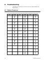
Display Characters ........................................................................................................... 70
Display Symbols .............................................................................................................. 71
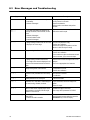
Error Messages and Troubleshooting .............................................................................. 72
Replacement Parts .......................................................................................................... 73
4
PS-USB Service Manual
PS-USB Service Manual
5
1
General Information and Warnings
1.1
About this Manual
This manual is divided into chapters by the chapter number and the large text at the top
of a page. Subsections are labeled as shown by the 1 and 1.1 headings shown above.
-The names of the chapter and the next subsection level appear at the top of alternating
pages of the manual to remind you of where you are in the manual. The manual name
and page numbers appear at the bottom of the pages.
1.1.1 Text Conventions
The keys used to interface with the PS-USB are located on the front panel of the
indicator. The keystrokes are shown in BOLD encased between brackets. (e.g.
[ZERO])
Displayed messages appear in seven segment display type and reflect the case of the
displayed message. (e.g. config)
1.1.2 Special Messages
Examples of special messages you will see in this manual are defined below. The
signal words have specific meanings to alert you to additional information or the relative
level of hazard.
CAUTION!
This is a Caution symbol.
Cautions give information about procedures that, if not observed, could result
in damage to equipment or corruption to and loss of data.
ELECTRICAL WARNING!
THIS IS AN ELECTRICAL WARNING SYMBOL.
ELECTRICAL WARNINGS MEAN THAT FAILURE TO FOLLOW
SPECIFIC PRACTICES OR PROCEDURES MAY RESULT IN
ELECTROCUTION, ARC BURNS, EXPLOSIONS OR OTHER HAZARDS
THAT MAY CAUSE INJURY OR DEATH.
NOTE: This is a Note symbol. Notes give additional and important information, hints
and tips that help you to use your product.
6
PS-USB Service Manual
1.2
Warnings
ELECTRICAL WARNING!
RISK OF ELECTRICAL SHOCK: DISCONNECT ALL POWER SOURCES
BEFORE MAKING CABLE CONNECTIONS TO THE FLOOR SCALE
PLATFORM OR INDICATOR.
FOR USE IN DRY ENVIRONMENTS ONLY.
CAUTION!
The floor scale platform is very heavy. Use appropriate lift equipment.
Scale platform must be installed on a foundation capable of safely supporting
the weight of the floor scale plus the weight of the maximum load.
Do not operate in hazardous areas.
PS-USB Service Manual
l
Read and understand all operating instructions before using this product.
Keep this manual for future reference.
l
Record the weight shortly after placing a load on the platform. After extended
periods, the loadcell output signal may result in a less accurate reading.
l
Avoid extended exposure to extreme heat or cold. Optimum operation is at
normal room temperature. See operating temperature range in the
specifications table. Allow the scale to acclimate to room temperature before
using.
l
Allow sufficient warm up time. Turn the scale on and allow up to 2 minutes
for internal components to stabilize before weighing.
l
Electronic scales are precision instruments. Do not operate near cell
phones, radios, computers or other electronic devices that emit radio
frequencies that may cause unstable readings.
l
This equipment has been tested and found to comply with the limits for a
Class A digital device, pursuant to Part 15 of the FCC Rules. These limits
are designed to provide reasonable protection against harmful interference
when the equipment is operated in a commercial environment. This
equipment generates, uses, and can radiate radio frequency energy and, if
not installed and used in accordance with this manual, may cause harmful
interference to radio communications. Operation of this equipment in a
residential area is likely to cause harmful interference, in which case the
user will be required to correct the interference at their own expense.
7
l
1.3
Avoid using in heavy vibration or heavy airflow conditions. This also applies
when the floor scale is integrated into conveying systems.
Routine Maintenance
IMPORTANT: This equipment must be routinely checked for proper operation
and calibration.
Application and usage will determine the frequency of calibration required for
safe operation.
Always turn off the machine and isolate from the power supply before starting any
routine maintenance to avoid the possibility of electric shock.
1.4
Sharp Objects
Do not use sharp objects such as screwdrivers or long fingernails to operate the keys.
1.5
Cleaning the Indicator
Table 1.1 Cleaning DOs and DON’Ts
DO
DO NOT
Wipe down the outside of standard products Attempt to clean the inside of the indicator
with a clean cloth, moistened with water and Use harsh abrasives, solvents, scouring cleaners or
a small amount of mild detergent
alkaline cleaning solutions
Spray the cloth when using a proprietary
cleaning fluid
1.6
Spray any liquid directly on to the display window
CE Certification
Pending
8
PS-USB Service Manual
2
Installation
DANGER: RISK OF ELECTRICAL SHOCK. BE SURE TO UPLUG THE
INDICATOR BEFORE REMOVING THE COVER OR OPENING THE UNIT.
REFER TO QUALIFIED SERVICE PERSONNEL FOR SERVICE.
2.1
2.2
2.3
Contents
l
Scale
l
6' USB cable
l
AC120V/DC6V 500mA UL adapter
l
RS232 cable
l
Quick Guide & Service Manual
Unpacking and Installation
1.
Unpack the scale and all components from the shipping box.
2.
Place the scale in the desired location.
3.
Lift the stainless steel platform top off the base.
4.
Adjust the feet to center the level bubble.
5.
Once the scale is level, reinstall the stainless steel platform top
6.
Install the batteries or plug in the adapter.
Legal for Trade
The PS-USB indicator and platform are NTEP certified, making the scale capable of
being used in Legal for Trade applications. However, the scale is not a Legal for Trade
until it has been certified and registered by an authorized Weights and Measures agent.
See www.ncwm.net/content/regions for a listing of registered US Weights and Measure
offices by state.
PS-USB Service Manual
9
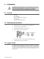
2.4
Connectors and Jumpers
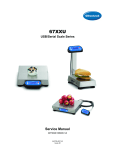
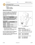
There are connectors located on the side of the scale for the power supply, USB port,
RS-232 serial port and display which is used for mounting the display remotely on a
wall or a desk.
Figure 2.1 View of Scale Connectors
2.4.1 Power Supply
The PS-USB comes with an external AC to DC power adapter. Simply plug the AC
adapter into the DC6V power jack on the scale and then plug into a standard wall outlet.
IMPORTANT: Make sure that the AC voltage and polarity appearing at the wall
outlet matches the input voltage as well as the polarity marked on the AC
adapter.
2.4.2 Definition of Connectors and Jumpers
Table 2.1 Loadcell Connector
10
Pin
Description
In/Out/Power
Electrical Level
1
+ excitation
power output
5±0.3 VDC (≤0.12A)
2
+ sense
power input
5±0.3 VDC
3
- excitation
power ground
0 VDC
4
- sense
power input
≤0.5 VDC
5
+ signal
signal input
2.5±0.3 VDC
6
- signal
signal input
2.5±0.3 VDC
7
shield
-
-
PS-USB Service Manual
Table 2.2 Adapter Power Input Connector (ADP)
Pin #
Definition
In/Out/Power
Electrical Level
1
Adapter input voltage +
Power input
6.5 VDC (6-9VDC, ≥0.5A)
2
Adapter input voltage - (GND)
Power output
0VDC
Table 2.3 Battery Input Power Connector (BAT)
Pin #
Definition
In/Out/Power
Electrical Level
1
Battery input voltage + Power
Input
4-6.8Vdc
2
Battery input voltage - (GND)
Power ground
0Vdc
3
Temperature sensor on Battery input
Power ground
-
Table 2.4 USB Connector for Virtual RS-232 Com1 and Power Supply (J1)
Pin #
Definition
In/Out/Power
Electrical Level
Power output
5±0.3 VDC
1
VDD
2
RXD Receive on UART1
Input
0-5VDC
3
TXD Transmit on UART1
Output
0-5VDC
4
GND of VDD
Power ground
0VDC
5
GND1 of VUSBH
Power ground
0VDC
6
USB Power DC/DC select
Output
0-5VDC
7
USB Power DC/DC output
output
6±0.3 VDC
Table 2.5 Serial Input / Output Connector (SIO)
Pin #
Definition
Electrical Level
Input/output
0-5VDC
1
RS485 signal A (if RS485 installed)
2
RS232 Transmit on UART0
Output
-12 to +12VDC
3
RS232 Receive on UART0
Input
-12 to +12VDC
-
-
Power ground
0VDC
4
5
GND
6
-
-
-
7
-
-
-
8
-
-
-
Input/output
0-5VDC
9
PS-USB Service Manual
In/Out/Power
RS485 signal B (if RS485 installed)
11
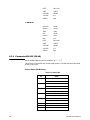
Table 2.6 KCAK Jumper Set
Connected Pins
Function
1-2
Calibration enabled
2-3
Calibration disabled
Table 2.7 JP1 Jumper
12
Connected Pins
Function
1-2
Pins 1-2 are shorted for 4 wire load cell
2-3
Pins 2-3 are shorted for 6 wire load cell
PS-USB Service Manual
3
Scale Operation
To set up the indicator, you must first enter the appropriate menu mode. The front panel
keys become directional navigators to move around in the menus. See Table 3.2 for
details.
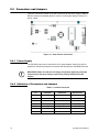
3.1
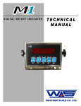
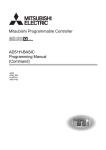
Front Panel
The front panel incorporates the display and keypad.
The annunciators used are incorporated in the display. The annunciator will be lit went
the mode is active.
Figure 3.1 PS-USB Keypad and Display
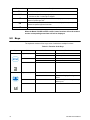
Table 3.1 LCD Display Annunciators and Definitions
LCD Annunciator
Description
Better known as the "Center of Zero" annunciator. It is lit when the scale is at the zero point
and the gross weight is 0.
Scale is stable
Battery level
NET
Total
Peak
lb
oz
kg
%
PS-USB Service Manual
Indicates net mode and the tare weight is not 0.
Display data is accumulated total times, weight, pieces, or percentage.
Scale is in dynamic weighing mode. Hold type is PEAK-HOLD.
Indicates the current unit of measure is lb.
Indicates the current unit of measure is oz.
Indicates the current unit of measure is kg.
Measure unit is% (in percentage weighing mode).
13
LCD Annunciator
Pcs
Hold
Description
Indicates counting mode. Unit of measure is pieces.
- Hold flashes - actual fluctuating weight displayed.
- Hold does not flash - locked weight is displayed.
HI
Data compare (check-weighing) is enabled. Current data (weight, pieces, or percent) is
above the specified upper limit.
OK
Indicates when data compare is enabled and current data (weight, pieces or percent) is
between the specified upper and lower limits.
LO
Data compare is enabled. Current data is below the specified lower limit.
When the Model PS-USB is NTEP certified, some functions will not be enabled
and the corresponding annunciator will not be displayed.
3.2
Keys
The keyboard consists of four keys, some of which have multiple functions.
Table 3.2 Function of the Keys
Key
Mode
Condition
Weigh, count, or percent Press for less than 3 seconds
Input data mode
Menu selection mode
Enter or exit HOLD mode
Press for more than 3 seconds
Enter Setup mode
Press for more than 3 seconds
Input decimal point
Press for less than 3 seconds
Return to last sub-menu
-
Weigh, count, or percent Press for less than 3 seconds
Press for more than 3 seconds
14
Function
Return to last sub-menu
Sends output data via the serial port
Selects mode: Weighing, Counting, or
Percent
Input data mode
-
Increases the digit in the flashing data entry
position by one
Menu selection mode
-
Returns to last item of current sub-menu
PS-USB Service Manual
Key
Mode
Condition
Weigh, count, or percent Press for less than 3 seconds
ACC
TOTAL
Press for more than 3 seconds
Adds accumulation values to memory;
displays instances and totals
Displays accumulation instances and totals
Input data mode
-
Decreases the digit in the flashing data entry
position by 1
Menu selection mode
-
Goes to next item of current sub-menu
Weigh mode
Press for less than 3 seconds
Changes weighing unit of measure
Count or percent
Press for less than 3 seconds
Enters the sub-menu to input piece weight for
counting or to enter reference weight for
percent-weighing
UNIT
Weigh, count, or percent Press for more than 3 seconds
Enters the sub-menu to input the comparative
data range for check-weighing
Time and date mode
Enters time or date setting mode
Press for more than 3 seconds
Input data mode
-
Shifts the flashing data entry position from
right to left
Menu selection mode
-
Advances to next item of current sub-menu
Weigh, count, or percent Press for less than 3 seconds
Press for more than 3 seconds
TARE
Function
Tare the weight
Enters predetermined tare input mode
Input data mode
-
Confirms the input data and forwards to next
step
Menu selection mode
-
Confirms the input data and forwards to next
step
Power off mode
-
Power on
Weigh, count, or percent Press for less than 3 seconds
Press for more than 3 seconds
Zero function
Power off
Input data mode
-
Ignore current operation
Menu selection mode
-
Exit from current working mode
NOTE: To access the second function of the key, press and hold the key for more
than 3 seconds.
PS-USB Service Manual
15
3.3
Turn the Scale ON
Turn on the scale by pressing the ZERO/ON/OFF key.
3.4
Turn the Scale OFF
Turn the scale off pressing and holding the ZERO/ON/OFF key for 4 seconds.
3.5
Navigating the Weigh Mode
3.5.1 Changing the Working Mode
Press and hold the [PRINT/FUNC] key, then use
confirm to enter into weighing mode or counting mode.
key to choose and
3.5.2 Normal Weighing Mode
1.
Turn on the scale by pressing the ZERO/ON/OFF key.
If the display stabilizes but doesn't show zero, press the ZERO/ON/OFF
key to set a new zero point.
2.
Place objects on the scale platform. The weight will be displayed.
NOTE: Objects should be placed at the center of the platform. Corner or side loading
heavy objects may risk overloading an individual load cell and damage the scale.
3.
To change the weight unit of measure, press the UNIT/DATA key.
NOTE: Under certain conditions, g and lb:oz are not available. In trade applications,
lb:oz should be prohibited. Please refer the following tables (3.3 and 3.4)
4.
To send data to another device via the serial port, press the PRINT/FUNC key.
3.5.3 Zero
If the display does not show 0 and there is no weight on the platform, press the ZERO/
ON/OFF key to zero the reading.
Zero range: ±2% * full Capacity.
The zero function is unavailable when the displayed reading is out of the zero range.
The indicator will show one of the following error messages:
0----- Over zero range
16
PS-USB Service Manual
0_____
Under zero range
3.5.4 Setting a Tare Weight
1.
Zero the scale by pressing the ZERO/ON/OFF key.
2.
Place an empty container on the platform. Press the TARE/PRESET key.
The display will return to zero, eliminating the weight of the container.
The "NET" annunciator will be lit on the display.
3.
Place the material or object to be weighed in the container.
The net weight will be displayed.
4.
To exit the tare mode, remove all weight from the scale.
The display will show a negative weight.
5.
Press the TARE/PRESET key to return the display to zero.
3.5.5 Setting a Pre-determined Tare Weight
1.
Zero the scale by pressing the ZERO/ON/OFF key.
2.
Press and hold the TARE/PRESET key until Pr.Tare is displayed.
The tare weight will be displayed. The first digit and NET will flash on the
display.
3.
Enter the tare weight using the
keys. After inputting the tare
weight, press the TARE/PRESET key to confirm.
The "NET" annunciator will be lit in the display.
NOTE: Tare weight must be greater than zero and no more than the maximum scale
capacity.
4.
Place the material or object to be weighed onto the scale platform.
The net weight will be displayed.
5.
To exit tare mode, remove all weight from the scale. The display will show a
negative weight. Press the TARE/PRESET key to return the display to zero.
NOTE: Note: This indicator can only save one tare weight. The new tare weight will
automatically replace the old one. Pre-determined tare will be lost after the scale is
turned off.
3.5.6 Change Weight Unit
Press the [UNIT/DATA] key to select kg, lb, oz, lb:oz, g. Note: under some conditions
oz, lb:oz, g are not available. Please refer the following tables.
PS-USB Service Manual
17
Table 3.3 Use kg as Primary Unit
Display Division Value
Calibration
Division Value
kg
g
lb
oz
lb:oz
0.0001 kg
0.0001 kg
0.1 g
0.0002 lb
0.005 oz
Not available
0.001 kg
0.001 kg
1g
0.002 lb
0.05 oz
Not available
0.01 kg
0.01 kg
10 g
0.02 lb
0.5 oz
0.5 oz
0.1 kg
0.1 kg
Not available
0.2 lb
5 oz
Not available
1 kg
1 kg
Not available
2 lb
Not available
Not available
10 kg
10 kg
Not available
20 lb
Not available
Not available
0.0002 kg
0.0002 kg
0.2 g
0.0005 lb
0.01 oz
Not available
0.002 kg
0.002 kg
2g
0.005 lb
0.1 oz
0.1 oz
0.02 kg
0.02 kg
20 g
0.05 lb
1 oz
1 oz
0.2 kg
0.2 kg
Not available
0.5 lb
10 oz
Not available
2 kg
2 kg
Not available
5 lb
Not available
Not available
20 kg
20 kg
Not available
50 lb
Not available
Not available
0.0005 kg
0.0005 kg
0.5 g
0.001 lb
0.02 oz
Not available
0.005 kg
0.005 kg
5g
0.01 lb
0.2 oz
0.2 oz
0.05 kg
0.05 kg
50 g
0.1 lb
2 oz
2oz
0.5 kg
0.5 kg
Not available
1 lb
Not available
Not available
5 kg
5 kg
Not available
10 lb
Not available
Not available
50 kg
50 kg
Not available
Not available
Not available
Not available
Table 3.4 Use lb as Primary Unit
18
Display Division Value
Calibration
Division Value
kg
g
lb
oz
lb:oz
0.0001 lb
Not available
Not available
0.0001lb
0.002 oz
Not available
0.001 lb
0.0005 kg
0.5 g
0.001 lb
0.02 oz
Not available
0.01 lb
0.005 kg
5g
0.01 lb
0.2 oz
0.2 oz
0.1 lb
0.05 kg
50 g
0.1 lb
2 oz
2 oz
1 lb
0.5 kg
Not available
1 lb
Not available
Not available
10 lb
5 kg
Not available
10 lb
Not available
Not available
0.0002 lb
0.0001 kg
0.1 g
0.0002 lb
0.005 oz
Not available
0.002 lb
0.001 kg
1g
0.002 lb
0.005 oz
Not available
0.02 lb
0.01 kg
10 g
0.02 lb
0.5 oz
0.5 oz
0.2 lb
0.1 kg
Not available
0.2 lb
5 oz
Not available
2 lb
1 kg
Not available
2 lb
Not available
Not available
20 lb
10 kg
Not available
20 lb
Not available
Not available
0.0005 lb
0.0002 kg
0.2g
0.0005 lb
0.01oz
Not available
PS-USB Service Manual
Display Division Value
Calibration
Division Value
kg
g
lb
oz
lb:oz
0.005 lb
0.002 kg
2g
0.005 lb
0.1oz
0.1 oz
0.05 lb
0.02 kg
20g
0.05 lb
1oz
1 oz
0.5 lb
0.2 kg
Not available
0.5 lb
10oz
Not available
5 lb
2 kg
Not available
5 lb
Not available
Not available
50 lb
20 kg
Not available
50 lb
Not available
Not available
3.5.7 Output Data (print to a computer or printer)
When scale is stable press the [PRINT] key.
3.5.8 Display Gross or Net Weight
l
If the tare weight is not zero, the Net weight will be displayed.
l
If the tare weight is zero, Gross weight will be displayed.
3.5.9 Check Weight (data compare)
The check weighing or data compare function allows the user to enter a pre-set range.
The display will indicate whether the weighed value is within that range and indicate if
it is too high or too low.
1.
Press and hold the UNIT/DATA key for 4 seconds to enter the comparative data
range.
UNIT.LB or UNIT.KG will be displayed first.
2.
Use the UNIT/DATA keys to select the comparison unit of measure.
3.
Press the TARE/PRESET key to confirm.
HIGH will be shown quickly. The last Hi limit value will be displayed (the
default value is 000000). The HI annunciator will be lit on the display.
4.
Use the
keys to enter the upper limit of the range.
5.
Press the TARE/PRESET key to confirm and move to the next step.
Low will be displayed quickly. The last Lo limit value will be displayed
(the default value is 000000). The LO annunciator will be lit on the
display.
PS-USB Service Manual
6.
Use the
keys to enter the lower limit of the range.
7.
Press the TARE/PRESET key to confirm.
8.
Press ZERO/ON/OFF key to exit and go back to the normal weighing mode.
19
NOTE: If the upper limit is 0, or if it is less than the lower limit, check weighing mode
will automatically be exited.
9.
After an acceptable range has been set, check weighing may begin.
If the weighed value is within the specified range, OK will be displayed
on the indicator and an audible beep will sound.
If the value is outside the specified range, HI or LO will be displayed
with no audible beep.
10.
3.6
To turn check weighing off, follow the above instructions and change the upper
limit to zero.
Accumulation Mode
The accumulation function allows storage of weighed values and the sums those
values. This function can accumulate weights, piece counts, and percentages in
normal weighing mode, counting mode, and percent weighing mode.
1.
With a load on the scale, press the ACC/TOTAL key to add the displayed value
to the accumulated total.
The indicator will first display the number of accumulations (e.g. if this is
the 5th accumulated value, it will display ACC.005).
The accumulated sum total thus far will be displayed and then the load
weight will be displayed.
NOTE: Only loads exceeding the minimum weight (default of 10d, where d = the
scale's readability, see specifications) can be accumulated. This setting (USEROTHER-NLD.RNG) can be modified from its default within User Setup mode, but
changes will impact other functions such as HOLD.
2.
Remove the load and place another load to continue accumulating
3.
Press and release the ACC/TOTAL key to add the new value.
NOTE: To avoid duplicating a value for a same load, the accumulation function
requires the original load to be removed before a new value can be accumulated.
20
PS-USB Service Manual
4.
To view the total accumulated data at any time, press and hold the ACC/
TOTAL key for 4 seconds.
The number of accumulations and the accumulated sum total will be
alternately be displayed (weight or quantity) until the ACC/TOTAL key is
pressed again.
The number of accumulations and total values can be displayed or sent
to another device via the serial port by pressing and releasing the
PRINT/FUNC key.
5.
To clear and reset the accumulated data, press and release the ZERO/ON/
OFF key while total accumulated data and the accumulated sum total are
alternatively displayed.
NOTE: When the HOLD function is enabled and working in PEAK HOLD mode, the
Accumulation function will automatically be disabled.
3.7
Count Mode
The counting function calculates and displays the piece quantity of the load that has
been weighed.
1.
From normal weighing mode or percent-weighing mode, press and hold the
PRINT/FUNC key for 4 seconds.
2.
Use the
3.
Press the TARE/PRESET key to confirm and access the counting mode.
keys to select COUNT.
NOTE: In counting mode, the ZERO, TARE, PRINT, HOLD, PRESET TARE, ACC,
SETUP, and ON/OFF functions are all available.
There are two ways to enter the piece weight. Find the preferred method and follow the
instructions below.
3.7.1 Enter a Known Piece Weight Directly
1.
Press the UNIT/DATA key.
2.
When InP.PWt is displayed, press the TARE/PRESET key to access the
"Input Piece Weight" mode.
NOTE: At any time you can press ZERO/ON/OFF to exit "Input Piece Weight" and
return to counting mode.
PS-USB Service Manual
21
3.
When UNIT.KG is displayed, use the
weight unit of measure.
4.
Press the TARE/PRESET key to confirm.
keys to select the piece
The previously entered piece weight will be shown (the default value is
000000).
5.
Use the
keys to input a new piece weight.
6.
Press and hold the SETUP key for 4 seconds to input the decimal point.
7.
Press the TARE/PRESET key to confirm and return to counting mode.
NOTE: If the input piece weight is less than 0.5d (where d = the scale's readability,
see specifications), the indicator will display PWt.Er and will automatically return to
counting mode.
3.7.2 Enter the Piece Weight with a Sample of a Known Quantity
1.
Press the UNIT/DATA key.
2.
When InP.PWt is displayed, use
3.
Press the TARE/PRESET key to access the "Get Piece Weight" mode.
keys to select SPL.PWT.
NOTE: At any time you can press ZERO/ON/OFF to exit "Get Piece Weight" and
return to counting mode.
4.
When SPL.Lo is displayed, remove any load from the platform and press the
TARE/PRESET key to confirm.
If the scale hasn't stabilized, SPL.Lo will flash. After it has stabilized, it
will go to the next step.
5.
When SPL.Hi is displayed, place a sample of a known quantity onto the scale
platform and press the TARE/PRESET key.
If the scale hasn't stabilized, SPL.Hi will flash.
If the scale has stabilized, INP.PCS will be displayed quickly and the
previously entered piece weight will be displayed (the default value is
000000, and the position of decimal point is determined by CONFIGFUNC-PERCEN setting).
6.
22
Use the
keys to input the sample quantity.
PS-USB Service Manual
7.
Press the TARE/PRESET key to confirm.
NOTE: If the input piece weight is less than 0.5d (where d = the scale's readability,
see specifications), the indicator will display PWt.Er and will automatically return to
counting mode.
8.
Once an acceptable piece weight has been entered, the scale will return to
counting mode.
NOTE: The piece weight that has been entered will be saved, even after powering off.
The indicator can only save one piece weight.
Entering a new piece weight will automatically replace the old one.
3.8
Check Counts (count compare) in Counting Mode
The Check Counts function allows the user to enter a pre-set range. The display will
indicate whether the weighed value is within that range or indicate if it is too high or too
low.
1.
Press and hold the UNIT/DATA key for 4 seconds to access the comparative
data range.
2.
HIGH will be shown and 000000 will be displayed.
The HI annunciator on the display will be lit.
3.
Use the
keys to input the upper limit of the range (weight, piece
quantity, or percentage depending on initial mode).
4.
Press the TARE/PRESET key to confirm and move to the next step.
5.
Low will be shown and 000000 will be displayed. The LO annunciator on the
display will be lit.
6.
Use the
7.
Press the TARE/PRESET key to confirm.
keys to enter the lower limit of the range.
NOTE: If the upper limit is 0, or if it is less than or equal to the lower limit, check
weighing mode will automatically be exited.
PS-USB Service Manual
23
8.
After an acceptable range has been set, check weighing may begin.
If the weighed value is within the specified range, the OK annunciator on
the display will be lit and an audible beep will be sound.
If the value is outside the specified range, the HI or LO annunciator on
the display will be lit with no audible beep. Audible beep parameters can
be changed from their defaults in User Setup mode.
3.9
Percent Weighing Mode
In this mode, the scale will calculate the weight on the platform and display the
percentage after the unit-percentage-weight of goods is obtained.
NOTE: The Percent Weighing Mode is disabled when legal for trade is enabled.
NOTE: If 100% display format is set to 100%, 100.0% or 100.00% in CONFIG-FUNCPERCEN menu, then the unit-percentage-weight is the weight of 1%, 0.1% or 0.01%.
NOTE: Set CONFIG-FUNC-PERCEN menu to YES for use of the percent weighing
function.
1.
From the normal weighing or counting mode, press and hold the PRINT/FUNC
key for 4 seconds,
WEIGH/COUNT will be displayed.
2.
Use
key to select PERCEN, then press TARE/PRESET to confirm.
Before a new unit-percentage-weight is calculated, the last unitpercentage-weight will be used.
Note: In percent weighing mode, the function of ZERO, TARE, PRINT, HOLD, PRESET
TARE, ACC, SETUP, ON/OFF are available.
3.9.1 Using an Entered Weight and Percentage
The scale calculates the unit-percentage-weight.
24
1.
Press the UNIT/DATA key, when InP.Pct is displayed.
2.
Press the TARE/PRESET key to continue.
3.
Before entering the weight value, use
key to select the percentage
from 1%, 2%, 5%, 10%, 20%, 50% and 100%, corresponding to the weight
that will be entered in the following steps.
PS-USB Service Manual
4.
Press the TARE/PRESET key to confirm the entry.
5.
When UNIT.KG is displayed, use the UNIT/DATA key to select the weight
unit.
6.
Use the TARE/PRESET key to continue.
7.
Press the ZERO/ON/OFF key to exit.
8.
When the last stored unit-percentage-weight data is displayed (the default
value is 000000), use the
weight
key to enter the new unit-percentage-
9.
Press the SETUP key for more than 4 seconds to enter the decimal point.
10.
Press the TARE/PRESET key to confirm, save, and to return back to percent
weighing mode.
If the calculated unit-percentage-weight is less than 0.5d, the indicator
will display Pct.Er and return back to percent weighing mode.
3.9.2 Using Weight Samples when Percentage is Known
PS-USB Service Manual
1.
Press the UNIT/DATA key when InP.Pct is displayed.
2.
Use the
key to select SPL.Pct, then press the TARE/PRESET
key to weigh samples (when the percentage is known), and to calculate the
piece weight.
3.
Press ZERO/ON/OFF key to exit and return to percent weighing mode.
4.
When SPL.Lo is displayed, remove all samples from the scale and press the
TARE/PRESET key to confirm.
5.
Before the scale is stable, SPL.Lo will flash on the display. When the scale
becomes stable, continue to the next step.
6.
Press the ZERO/ON/OFF key to exit and return to percent weighing mode.
7.
When SPL.Hi is displayed, place samples (when the percentage is known)
onto the scale.
8.
Press the TARE/PRESET key to confirm reading weight. Before the scale is
stable, SPL.Hi will flash on the display. When the scale becomes stable,
continue to the next step.
9.
Press the ZERO/ON/OFF key to exit and return to percent weighing mode.
10.
After INP.PCT is displayed quickly, the previously entered percent will be
displayed. (the default value is 000000, and the position of decimal point is
determined by CONFIG-FUNC-PERCEN setting,
25
11.
Use the
key to input the percentage of samples and press the
TARE/PRESET key to confirm.
If the calculated unit-percentage-weight is less than 0.5d, the indicator
will display Pct.Er and return to percent weighing mode. Otherwise,
after the reasonable unit-percentage-weight is calculated, the scale will
return to percent weighing mode.
The calculated unit-percentage-weight can be saved when the scale has
been powered off and it can be used the next time the scale is powered
on.
3.9.3 Check Percent (percentage compare)
The high and low limitation of percentage should be set according to following steps.
NOTE: Set CONFIG-FUNC-COMPAR menu to YES for use of the percent weighing
compare function.
1.
In percent weighing mode, press the UNIT/DATA key for more than 4 seconds
to enter compare data (high and low values).
2.
After HIGH is displayed, 000000 will then be displayed. Use the
key to enter the high percentage number and press the TARE/
PRESET key to confirm.
The HI annunciator will illuminate.
3.
Press the ZERO/ON/OFF key to exit and return to percent weighing mode.
4.
After Low is displayed quickly, 000000 will then be displayed. Use the
key to enter the low percentage number and press the TARE/
PRESET key to confirm.
The LO annunciator will illuminate.
5.
Press the ZERO/ON/OFF key to exit and return to counting mode.
NOTE: If the high number is 0 or is equal or less than low number, the comparison will
be disabled.
6.
26
After a reasonable limitation is set and compare is active, one of annunciators
HI, OK, LO will be displayed, and the beeper will sound according to the
setting in USER-BEEP.
PS-USB Service Manual
3.10 BMI Working Mode
NOTE: The BMI Working Mode is disabled when legal for trade is enabled.
NOTE: Set CONFIG-FUNC-BMI menu to YES for use of the BMI working mode
function.
1.
To enter BMI Working mode, CONFIG-FUNC-ACCUMU= Yes:
2.
If In normal weighing mode, percent weighing mode, or counting mode, press
and hold the FUNC key for 4 seconds.
One of the following will be displayed (WEIGH / COUNT / PERCENT)
depending on the mode that was set previously.
3.
Use the
BMI mode.
key to select BMI, then press TARE/PRESET to confirm
When the scale enters this mode, "CM.xxx" (means: last input height is
xxx cm) or "IN.xx.x" (means: last input height is xx.x inch) will be
displayed, and to wait for input height.
3a.
To change height unit to cm or inch, press the UNIT/DATA key.
3b.
To change height number, use the
3c.
To quickly increase or decrease the number, press and hold PRINT/FUNC or
ACC/TOTAL key.
4.
Press the TARE/PRESET key to confirm the input.
5.
Press the ZERO/ON/OFF key to exit input data mode and return to BMI
working mode.
keys.
The range of height is 50-250cm (19.7-98.4inch) and default is
170cm(66.9inch)
PS-USB Service Manual
6.
In this mode, when BMI number is displayed (BMI annunciate is also lit), or
weight number is shown (BMI and kg or lb annunciators are lit), press the
ACC/TOTAL key to select weight or BMI number to be displayed.
7.
When the weight is displayed, the unit can be selected by pressing the UNIT/
DATA key. The BMI and weight unit will be displayed at same time.
8.
In this mode, when current net weight is less than NLD.RNG, the indicator will
go to the display weight number if CONFIG-FUNC-ACCUMU= No; or the
indicator will return to original working mode if CONFIG-FUNC-ACCUMU=
Yes.
27
3.11 Weight Fine-tune
With this function, the user can adjust the displayed weight (to a minimal extent) with
no need for standard weight.
NOTE: The Weight Fine-tune Mode is disabled when legal for trade is enabled.
NOTE: The scale must have been calibrated before this adjustment.
NOTE: The range of adjustment is "(current displayed weight) x (0.9-1.1)". This
means the range is about ±10%.
NOTE: The "CONFIG-REGULA =NONE" and "CONFIG-FUNC-WT.ADJ=YES" must
be set.
1.
In normal weighing mode, place a load onto scale. For example 1230.0
The indicator will display the weight (for example 1234.5). Press the
TARE/PRESET and ZERO/ON/OFF keys at same time until first digit
flashes, which means indicator has entered into "weight fine-tune"
mode.
2.
Use the
1230.0).
key to enter the correct weight (the load weight e.g.
3.
Confirm by pressing the TARE/PRESET key.
The active correct weight will be displayed and the digits will no longer
be flashing. The displayed weight will be adjusted by this ratio (1230.0/
1234.5) and this ratio will be active until the next modification.
To remove effect of this ratio, follow one of the two options below:
1.
Perform standard calibration, refer to the section on "CALIBRATION".
2.
Remove weight from the scale and press the ZERO/ON/OFF key to display 0.
3.
Place a load onto the scale.
A number will be displayed (for example it displayed 1230.0 lb but the
original number is 1234.5).
4.
28
Press the TARE/PRESET and ZERO/ON/OFF at the same time until first digit
flashes, which means indicator has entered into "weight fine-tune" mode.
PS-USB Service Manual
5.
Press the SETUP key for the displayed weight to be restored to 1234.5, and
then press the TARE/PRESET key to confirm and exit to normal weighing
mode.
3.12 HOLD Function
HOLD function can be used to freeze the display number. In this mode, the scale can
catch a dynamic number, hold a stable number, or average an unstable number and
HOLD (freeze) this number temporary for the user to watch or record.
In Positive or Negative Peak HOLD mode, the PEAK and HOLD annunciator will be lit,
and for other HOLD modes, the HOLD annunciator will be lit. When HOLD annunciator
is flashing, the displayed number is live. When HOLD annunciator becomes steady, the
displayed number is frozen.
This function can be used in normal weighing mode, counting mode and percent
weighing mode. After entering HOLD mode, the A/D converter speed can be increased
to 80Hz (if USER-HOLD-AD.H.SPD is set to YES) from the original 10Hz for some
dynamic weighing applications.
With the HOLD function, it is possible to weigh restless weighing samples such as live
animals or moving objects. The indicator provides a special mode setting to
accommodate movement in weight.
NOTE: The Hold Function is disabled when legal for trade is enabled.
1.
For the HOLD function to be active, the CONFIG-FUNC-HOLD menu item must
be set to YES. Menu items of USER-HOLD-HLD.MOD /-AVG.TIM /-HLD.TIM /STB.TIM, USER-OTHER-NLD.RNG need be set to reasonable values.
2.
To increase the speed for sampling of weight, set USER-HOLD-AD.H.SPD
menu item to YES.
3.
To enter HOLD working mode, press the SETUP key when scale is in normal
weighing mode, counting mode or percent weighing mode.
There are several HOLD modes use to freeze display data:
l
Positive Peak Number HOLD mode
l
Negative Peak Number HOLD mode
l
Toggle HOLD mode
l
Average HOLD mode
l
Auto HOLD mode
Refer to the following sections for information on the available HOLD modes.
3.12.1 Positive Peak HOLD
When USER-HOLD-HLD.MOD is set to PS.PEAK, the hold mode is positive peak hold
mode. When the scale first enters this working mode, it will display the largest positive
number that is from the time of zero-point set.
PS-USB Service Manual
29
After entering this working mode, the scale will always capture and refresh with the
largest positive number. To exit the HOLD mode, press the SETUP key.
3.12.2 Negative Peak HOLD
When USER-HOLD-HLD.MOD is set to NG.PEAK, the hold mode is negative peak hold
mode. When the scale first enters this working mode, it will display the largest negative
number that is from the time of zero-point set.
After entering this working mode, the scale will always capture and refresh with the
largest negative number. To exit HOLD mode, press the SETUP key.
3.12.3 Toggle HOLD
When USER-HOLD-HLD.MOD is set to TOGGLE, the hold mode is toggle in hold
mode. After entering this working mode, the scale will freeze and display the number if
the scale is stable. Only the weight that is over USER-OTHER-NLD.RNG (zero 'dead'
band ) can be held.
To exit HOLD mode, press the SETUP key. If the length of time that the scale is
unstable for more than USER-HOLD-STB.TIM, STB.ER will be displayed. Press the
TARE/PRESET key to start averaging again, or press the SETUP key to exit.
3.12.4 Average HOLD
When USER-HOLD-HLD.MOD is set to AVERAG, the hold mode is average hold
mode. After entering this working mode, the scale will freeze and display number if the
scale is stable. If the scale is not stable, but the variation is less than USER-HOLDHLD.RNG, the scale will average data in USER-HOLD-AVG.TIM, then freeze and
display the number. Only the weight that is over USER-OTHER-NLD.RNG can be
frozen. Scale will exit HOLD mode according to the setting of USER-HOLD-HLD.TIM.
If the time of scale variation is over USER-OTHER-NLD.RNG or is more than USERHOLD-STB.TIM, STB.ER will be displayed. Press TARE/PRESET, UNIT/DATA, ACC/
TOTAL or PRINT/FUNC to start averaging again, or press SETUP key to exit.
3.12.5 Auto HOLD (default setting)
When USER-HOLD-HLD.MOD is set to AUTO, the hold mode is auto hold mode.
Different subjects can be weighed one after another without pressing any buttons. After
entering this working mode, the scale will freeze and display the number if the scale is
stable. If the scale is not stable, but the variation is less than USER-HOLD-HLD.RNG,
the scale will average data in USER-HOLD-AVG.TIM, then freeze and display the
number. Only the weight that is over USER-OTHER-NLD.RNG can be frozen. If the
held weight is removed, and a new load is placed on the scale, the scale will
automatically hold the new number of the load.
The scale will exit HOLD mode according to the setting of USER-HOLD-HLD.TIM. If
the time of scale variation is over USER-OTHER-NLD.RNG or is more than USERHOLD-STB.TIM, STB.ER will be displayed. Press the TARE/PRESET key to start
averaging again, or press SETUP key to exit.
30
PS-USB Service Manual
4
Setup Mode
The setup menu consists of five different sub-menus. Within each sub-menu are
different menu options.
The config/cal switch must be set in the ON position in order to make changes to
specific parameters.
4.1
4.2
Entering the Setup Menu
1.
Power on the indicator by pressing and holding the ZERO/ON/OFF/ key.
2.
Press the SETUP key for 3 seconds. The indicator shows config to indicate
the Setup Menu mode has been entered.
3.
In the Setup mode, use the arrow keys to select a menu item. Press the TARE/
PRESET key to enter the parameter.
4.
Press the
key to select the sub-menu item, to select a choice, to
set a number, to confirm and save data, and/or to exit this mode.
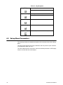
Navigating the Setup Menu
CONFIG
PS-USB Service Manual
USER
CAL
MISC
TEST
1.
Once Config is displayed, use the [UNIT] key to move to forward through
the menu choices or the [HOLD] key to move backward in the setup menu.
2.
Use the [TARE] key to access the desired menu. (e.g. User)
3.
Use the [UNIT] key to view the available sub-menus (parameter: e.g. beep).
4.
Use the [TARE] key to select the sub-menu.
5.
Use the [UNIT] key to view the choices within the sub-menu. (e.g. key)
6.
Press the [TARE] key to select the desired choice within the sub-menu. Once
selected the parameter will be displayed.
7.
Press [ZERO] to return back up and return to the setup menu.
31
Table 4.1 Key Navigation
[SETUP]
Access the Setup Menu
Returns to last sub-menu
[PRINT / FUNC]
Scroll through available menus
Return to last item of current sub-menu
4.3
[ACC / TOTAL]
Advance to next item of current sub-menu
[UNIT / DATA]
Advance to next item of current sub-menu
[UNIT / DATA]
Confirm data input and advances to the next step
Setup Menu Parameters
This section provides more detailed descriptions of the selections found in the Setup
Menu.
The menu charts show the flow of the parameters and also provide a quick reference
to the parameters within the menu.
The menu tables show the sub-menus, options and default parameter in LCD display
format to coincide with the actual display.
32
PS-USB Service Manual
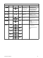
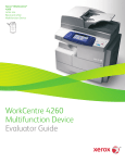
4.3.1 CONFG Menu
CFG.ON
CFG.OFF
RESET
No
REGULA
PRIM.N
Yes
PRIM.D
100 – 100,000
kg
none
10N.DSP
No
Yes
USA
Canada
IN.IZSM
OV.IZSM
0 - 100
MOTION
OVER.LD
1 - 255
0 - 100
0.0001
0.0002
0.0005
0.001
0.002
0.005
0.01
0.02
0.05
0.1
0.2
0.5
1
2
5
10
20
50
AD.FROM
ADC
AD.H.SPD
COM2
Yes
UNITS
0-6
No
FUNC
FILTER
SAZSM
AZSM
0 - 100
FLT1.TH
FLT1.ST
FLT2.TH
FLT2.ST
0 - 255
1 - 64
0 - 255
0 - 255
0 - 100
WEIGHT
100 – 125,000
lb
Europe
ZRO.PNT
IZSM
SECND.N
PRIM.UT
HOLD
Yes
COUNT
BMI
No
CAL.ZRO
ACCUMU
Yes
No
WT.ADJ
No
Yes
NO
WEIGHT
ACCUMU
No
Yes
DSP.OVR
COMPAR
Yes
Yes
CAL.ZRO LST.Z.T
PERCNT
MANUAL
No
AUTO
No
LST.Z.T
NO
100%
100.0%
100.00%
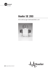
Figure 4.1 CONFG Menu Chart
The figure above is an illustration of the available menus with the CONFG menu and
the choices within those menus. Refer to Table 4.2 for explanations of the menu
choices.
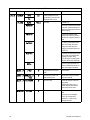
Table 4.2 CONFG Menu Choices and Explanations
CONFG
SubMenu1
SubMenu2
Option
CFg.ON
CFg.OFF
RESET
NO
Default
on
Seal switch position
NO
Reset Confg menu
parameters to default
setting
USA
Select the standard in
which the scale will
comply: USA, Canada,
Europe
YES
REGULa
none
USA
Canada
Parameter Description
Comment
The display will show whether the
seal switch is in the ON or Off
position. This parameter can’t be
changed within the software.
*None = not legal for trade.
Europe
PS-USB Service Manual
33
CONFG
SubMenu1
SubMenu2
Option
Default
PRIM.N
100 100000
3000
Primary full scale value
Default full scale value will depend
on capacity of scale.
*If (REGULA) ≠ none, the max is
10,000
PRIM.D
0.0001
0.05
The division value under
primary unit
Default division size will depend on
capacity of scale.
The division value under second
unit is automatically determined by
the indicator according to the
division value under primary unit.
Primary unit
Select the primary unit from kg or lb.
The second unit is lb if kg is
selected as the primary unit.
*The calibration standard weight
must be in the primary unit!
Second scale full scale
value
The division number under second
unit. The maximum is
1.25*(PRIM.N).
*If (REGULA)≠none, the max is
10,000
NOTE: Secondary division has to
match the primary division.
0.0002
Parameter Description
0.0005
0.001
Comment
0.002
0.005
0.01
0.02
0.05
0.1
0.2
0.5
1
2
5
10
20
50
PRIM.Ut
kg
lb
lb
SECnD.N
34
100125000
3000
PS-USB Service Manual
CONFG
SubMenu1
SubMenu2
10.n.DSP
Option
Default
NO
NO
YES
Parameter Description
Comment
Display weight at 10
times division number
under primary unit
*If (REGULA)= none this
parameter will not be available.
When yes is selected, some
menus will not be active.
MOTiON
1-255
4
Motion window
1-255 = ±0.25d *(1-255)
*If (REGULA)=none, the max is 12
OVER.l.D
0-100
0
Overload display
limitation
0=FS+9d
1-100=101%FS -200%FS.
*If (REGULA)=none, the max is 10
ad.from
adc
adc
Where the A/D data
comes from
ADC=local A/D chip on PCB
COM3=COM3 interface
com3
ad.hspd
no
no
yes
UNITS
KG
yes
yes
no
lb
yes
yes
Speed of A/D conversion NO=10Hz;
YES=80Hz;
if AD.FROM=COM3,this item will
not be shown
UNITS key
YES = enable this unit
No = disable this unit
In trade applications, lb:oz is not
allowed
no
oz
yes
no
no
lb:oz
yes
no
no
g
yes
yes
no
PS-USB Service Manual
35
CONFG
SubMenu1
SubMenu2
Option
Default
ZRO.PnT
IZSM
0-100
10
IN.IZS
WEiGHT
WEGHT
OV.IZS
FiLTER
36
Parameter Description
Comment
Initial zero set
mechanism
Range of capacity in percent
± 0 - 100%FS
Also uses SAZSM and AZSM (total)
*If (REGULA)=none, the max is 10
Inside IZSM
WEIGHT= on power up
CAL.ZRo
CAL.ZR= calibration zero point
LaST.Z.T
LST.Z.T=store last push button zero
and push button tare
*If (REGULA) ≠none, the value is
fixed on WEIGHT
DsP.OVR
DP.OVR
Outside IZSM
DP.OVR=display initial zero is over.
Display will show upper dashes
when above capacity
WEiGHT
WEIGHT= current weight
Can zero more weight (approx 90%)
before dashes are displayed. Not
Legal for Trade
CAL.ZRo
CAL.ZR= calibration zero point
will display dashes at 100%
LaST.Z.T
LST.Z.T=Last ZERO and TARE
SAZSM
0-100
2
Zero key range
0=no limitation
1-100= (initial zero point) ±1%FS (initial zero point) ±100%FS
*If (REGULA) ≠none, the max is 2
AZSM
0-100
8
Zero tracking window
0=0d, no tracking
1-100=±(0.2+0.05*(1-100))d /s
*If (REGULA) ≠none, the max is 4
FlT1.TH
0-255
40
Digital filter1 threshold
0=no filter1
1-254=filter1 used only when
vibration in ±0.25d*(1-254)
255= filter1 always used
FlT1.ST
1-64
8
Digital filter1 intensity
1-64 A/D data will be averaged
FlT2.TH
0-255
8
Digital filter2 threshold
0=no filter2
1-254=filter2 used only when
vibration in ±0.25d*(1-254)
255= filter2 always used
FlT2.ST
0-255
240
Digital filter2 intensity
0-255=weak to strong
PS-USB Service Manual
CONFG
SubMenu1
SubMenu2
Option
Default
FUNC
HOLD
YES
no
Enable or disable hold
function
YES
NO
NO
Enable or disable
counting function
YES
NO
no
Enable or disable
percentage weighing
function
NO=disable
100%=enable and display format is
100%
100.0%=enable and display format
is 100.0%
100.00%=enable and display format
is 100.00%
NO
Enable or disable the BMI YES
function
NO
NO
COUNT
YES
NO
percnt
YES
NO
bmi
yes
no
Parameter Description
Comment
*The setting will be limited by the choice of REGULA
PS-USB Service Manual
37
4.3.2 USER Menu
COM1
(Serial)
RESET
No
OUT1
Yes
BAUD.RT
1200
2400
4800
9600
19200
38400
8N1
NONE
701
CONT
BYT.FMT
OUT.MOD
57600
7E1
7E2
PRINT
LAYOUT
GROSS
TARE
NET
PERCNT
UPCTWT
COUNT
PCWT
ACCUM
DATE
TIME
AD.CODE
BAT.VOL
STATUS
MULTPL
SINGLE
EH-SCP
SPC-12
LFuuLF
LFuu
LF-LF
LF--
-uuLF
-uu-
--LF
---
B.LINE
7O2
CMD
PRT.CMD
STABLE
AUTO-1
COM2
(USB)
BAUD.RT
SCAL.ID
NONE
LINE1
LINE2
LINE3
LINE4
OUT2
BYT.FMT
OUT.MOD
LAYOUT
LC.ADDR
EN.ADDR
BEEP
SCAL.ID
GROSS
TARE
NET
PERCNT
PCWT
ACCUM
DATE
TIME
AD.CODE
UPCTWT
KEY
COUNT
BAT.VOL STATUS
No
1200 2400
4800 9600
19200
38400
57600
No
COMPAR
B.LINE
Yes
Yes
NONE
L.LOW
IN.LMT
O.HIGH
OUT.LMT
00-99
8N1
701
7E1
7E2
7O2
MULTPL
SINGLE
EH-SCP
SPC-12
LFuuLF
LFuu
LF-LF
LF--
-uuLF
-uu-
--LF
---
NONE
NONE
CONT
PRINT
CMD
PRT.CMD
STABLE
LINE1
HLD.MOD
AVG.TIM
STB.TIM
1 - 60
NG.PEAK
LINE4
TOGGLE
AVERAG
OTHER
HLD.TIM
HLD.RNG
NLD.RNG
CMD.SRC
1 - 255
0+65535
3*AVG.TIM-255
PS.PEAK
LINE3
AUTO-1
HOLD
NONE
LINE2
0-255
A.FF.T
OFF.MD LCD.BLT
0 - 255
LCD.CST
SCAL.ID
000000-999999
0 - 255
CST 1 - 8
NONE
COM.1
COM.2
COM1-2
AUTO
OFF
DSP.TIM
AC.TIME
Figure 4.2 USER Menu Chart
The figure above is an illustration of the available menus with the USER menu and the
choices within those menus. Refer to Table 4.3 for explanations of the menu choices.
38
PS-USB Service Manual
Table 4.3 User Menu Choices and Explanations
USER
SubMenu1
SubMenu2
RESET
Option
Default
Parameter Description
NO
NO
Reset User menu parameters to
default setting
YES
COM1
(Serial)
BaUD.RT
1200
9600
Comment
Select COM1 baud rate
2400
4800
9600
19200
38400
ByT.FMT
OUT.MoD
8N1
7e1
Select COM1 byte format
(1) 8N1=8 data bits, No parity check
bit, 1 stop bit
7O1
(2) 7O1=7 data bits, 1 Odd parity
check bit, 1 stop bit
7E1
(3) 7E1=7 data bits, 1 Even parity
check bit, 1 stop bit
7o2
(4) 7O2=7 data bits, 1 Odd parity
check bit, 2 stop bit
7e2
(5) 7 data bits,1 Even parity check
bit, 2 stop bit
none
prt.cmd
Select COM1 output mode s
(1) NONE= no communication
CONT
(2) CONT= continuously output
PRINT
(3) PRINT= output after [PRINT]
key is pressed
CMD
(4) CMD= output after a request
command is received
PRT.CmD
(5) PRT.CMD= output after [PRINT]
key is pressed or request command
received
STABLe
(6) STABL= sends output
automatically after scale is stable.
Note: use PRINT or CMD to output
data, the scale must be stable
Auto-1
(7) AUTO-1= when weight is
removed
**Note: If PRINT, STABL, or CMD are used to output data, the scale must be stable.
PS-USB Service Manual
39
USER
SubMenu1
SubMenu2
Option
Default
LaYOUT
MULTpl
single
Parameter Description
Set COM1 content and format
(1) MULTI= the following selected
item in OUT1 will be output use
defined format
single
Emulates NCI-SCP01 protocol
(2) SINGLE= only displayed content
and current status will be output, it's
compatible with NCI-SCP01
eh-scp
Emulates Toledo PS60/8215
(3) EH-SCP= command response
mode (PS-60)
Emulates NCI 3835
(4) SCP12= only displayed content
and current status will be output.
Output Print Formats
(refer to section 6.4 for details)
<LF>WWW.WWuu<CR><LF>
SCP12
lfuulf
lfuulf-lf
<LF>WWW>WW<CR>
-uulf
WWW.WWuu<CR><LF>
-uu-
WWW.WWuu<CR>
--lf
WWW.WW<CR><LF>
--SCAL.ID
YES
WWW.WW<CR>
NO
Enable or disable scale ID
number
Prompt is "SCALE ID"
NO
Enable or disable gross weight
Prompt is "GROSS"
NO
Enable or disable tare weight
Prompt is "TARE"
YES
Enable or disable net weight
Prompt is "NET"
NO
GROSS
<LF>WWW.WWuu<CR>
<LF>WWW.WW<CR><LF>
lf--
oUT1
Comment
YES
NO
TARE
YES
NO
NET
YES
NO
PERCNT
YES
NO
40
NO
Enable or disable output weight Prompt is “PERCENTAGE”
percentage
PS-USB Service Manual
USER
SubMenu1
SubMenu2
Option
Default
out1
upctWt
yes
no
Enable or disable output weight Prompt is "1% REF WT"
of 1% percentage
NO
Enable or disable counts
Prompt is "QUANTITY"
NO
Enable or disable piece weight
Prompt is "PIECE WT"
no
Enable or disable output height Prompt is "HEIGHT" and "BMI"
and BMI
no
Enable or disable output
accumulation times and total
Prompt is "ACC. N" and "TOTAL"
no
Enable or disable output date
Prompt is "DATE"
no
Enable or disable output time
Prompt is "TIME"
NO
Enable or disable ADC code
Prompt is "A/D CODE"
NO
Enable or disable whether to
display the battery voltage
Prompt is "VOLTAGE"
NO
Enable or disable scale status
Prompt is "STATUS"
How many blank lines after
strings output
NONE= no blank line
no
COUNT
YES
Parameter Description
Comment
NO
PcWT
YES
NO
bmi
yes
no
accumu
yes
no
date
yes
no
time
yes
no
AD.CoDE
YES
NO
BaT.VOL
YES
NO
STAtUS
YES
NO
B.LINE
NONE
LINE1
LINE2
LINE1
LINE1/2/3/4=there are 1, 2,3 or 4
blank lines after strings, used for
paper feed forward 1/2/3/4 lines.
LINE3
LINE4
PS-USB Service Manual
41
USER
SubMenu1
SubMenu2
Option
Default
COM2
(USB)
BaUD.RT
1200
9600
Parameter Description
Comment
Select COM2 baud rate
2400
4800
9600
19200
38400
ByT.FMT
OUT.MD
8N1
7e1
Select COM2 byte format
(1) 8N1=8 data bits, No parity check
bit, 1 stop bit
7O1
(2) 7O1=7 data bits, 1 Odd parity
check bit, 1 stop bit
7E1
(3) 7E1=7 data bits, 1 Even parity
check bit, 1 stop bit
7o2
(4) 7O2=7 data bits,1 Odd parity
check bit, 1 stop bit
7e2
(5) 7E2=7 data bits,1 Even parity
check bit, 2 stop bit
none
PRT.CnD
Select COM2 output mode
CONT
PRINT
(1) NONE= no communication
(2) CONT= continuously output
(3) PRINT= output after PRINT key
pressed
CMD
(4) CMD= output after a request
command is received
PRT.CnD
(5) PRT.CD= output after PRINT
key pressed or request command
received
STABLe
(6) STABL= output after scale is
stable; Note: use PRINT or CMD to
output data, the scale must be
stable
**Note: If PRINT, STABL or CMD are used to output data, the scale must be stable.
42
PS-USB Service Manual
USER
SubMenu1
SubMenu2
Option
Default
LYOUT
MULTi
scp12
Comment
Set COM2 content and format
(1) MULTI= the following selected
item in OUT2 will be output use
defined format
Single
Emulates NCI protocol
(2) SCP01= only displayed content
and current status will be output, it's
compatible with NCI-SCP01
eh-scp
Emulates Toledo PS60
(3) EH-SCP= command response
mode (PS-60)
Emulates NCI3835
(4) IBM= only displayed content
and current status will be output.
Compatible with NCI-SCP12
Output Print Formats
(refer to section 6.4 for details)
<LF>WWW.WWuu<CR><LF>
scp12
lfuulf
lfuulf-lf
lf--uulf
<LF>WWW.WWuu<CR>
<LF>WWW.WW<CR><LF>
<LF>WWW>WW<CR>
WWW.WWuu<CR><LF>
-uu-
WWW.WWuu<CR>
--lf
WWW.WW<CR><LF>
---
PS-USB Service Manual
Parameter Description
WWW.WW<CR>
43
USER
SubMenu1
SubMenu2
Option
Default
OUT2
(USB)
SCL.ID
YES
NO
Enable or disable scale ID
number
Prompt is "SCALE ID"
no
Enable or disable gross weight
Prompt is "GROSS"
no
Enable or disable tare weight
Prompt is "TARE"
YES
Enable or disable net weight
Prompt is "NET"
no
Enable or disable weight
percentage output
Prompt is "PERCENTAGE"
no
Enable or disable weight of 1%
percentage output
Prompt is "1% REF WT"
NO
Enable or disable counts
Prompt is "QUANTITY"
NO
Enable or disable piece weight
Prompt is "PIECE WT"
no
Enable or disable height and
BMI output
Prompt is "HEIGHT" and "BMI"
no
Enable or disable accumulation Prompt is "ACC. N" and "TOTAL"
times and total output
no
Enable or disable date output
NO
GROSS
YES
Parameter Description
Comment
NO
TARE
YES
NO
NET
YES
NO
percnt
yes
no
upctW
yes
no
COUNT
YES
NO
PWT
YES
NO
bmi
yes
no
accumu
yes
no
date
yes
Prompt is "DATE"
no
44
PS-USB Service Manual
USER
SubMenu1
SubMenu2
Option
Default
Parameter Description
Comment
time
yes
no
Enable or disable time output
Prompt is "TIME"
NO
Enable or disable ADC code
Prompt is "A/D CODE"
NO
Enable or disable whether to
display the battery voltage
Prompt is "VOLTAGE"
NO
Enable or disable scale status
Prompt is "STATUS"
How many blank lines after
strings output
NONE= no blank line
no
AD.CoDE
YES
NO
BT.VOL
YES
NO
STAUS
YES
NO
B.LINE
NONE
LINE1
LINE1
LINE2
LINE1/2/3/4=there are 1, 2,3 or 4
blank lines after strings, used for
paper feed forward 1/2/3/4 lines.
LINE3
LINE4
BEEP
KEY
YES
YES
NO
COMPaR
NONE
(1) NONE = no beep
L.LOW
(2) L.Low = beep when lower than
low limitation;
IN.LMT
(3) IN.LMT = beep when in range of
low and high limitation
O.HIGH
(4) O.HIGH = beep when over high
limitation
OUT.LMT
PS-USB Service Manual
IN.LMT
Enable or disable beep after a
key is pressed.
(5) OUT.LMT = beep when lower
than low limitation or higher than
high limitation
45
USER
SubMenu1
SubMenu2
Option
Default
Parameter Description
HOLD
AD.H.SP
YES
NO
Enable or disable use of the
high speed A/D converter after
entering the HOLD mode
NO
HLD.MD
NONE
auto
Hold mode
46
(1) NONE= off
PS.PEaK
(2) PS.PEK= Positive Peak number
Hold mode. Scale will display and
refresh the positive peak value from
last zero setting.
NG.PEaK
(3) NG.PEK= Negative PEAK
number Hold mode. It is similar to
PS.PEK, but a negative number is
used.
TOGgLE
(4) TOGLE= Press [HOLD] key to
enter HOLD mode. Stores the
display value. Will stay on the
display for the duration of time set
at HLD.TM.
AVERaG
(5) AVERG= Average HOLD mode.
Time it looks at the weight before
updating the display. Set by
AVG.TM. Weight or vibration must
fall within window of HLD.RG also.
AUTO
AVG.TiM
Comment
1-60
(6) AUTO= Auto hold mode. It is
similar to AVERAG mode, but will
allow more weight to be added.
3
Average data time for HOLD
mode
1-60 seconds
STB.TiM 3XAVG.TIM
- 255
9
Wait time for the scale to be
stable in HOLD mode
Window which has to be 3 times
larger than AVG.TM
HLD.TiM
0-65535
0
Data HOLD time
0=data will be frozen until HOLD
key pressed.
1-65535=data frozen time is 165535s, after the time elapses,
scale will exit HOLD mode.
HLD.RnG
0-255
5
Hold range
Window of vibration for Auto to
work.
0=any data can be averaged
1-255= only the data which
vibration is in 1-255d can be
averaged and held.
PS-USB Service Manual
USER
SubMenu1
SubMenu2
Option
Default
OTHER
NLD.RnG
1-255
10
CMD.SRc
NONE
COM1..2
COM.1
Parameter Description
Comment
No hold range
Load must return to zero in
divisions to perform a print when in
AUTO.
1-255=the range of weight is 1255d. When current weight is less
than this value, the scale can be
regarded as empty, or the load on
scale is removed.
It must be bigger than
(CONFG.MOTON).
Command source
Turns COM1 / COM2 on/off
NONE=no any command will be
executed
COM.1= command from COM1 will
be executed
COM.2= command from COM2 will
be executed
COM.1.2= command from COM1 or
COM2 will be executed
COM.2
COM1..2
A.OFF.T
0-255
5
Auto off time
0=not auto power off
1-255=auto power off after 1-255
minutes. In this period, no operation
or no weight change
off.md
off
off
Auto off mode
OFF=turn off instrument;
DSP.TIM= display time;
AC.TIME=turn off when only battery
is used, display time when AC
adaptor is used?
If set to DSP.TM or AC.TIME, will
continuously output "time".
LCD backlight set
0=always off
1=always on
2=press down ZERO+UNIT
together more than 3s to turn on or
turn off
3-255=auto on when key operation
or weight changing. Auto off after 3255s elapsed.
dsp.tim
ac.time
LCD.BLt
0-255
30
lcd.cst
cst1-8
cst8
SCaL.ID
000000999999
123456
PS-USB Service Manual
LCD contraction level selection
Scale ID number
000000-999999
47
4.3.3 CAL Menu
CAL.ON
CA.OFF
ZERO
LINE
GEO
CODE
INPUT
GRAVT
00-70
9.761839.99999
CAL.PO
CAL.P1
END.Y
Yes
No
CAL.P2
END.Y
Yes
CAL.P3
No
Figure 4.3 CAL Menu Chart
The figure above is an illustration of the available menus with the CAL menu and the
choices within those menus. Refer to Table 4.4 for explanations of the menu choices.
Table 4.4 CAL Menu Choices and Explanations
CAL
Submenu1
48
Submenu2
Option
Parameter Description
Comment
CAL.ON
CA.OFF
Seal switch position
The display will show whether the
seal switch is in the ON or Off
position. This parameter can’t be
changed within the software.
ZERO
Zero point calibration
Only do zero point calibration, then
go to CAL.END to end (only need
where a zero shift has occurred).
PS-USB Service Manual
CAL
Submenu1
Submenu2
LINE
CAL.P0
Line calibration point0
Do zero point calibration. This point
can't be omitted.
CAL.P1
Line calibration point1
First weight point calibration. This
point can't be omitted and standard
weight must be over 10%FS.
End calibration?
YES=go to CAL.END to end
NO=go to do next point calibration
Line calibration point2
Second weight point calibration.
Standard weight must be over
10%FS and be larger than it in
CAL.P1. This point can be omitted.
End calibration?
YES=go to CAL.END to end
NO=go to do next point calibration
Line calibration point3:
Third weight point calibration.
Standard weight must be over
10%FS and be larger than it in
CAL.P2, this point can be omitted.
Code 00-70
END.Y
Option
YES
Parameter Description
NO
CAL.P2
END.Y
YES
NO
CAL.P3
geo
code
00-70
Select geograhical position
gravt
9.761839.99999
Input gravity of user location
input
cal.end
PS-USB Service Manual
Input or view calibration
parameter values
Comment
Only used to copy calibration
parameters from one scale to a new
scale.
Calibration end and restart
49
4.3.4 MISC Menu
CODE
VOL
DATE
TIME
VER
Figure 4.4 MISC Menu Chart
The figure above is an illustration of the available menus with the MISC menu. There
are no programming choices within this menu. Refer to Table 4.5 for explanations of
the menu choices.
Table 4.5 MISC Menu Choices and Explanations
MISC
Submenu1
CODE
VOL
Remark
Display A/D counts = approximately 100,000 counts per mV
Display voltage; calibrate voltage; set full charged voltage and low battery voltage
date
Display date and set date.
time
Display time and set time.
VER
Display firmware version
4.3.5 TEST Menu
DISP
COM1.RD
COM1.TD
COM2.RD
COM2.TD
KEY
Figure 4.5 TEST Menu Chart
The figure above is an illustration of the available menus with the TEST menu. There
are no programming choices within this menu. Refer to Table 4.6 for explanations of
the menu choices.
Table 4.6 TEST Menu Choices and Explanations
TEST
Submenu1
50
Remark
dsp.ts
Test LCD
cm1.rd
Test COM1 receiving
cm1.td
Test COM1 transmitting
cm2.rd
Test COM2 receiving
cm2.td
Test COM2 transmitting
KEY.ts
Test keys and buzzer
PS-USB Service Manual
4.4
Exit the Setup Menu
PS-USB Service Manual
1.
Power off the indicator by pressing and holding the [ON/OFF] key.
2.
Turn the indicator back on by pressing the [ON/OFF] key. The display will go
through a digit check, then settle into the normal operating mode. All front
panel keys will now return to their normal mode of operation.
51
5
Calibration
The configuration/calibration button must be pushed in order to calibrate the scale.
NOTE: More than 10% of the full scale weight is needed for calibration.
NOTE: In the following steps, pressing ZERO/ON/OFF will show "EXIT?", and
pressing ZERO/ON/OFF again or pressing TARE/PRESET will exit the calibration.
5.1
5.2
Enter the Calibration Mode
1.
Access the setup mode by pressing the [HOLD]+[ON/OFF] key for 3 seconds.
2.
Use the [PRINT] key to select the CAL menu.
3.
Press the [TARE/PRESET] key to enter the calibration mode.
3a.
After entering this mode, the number of calibrations will be shown first. This
number will be increment one digit after every calibration and calibration data
saved. This counter can't be modified or erased. It counts from 0000 to 9999,
when 9999 is reached, the counter starts over at 0000.
4.
After the counter number was displayed, it will show "CaL.OFF" or "CAL.ON"
which depends on whether the sealed calibration switch is OFF or ON. If the
switch is OFF, the following steps can be done, but the result will not be
saved.
5.
Press the [TARE] key to go to next step.
6.
When ZERO is display, use
key to select ZERO to perform zero
point calibration (refer to step 4), LINE to perform linearity calibration (refer to
step 5), GEO to do Geographical calibration (refer to step 6) or INPUT to Input/
view calibration parameters value (refer to step 7).
ZERO Calibration
When ZERO is selected, remove all weight from the scale and press the TARE/
PRESET key to confirm.
The ZERO will flash when it is in the catching zero point state. After receiving
reasonable data, it will automatically continue to step 8.
52
PS-USB Service Manual
5.3
Linearity Calibration
1.
When LINE is selected, press the TARE/PRESET key to access linearity
calibration.
0% weight will be displayed after CAL.P0 is shown.
2.
Remove all weight from the scale. Press the TARE/PRESET key to confirm
and calibrate the zero point.
The zero weight will flash. After calculating the reasonable zero-point
data, the zero weight will become steady.
When the first default standard weight is displayed after CAL.P1 is
shown, it will be calibrated on standard weight for the first point.
3.
Place the corresponding weight (more than 10%FS weight) onto the scale.
The default standard weight is 100%FS.
4.
Use the
keys to enter the value of the loaded weight. Before
entering this value, you can press and hold the UNIT/DATA key to change the
unit of measure to kg or lb.
5.
Press the TARE/PRESET key to confirm the entry.
The indicator will flash the input standard weight. When this weight
number becomes steady, it means the stable and reasonable data
corresponding to the standard weight has been received. After this, the
indicator will automatically continue to the next step. If this point cannot
be calibrated correctly (E.g. the weight load on the scale is too small, the
input data is incorrect), it will display CAL.Er and return to step 2 for recalibration.
6.
When End.y is shown and y is flashing, enter a command to exit calibration or
go on to the next calibration.
7.
Use the
confirm.
key to select yes or no. Use the TARE/PRESET key to
If yes is selected, you will be directed go to step8 to end calibration.
If no is selected, continue to the next step.
PS-USB Service Manual
8.
When 100%FS weight is displayed after CAL.P2 is shown. This is the
standard weight calibration for the second point. Place corresponding weight
(more than 10%FS weight, and larger than the weight used on CAL.P1) onto
the scale.
9.
When End.y is shown and y is flashing, use the
or no. Use the TARE/PRESET key to confirm.
10.
When the third standard weight displayed after CAL.P3 is shown. This is the
standard weight calibration for the third point. Place corresponding weight
(more than 10%FS weight, and larger than the weight used on CAL.P2) onto
the scale.
key to select yes
53
11.
5.4
When the stable and reasonable data corresponding to the standard weight
has been received, the indicator will automatically go to Step8. Otherwise, it
will display CAL.Er and return to the previous steps.
Geographical Adjustment
1.
When GEO is selected, press the TARE/PRESET key to enter Geographical
Adjustment.
2.
When CODE is displayed, press the
key to select geographical
position code or input user local gravity value directly.
3.
When CODE is selected, select the position code of the scale being used (0070) according to the elevation and latitude from Table 5.1 by using the
key.
4.
Press TARE/PRESET key to confirm.
CAUTION! Only an authorized manufacturer representative or certified
verification personnel may make these changes. Changing the Geographical
setting alters the calibration values!
54
PS-USB Service Manual
Table 5.1 Location Code For Elevation and Latitude
PS-USB Service Manual
55
5.5
Input or View Calibration
1.
When INPUT is selected, press the TARE/PRESET key to enter Input
calibration parameter values that were previously received or view current
calibration parameter values.
All parameters regarding calibration are divided to 12 pages and are displayed on LCD
by "nn:xxxx" format ("nn" is a decimal number of page, "xxxx" is an hexadecimal value
of parameter. (e.g. 02:85E2).
01-02 pages: zero code
03-04 pages: standard weight of CAL.P1
05-06 pages: codes of CAL.P1
07-08 pages: standard weight of CAL.P2
09-10 pages: codes of CAL.P2
11-12 pages: full capacity net code
13-14 pages: the coefficient of weight fine-tune
15-16 pages: gravity value of calibration location
17-18 pages: gravity value of the location the scale is used at
2.
When no digits are blinking on the display, this means calibration parameters
value are being viewed. Use the UNIT/DATA key to view the next page. Use
the SETUP key to return to the last sub-menu or use the ZERO/ON/OFF key to
exit.
3.
When parameter values are being viewed, press the UNIT/DATA key to
modify.
4.
When first digit is blinking, this means the value is being modified. Press the
UNIT/DATA key to make next digit flash (if current flashing position is the last
one the next page value will be shown).
5.
Press the
6.
Press the TARE/PRESET key to confirm.
7.
press and hold the PRINT/FUNC key more than 4 seconds, for these
parameters to be sent out. The print out format is <LF>nn:xxxx<CR>; there are
a total of eighteen lines.
key to input the number.
8.
56
9.
After the indicator gets all needed data, it will calculate and store all calibration
parameters into EEPROM or after finishing calibration, it will display CAL.nd.
10.
The scale will re-start and go back to original mode.
PS-USB Service Manual
5.6
Display ADC Output Code
In this mode, you can examine the stability of weighing system and increment the ADC
output code corresponding to the loaded weight. Please note the following:
l
The increment of ADC code for full scale weight must be larger or equal to
10 times of selected display division. Otherwise, the calibration cannot be
properly completed.
m
l
PS-USB Service Manual
e.g. The display division is 0.1kg. Load 100kg standard weight on the
platform, the increment of ADC code should be at least more than
10x100kg/0.1kg= 10x1000=10000. In this case, the scale can be
calibrated. Otherwise, a smaller division needs to be chosen.
The variation of the ADC code should be small. Otherwise, the calibration
cannot be properly completed.
1.
From the weigh mode press the SETUP key until CONFiG is displayed.
2.
Use the
3.
Press the TARE/PRESET key to enter this mode and display the ADC output
raw code.
4.
Press the TARE/PRESET key to set the current code as a reference zero and
then display net code
5.
Press TARE/PRESET again to clear this reference and display gross code.
6.
In display net mode, press the UNIT/DATA key to select displaying code that
has been filtered by no-filter, filter1 and filter2. The LO, OK, and HI
annunciators will be lit.
7.
Press the SETUP key to return to the last menu item.
8.
Press the [ON/OFF] key to exit this mode.
key to go to MISC-Code.
57
6
Serial Communication
6.1
Communication Details
6.2
1.
COM1 is RS232, communication wires come from RS232 connector, and
TXD0, RXD0 and GND are used. Please refer to section 9 for connector
details
2.
COM2 is USB used as a virtual RS232, communication wires come from USB
connector, and TXD1, RXD1 and GND are used, Please refer to section 9 for
connector details.
3.
The baud rate and byte format is set by USER-COM1/2-BAUD.RT and USERCOM1/2-BYT.FMT. Responses to serial commands will be immediate, or
within one weight measure cycle of the scale. One second should be adequate
for use as a time-out value by remote (controlling) device.
Transaction String
The length of each item in a transition string:
l
Reading data --- 6 bytes
l
Data polarity ----1 byte: "-" for negative, and followed the first digit; " " for
positive.
l
Decimal point ---1 byte: "."
l
Measure unit ----1-5 bytes:" lb"," kg","lb:oz","pcs","%". Units are always
lower case, left aligned
l
Current status-- 4 bytes
m
If the weight is over capacity, the scale will return eight "^" characters
(the field of polarity, decimal point, weight data is filled by "^").
m
If the weight is under capacity, it will return eight "_" characters (the field
of polarity, decimal point, and weight data is filled by "_").
m
If the zero point is error, it will return eight "-" characters (the field of
polarity, decimal point, and weight data is filled by "-").
Useless leading 0 before digits is suppressed. Reading weight is right aligned.
Table 6.1 Symbols Used
58
<LF>
Line Feed character (hex 0AH)
<CR>
Carriage Return character (hex 0DH)
<ETX>
End of Text character (hex 03H)
<SP>
Space (hex 20H)
H1H2H3 H4
Four current status bytes
<P>
Polarity character: "-" or " "
PS-USB Service Manual
W1---W6
Reading data, 1-6 bytes (six digits)
<DP>
Decimal point
U1U2 U3U4U5
Measure units, kg, lb, lb:oz, % or pcs; 2-5 bytes
<Add>
Address of scale; 2 bytes (00-99)
<Prompt>
Prompt characters of output content; max. 11bytes
Table 6.2 Bit Definition of H1H2H3 H4
Bit
0
Byte 2 (H2)
Byte 3 (H3)
00 = normal weighing
01 = count weighing
10 = percent weighing
11 = other mode
0 = RAM ok
0 = ROM ok
0 = gross weight
0 = not in HOLD
1 = RAM error
1 = ROM error
1 = net weight
1 = in HOLD
0 = eeprom OK
0 = calibration ok
0 = initial zero ok
0 = battery ok
1 = eeprom error
1 =calibration error
1 = initial zero error
1 = low battery
4
always 1
always 1
always 1
always 1
5
always 1
always 1
always 1
always 1
6
always 0
always 1
always 1
always 0
7
parity
Parity
parity
Parity
2
3
0 = stable
Byte 4 (H4)
0 = not under capacity 00 = compare disable
01 = lower limit
1 = not stable
1 = under capacity
10 = ok
0 = not at zero point 0 = not over capacity 11= upper limit
1 = at zero point
1 = over capacity
1
PS-USB Service Manual
Byte 1 (H1)
59
6.3
Commands and Response
6.3.1 User - Com 1/2 Layout
Set to Single
Command: W<CR> (57h 0dh), request current reading
Response
<LF>^^^^^^^^U1U2 U3U4U5<CR><LF> H1H2H3H4<CR><ETX>---over capacity
<LF>_ _ _ _ _ _ _ _ U1U2U3U4U5<CR><LF> H1H2H3H4<CR><ETX>---under capacity
<LF> - - - - - - - - U1U2 U3U4U5<CR><LF> H1H2H3H4<CR><ETX>---zero-point error
Note: U1U2 U3U4U5 is 1,2,3 or 5 bytes according to current unit: %, kg, lb, pcs, lb:oz
<LF><P>W1W2W3W4W5<DP>W6 U1U2 U3 U4U5<CR><LF> H1H2H3H4 <CR><ETX>---normal data
Note: (1) The decimal point position is determined by CONFG-PRIM.D
(2) If current unit is "lb:oz", the format will be similar with following:
<LF><P>W1W2W3lb<SP>W4W5<DP>W6oz<CR><LF> H1H2H3H4 <CR><ETX>
Command: S<CR> (53h 0dh), request current status
Response
<LF> H1H2H3 H4<CR><ETX>
Command: Z<CR> (5ah 0dh)
Response
Zero function is activated (simulate ZERO key) and it returns to current scale status.
<LF> H1H2H3H4<CR><ETX>
If ZERO function cannot be activated, it will return to current scale status.
60
PS-USB Service Manual
Command: T<CR> (54h 0dh)
Response
TARE function is activated (simulate TARE key), and then returns scale status.
<LF> H1H2H3H4<CR><ETX>
If TARE function cannot be activated, it will return to current scale status.
Command: U<CR> (55h 0dh)
Response
Changes units of measure (simulate UNIT key) and return scale status with new units.
The new measure unit should be allowed to use
<LF> U1U2U3U4U5<CR><LF> H1H2H3H4<CR><ETX>
Command: L<CR> (4ch 0dh)
Response
If Hold function can be activated, it will enable/disable hold function (simulate HOLD key) and returns scale status.
<LF> H1H2H3H4<CR><ETX>
Command: X<CR> (58h 0dh)
Response
Power off the scale. Same as pressing the ON/OFF key to turn off the scale.
Command: all others
Response
Unrecognized command
<LF>? <CR><ETX>
Table 6.3 Summary of Command and Response:
Command
Response
ASCII
HEX
W<CR>
57 0d
Read scale weight:
<LF>^^^^^^^^U1U2U3U4U5<CR><LF> H1H2H3H4<CR><ETX>---over capacity
<LF>________U1U2U3U4U5<CR><LF> H1H2H3H4<CR><ETX>---under capacity
<LF>-------- U1U2 U3U4U5<CR><LF> H1H2H3H4<CR><ETX>---zero-point error
<LF><P>W1W2W3W4W5<DP>W6U1U2U3U4U5<CR><LF>H1H2H3H4<CR><ETX>---normal data
S<CR>
53 0d
<LF>H1H2H3H4<CR><ETX>; read scale status
Z<CR>
5a 0d
<LF>H1H2H3H4<CR><ETX>; simulate ZERO key
PS-USB Service Manual
61
Command
Response
ASCII
HEX
T<CR>
54 0d
<LF>H1H2H3H4<CR><ETX>; simulate TARE key
U<CR>
55 0d
<LF> U1U2U3U4U5<CR><LF>H1H2H3H4<CR><ETX>; simulate UNIT key
L<CR>
4c 0d
<LF>H1H2H3H4<CR><ETX>; simulate HOLD key
X<CR>
58 0d
power off the scale, simulate OFF key
others
<LF>? <CR><ETX>
6.3.2 Parameter Multpl
Set the USER-COM1/2-LAYOUT parameter to mutlpl.
Output string frame
Command: W<CR> (57h 0dh), request current reading
<LF><Prompt><p>W1W2W3W4W5<DP>W6 U1U2 U3 U4U5<CR>
Line number and content are determined by setting of USER-OUT1/2-xxxx
<LF><Prompt>H1H2H3H4<CR>
USER-OUT-STATUS is set to YES
<LF>
(1) The decimal point position is determined by CONFG-PRIM.D
(2) The unit position and bytes are determined by which current unit is used
(3) The details of <Prompt> refer to the content in User submenu
(4) In HOLD mode, if ADC conversion speed is set to high speed (80Hz) and USER-COMLYOUT is set to MULTI, the output from COM may be slower than the data processed by the
indicator. For "real time" data, select fewer output contents and set a higher baud rate for
C<CR> --- USER-OUT-LINE is set to LINE1/2/3/4
<ETX>
--- Last byte of string frame
62
PS-USB Service Manual
Example Layouts
When USER-OUT1/2-xxxx is set to YES
Weighing Mode:
SCALE ID:
123456
GROSS:
123lb 4.56oz
TARE:
11lb 2.22oz
NET:
112lb 2.34oz
ACC.N
8
TOTAL
789lb 15.2oz
DATE
2014-12-29
TIME
12:34:56
A/D CODE:
1234567
VOLTAGE:
6.7V
STATUS:
bpq2
SCALE ID:
123456
GROSS:
1234.55kg
TARE:
12.15kg
NET:
1222.40kg
QUANTITY:
24448pcs
PIECE WT:
0.05kg
ACC.N
10
TOTAL
23456pcs
DATE
2014-12-29
TIME
12:34:56
A/D CODE:
1234345
VOLTAGE:
6.7V
STATUS:
bpq2
Counting Mode:
In Percent Weighing Mode:
PS-USB Service Manual
SCALE ID:
123456
GROSS:
12345lb
TARE:
10lb
NET:
12335lb
PERCENTAGE:
91.4%
1% REF. WT.
135lb
ACC.N
3
TOTAL
271.6%
63
DATE
2014-12-29
TIME
12:34:56
A/D CODE:
1234345
VOLTAGE:
6.7V
STATUS:
bpq2
SCALE ID:
123456
GROSS:
110.0kg
TARE:
10.0kg
NET:
100.0kg
HEIGHT
170cm
BMI
34.6
DATE
2014-12-29
TIME
12:34:56
A/D CODE:
1234567
VOLTAGE:
6.7V
STATUS:
bpq2
In BMI Mode
6.3.3 Parameter EH-SCP (PS-60)
Set the USER-COM1/2-LAYOUT parameter to eh-scp
This protocol is compatible with Toledo PS60 protocol. The baud rate and data format
is set by User menu.
Output Status Bit Meaning
Table 6.4 Status Bits
Bit
0
Status
0 = not in motion
1 = in motion
1
0 = not over capacity
1 = over capacity
2
0 = not under zero (positive polarity)
1 = under zero (negative polarity)
3
0 = inside zero capture range
1 = outside zero capture range
4
0 = not center of zero
1 = center of zero
64
5
always 1
6
always 1
7
parity
PS-USB Service Manual
Summary of Command and Response
Command
ASCII
HEX
W
57
Response
Read scale weight:
<STX>W1W2<DP>W3W4W5<CR>---normal data
<STX>?[status]<CR>--if current weight is invalid
Z
5a
Simulate ZERO key:
<STX>?[status]<CR>
L
4c
Switch to and send standard weight. Same as W above
K
4b
Switch to and send metric weight. Same as W above
others
Unknown commands:
<STX>?[status byte]<CR>
6.3.4 Parameter SCP-12
Set the USER-COM1/2-LYOUT parameter to scp-12.
This protocol of serial communication is similar to the NCI3835 protocol. The baud rate
and data format is set by User menu.
Output Status Bit Meaning
Bit
0
1
Byte 1
Byte 2
0 = not stable
0 = not under capacity
1 = stable
1 = under capacity
0 = at zero point
0 = not over capacity
1 = not at zero point 1 = over capacity
2
0 = RAM error
0 = ROM ok
1 = RAM ok
1 = ROM error
0 = eeprom error
0 = calibration ok
1 = eeprom ok
1 =calibration error
4
always 1
always 1
5
always 1
always 1
6
always 0
always 0
7
parity
parity
3
PS-USB Service Manual
65
Table 6.5 Symbols Used
<LF>
Line Feed character (hex 0A)
<CR>
Carriage Return character (hex 0D)
<ETX>
End of Text character (hex 03)
xxxxxx
Weight characters from display including minus sign
a out of range characters
hh
Two status bytes
p
Polarity character: "-" for negative or " " for positive
UU
Units of measure (LB, KG, OZ all upper case)
Table 6.6 Summary of Command and Response:
Command
Response
ASCII
HEX
W<CR>
57 0d
Returns decimal lb, kg or oz weight, units and status.
<LF>pxxx.xxUU<CR>hh<ETX>
Returns ounces weight with units plus scale status.
<LF>p00xxxxxOZ<CR>hh<ETX>
Scale status only if initial zero error.
<LF>hh<CR><ETX>
S<CR>
53 0d
<LF>HH<CR><ETX>: read scale status
Z<CR>
5a 0d
Simulate ZERO key. No response from scale
others
6.4
Unknown commands: <LF>? <CR>
Output Print Formats
Table 6.7 Output Data Strings
Formatted Output Data String
<LF>
WWW.WW
uu
<CR>
<LF>
WWW.WW
uu
<CR>
<LF>
WWW.WW
<CR>
<LF>
WWW.WW
<CR>
WWW.WW
uu
<CR>
WWW.WW
uu
<CR>
WWW.WW
<CR>
WWW.WW
<CR>
Selection Display
<LF>
LFuuLF*
LFuu-
<LF>
LF-LF
LF--
<LF>
-uuLF
-uu-
<LF>
--LF
---
*Default factory setting
66
PS-USB Service Manual
Table 6.8 Symbols Used
6.5
<LF>
Line Feed character (hex 0A)
W
Weight characters from display
u
Units of measure
<CR>
Carriage Return character (hex 0D)
UPS Worldship
Try the following settings:
(1) USER-COM1(or 2)-BAUD.RT=4800
(2) USER-COM1(or 2)-BYT.FMT=7E1
(3) USER-COM1(or 2)-LAYOUT=SCP-12
(4) Set scale port to NCI3835 in UPS worldship.
PS-USB Service Manual
67
7
Test
7.1
Display Test
7.2
1.
Press the SETUP key until confIg is displayed.
1.
Use the
2.
Press TARE/PRESET to enter the test display mode and all segments will light
at first.
2a.
In this mode, every press of the ACC/TOTAL key will light the next segment.
Every press of the UNIT/DATA key will light the next digit.
2b.
Press the PRINT/FUNC key to automatically light all segments and all digits.
3.
Press the SETUP key to return to the last menu item.
4.
Press the ZERO/ON/OFF key to exit.
key to select TEST-DSP.TST menu.
Serial Port 1/2 (COM1/2) Receiving Test
Before testing the receiving function of COM1 or COM2, a cable is need to connect a
computer to the scale. A terminal program such as Hyper Terminal is also needed for
testing.
Note: baud rate is selected by USER-COM1/2-BAUD.RT, 8N1 byte format is fixed, Hex
data (0x00 - 0xff) are used.
1.
Press and hold the SETUP key until confIg is displayed.
2.
Use the
item.
3.
Press TARE/PRESET to enter test COM1/2 receiving function. rd1.-- or
rd2.-- will be displayed.
key to select TEST-COM1.RD or TEST-COM2.RD
In this mode, received hex data (0x00 - 0xff) will be displayed in -position.
7.3
4.
Press the SETUP key to return to last menu item.
5.
Press the ZERO/ON/OFF key to exit.
Serial Port 1/2 (COM1/2) Transmitting Test
Before testing the receiving function of COM1 or COM2, a cable is need to connect a
computer to the scale. A terminal program such as Hyper Terminal is also needed for
testing.
Note: baud rate is selected by USER-COM1/2-BUD.RT, 8N1 byte format is fixed, Hex
data (0x00 - 0xff) are used.
1.
68
Press and hold the SETUP key until confIg is displayed.
PS-USB Service Manual
key to select TEST-COM1.TD or TEST-COM2.TD
2.
Use the
item.
3.
Press TARE/PRESET to enter test COM1/2 receiving function. Td1.-- or
Td2.-- will be displayed.
In this mode, received hex data (0x00 - 0xff) will be displayed in -position.
7.4
4.
Press the SETUP key to return to last menu item.
5.
Press the ZERO/ON/OFF key to exit.
Keyboard and Buzzer Test
1.
Press and hold the SETUP key until confIg is displayed.
2.
Use the
3.
Press TARE/PRESET to enter test keypad mode.
key to select TEST-KEY.TST item.
key -- will be displayed
PS-USB Service Manual
4.
In this mode, press a key. The value of the key will be displayed and the
buzzer will beep depending on what the USER-BEEP-KEY item is set to.
5.
Press the SETUP key to return to last menu item.
6.
Press the ZERO/ON/OFF key to exit.
69
8
Troubleshooting
This chapter gives explanations on commonly seen errors, display characters and
display symbols.
8.1
Display Characters
ASCII
70
LCD/LED
ASCII
LCD/LED
ASCII
0
A
N
1
B
O
2
C
P
3
D
Q
4
E
R
5
F
S
6
G
T
7
H
U
8
I
V
9
J
W
K
X
L
Y
M
Z
LCD/LED
PS-USB Service Manual
8.2
Display Symbols
Symbol
Description
CAP.- - -
Next displaying content is capacity
CAL.Px
Calibration on point (x)
CAL.OFF
Calibration seal switch is on OFF position
CAL.ON
Calibration seal switch is on ON position
CAl.End
End calibration
comp
In Compare data mode
PR.TARe
Preset TARE weight
HIGH
Input HIGH limitation data of Comparison
LOW
Input LOW limitation data of Comparison
SPL.Lo
Sample load weight of low point.
SPL.HI
Sample load weight of high point.
SPL.PWt
Sample goods weight to calculate piece weight
INp.PCS
Input number of pieces being counted
spl.pct
Input percentage weight
acc.xxx
Number of accumulations (xxx)
PS-USB Service Manual
71
8.3
Error Messages and Troubleshooting
Symptom
Probable Cause
Remedy
Scale does not turn on
1. AC adapter is not connected securely
2. Low battery
3. Indicator is damaged
1. Re-plug the AC adapter or rotate the plug to
securely connect it to the scale
2. Replace the batteries
3. Replace with a new indicator and perform
calibration
Ad--Ad___
1. The cable from platform to indicator is not
correctly connected, or disconnected, or short
circuit
2. Indicator is damaged
3. Load cell cable is broken
4. Load cell is damaged
1. Replace a new indicator and perform calibration.
2. Return the scale for repair
0----
1. Weight reading exceeds Power On Zero limit. 1. Ensure scale platform is empty
2. Display is out of zero range
2. Perform zero calibration.
3. Reduce the weight on the platform, until the
indication is within the key zero range
0____
Weight reading below Power On Zero limit.
1. Install platform on scale.
2. Perform zero calibration.
3. Check whether an object stuck between the load
cell and scale base, if yes, remove the object
----
1. Weight reading exceeds Overload limit.
2. The weight value cannot be displayed in the
current unit of measure because it exceeds 6
digits.
1. Reduce load on scale until weight value can be
displayed.
2. Use a more appropriate unit of measure.
____
Weight reading below Under load limit.
1. Install platform on scale.
2. Perform zero calibration.
EEP.E1
CONFIG or CAL parameters are not correctly
set.
1. Re-set items in CONFIG
2. re-calibration.
EEP.E2
USER parameter is not correctly set.
Re-set items in USER.
CAL.Er
Calibration error. Input data or loaded weight is 1. Input correct data, load correct weight onto
too small, too big, unstable, non-linear.
platform.
2. Return for repair.
stb.er
When in HOLD mode, weighing object cannot
become stable in 9 seconds, and the weight
variation is more than 5d.
1. Stabilize the object in short time.
2. Set a larger HOLD parameter "HLD-RNG"
Cannot zero the display
1. Load on scale exceeds allowable
limits.(2%FS)
2. Load on the scale is unstable
1. Remove load on scale.
2. Wait for load to become stable. then press the
ZERO/ON/OFF key to zero the display.
72
PS-USB Service Manual
Symptom
Probable Cause
Remedy
PwT.ER
Piece weight is error, it's too small (<0.5d), The Use more weight for the sample.
weight on the platform is too small to define a
valid reference weight.
1. Max. CAPACITY is not
same as marked on
overlay.
2. Any function invalid
3. Any measuring units
missed.
CONFIG parameters are not correctly set
Reset CONFIG parameters.
Incorrect counting result or 1. Sampling quantity is too small.
percent weighing result
2. Calculated piece weight or unit-percent
when using SPL to enter a weight is a little different from the real value.
piece weight or unitpercent weight
Increase the sampling quantity.
Weighing is not accurate
1. Remove the object.
2. Perform Linearity calibration
3. Perform GEO calibration
1. An object is stuck between the load cell and
scale base.
2. Load cell received a heavy impact
Battery symbol is empty or Low battery.
Lo.bAt is shown
8.4
Replace the batteries.
Replacement Parts
Part Number
PS-USB Service Manual
Description
MH12R97602G
AC120V/DC6V 500mA power adapter, center positive
MHPSE02G
Display indicator
MH12R98205G
Underside foot
73
74
PS-USB Service Manual
Brecknell USA
1000 Armstrong Dr.
Fairmont MN 56031
Tel:507-238-8702
Fax:507-238-8271
Email: [email protected]
http://www.brecknellscales.com
Brecknell UK
Foundry Lane,
Smethwick, West Midlands,
England B66 2LP
Tel:+44 (0) 8452 46 6717
Fax:+44 (0) 8452 46 6718
Email:
[email protected]
http://www.brecknellscales.com