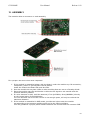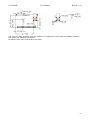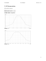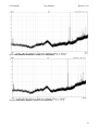
1
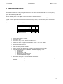
G3P-HAMP User Manual Release 1.02 G3P-HAMP User Manual Release. 1.02 1 G3P-HAMP User Manual Release 1.02 INDEX 1. RELEASE HISTORY ............................................................................................................ 3 1.1. Release 1.01 ......................................................................................................... 3 1.2. Release 1.02 ......................................................................................................... 3 2. GENERAL FEATURES .......................................................................................................... 4 3. CONTROL SIGNALS ........................................................................................................... 5 3.1. Control signals with external microcontroller .............................................................. 5 3.2. Control signals without an external microcontroller...................................................... 7 4. ORDER CODES ................................................................................................................. 7 5. AMP NETWORK ................................................................................................................. 8 5.1. General features ................................................................................................... 8 5.2. Working conditions ................................................................................................ 8 5.3. Address specifications ............................................................................................ 8 5.3.1 Address enumeration example .............................................................................. 9 5.3.2. Over mesh routing ............................................................................................ 10 5.3.3. Over mesh alternatives ...................................................................................... 10 5.4. AMP vs competition.............................................................................................. 10 5.4.1. Competition 868MHz routing............................................................................... 10 5.4.2. AMP routing ..................................................................................................... 11 6. TRANSMISSION features .................................................................................................. 12 6.1. SINGLE CHANNEL and DUAL CHANNELS transmission ................................................ 12 6.2. Hardware Sleep mode .......................................................................................... 12 6.3. MODULE TEST..................................................................................................... 12 7. PROGRAM MODE and RUN MODE ....................................................................................... 13 7.1. Program mode. ................................................................................................... 13 8. AMP COMMANDS ............................................................................................................. 13 8.1. Commands table. ................................................................................................ 13 8.2. Commands description. ........................................................................................ 14 9. AMP USE EXAMPLES ........................................................................................................ 18 9.1. AMP use with external microcontrollers ................................................................... 18 9.1.1. AMP network configuration .................................................................................. 19 9.1.2. Message transmission......................................................................................... 20 9.2. AMP use with stand alone slaves. ........................................................................... 21 9.2.1. AMP network configuration .................................................................................. 21 9.2.2. Remote command transmission............................................................................ 23 9.3. Add / remove slaves. ........................................................................................... 25 9.3.1. Add a device ..................................................................................................... 25 9.3.2. Remove a device ............................................................................................... 25 10. RADIO CHANNELS ........................................................................................................... 26 11. HARDWARE CONNECTIONS............................................................................................... 27 11.1. AMP with external microcontroller .......................................................................... 27 11.2. AMP stand alone.................................................................................................. 28 12. ASSEMBLY ..................................................................................................................... 29 12.1. Connector assembly............................................................................................. 30 12.2. Smd assembly .................................................................................................... 30 13. RF Harmonization ............................................................................................................ 32 2 G3P-HAMP User Manual Release 1.02 1. RELEASE HISTORY 1.1. Release 1.01 First release. 1.2. Release 1.02 Added commands C80 and C85. 3 G3P-HAMP User Manual Release 1.02 2. GENERAL FEATURES The G3P RF modules are a fully integrated transceiver for radio communications for the low frequency (433, 868 or 915MHz ISM band). Gp3 modules can implement different network architectures. Models available differ by the MCU on board and by the software features. Those modules provide a competitive solution for cost sensitive or for power critical applications. Typical wireless applications for these modules are security system, remote control, home automation… Operating at 3.3 V CMOS power supply, G3P modules have an asynchronous serial interface. Power Supply 2.2-3.6 V Supply current active mode @3V Supply current sleep mode @3V RF maximum power RF sensibility 15,35 3 10 -100 mA uA dBm dBm Temperature range -40 +75 °C The main AMP communication features include: 65536 networks. 65536 elements per network. Automatic AKN Automatic retry in case of communication error. Single channel or multi channel operating. Noise filter allows a proper communication even in very noisy fields. Simple serial interface commands. Enhanced mesh functions. AES 128 bit encryption available Multi master operation. Slave modules can operate with or without an external microcontroller. Special functions and I/O available for an efficient lighting control. o Two outputs o Two inputs. o Analog input 10 bit. o SPI output 8/16 bit MSB-LSB. o Programmable PWM output. o Set up trough radio remote commands. Broadcast messages or commands with AKN control. CE marked and homologated with a wire antenna 17cm long for 433MHz and 8cm long for 868MHz. Improved anti noise digital filter. 4 G3P-HAMP User Manual Release 1.02 3. CONTROL SIGNALS 3.1. Control signals with external microcontroller Pin 1 2 3 4 5 6 7 8 9 10 11 12 13 14 15 16 Function Function Alternative I/O I/O With ext. micro Stand alone Function Digital GND Digital Vcc Reset I I Rx I Reserved pull down I Tx O Program/run LED O Busy O PWM status O SPI *CE Reserved O PWM O Data Ready O Output #1 O SPI Clock Active O Output #2 O SPI Data Baud 0 I Input #1 I Baud 1 I Input #2 I *Data out Enable I Program/run push button I Sleep I Analog input I Reserved Reserved Radio GND Radio Vcc Note: Reserved pin #14 must left unconnected. Reserved pin #7 with an external microcontroller must be unconnected. Connect to GND all not used input pins. The module can be connected in SMD mode or trough the 2.54mm male strip See order codes. In the G3P hardware configuration the digital and radio supply are separated, and for best performances must be connected together in the power supply origin point. The Vcc range is from 2V to 3,6V. Rx and Tx signal are Cmos level and operating in asynchronous mode 8N1. *Reset Input pin, is the active low module reset. The module parameters are set to default Rx Asynchronous serial RX input at 3V. Tx Asynchronous serial TX output at 3V. Busy Output pin. Active high busy signal means that the module is processing the last command. Wait this signal to zero before load a command. Data Ready Active high output, means that the module has received data. The transmission of data on the RX pin depends by the state of “*Data enable Pin”. Active Output pin that shows the module status. High the module is active, low the module is sleeping. When wake up the module trough the SLEEP pin, wait this signal high before send commands. 5 G3P-HAMP Baud 0 Baud 1 Input baud rate selection: User Manual Release 1.02 Baud 0 Baud 1 Baud Rate GND GND 2400 GND VCC 4800 VCC GND 9600 VCC VCC 19200 Data out enable Active low input pin. Enables the TX pin to transmit the received data. Used with Data Ready pin, allows to wake up the user micro controller when a message is received. When the microcontroller wakes up and is ready, set low “*Data Out Enable” pin to it receive data on the serial interface. Sleep High active input pin. Put the module in the SLEEP HW mode. The module wakes up setting this pin low. 6 G3P-HAMP User Manual Release 1.02 3.2. Control signals without an external microcontroller *Reset Input pin, is the active low module reset. The module parameters are set to default Program / Run LED Output pin for an external led active low. Normal Status Rx radio data Run MODE Program MODE OFF ON FLASH *FLASH PWM Status / SPI *CE Output pin, indicates the PWM status. High: PWM >=1%. LOW: PWM = 0%. If enabled the alternative functions SPI *CE, will acts as active low CE for SPI. PWM Output pin, is the PWM output. PWM frequency can be set from 100Hz up to 1000Hz with steps of 100Hz. PWM duty can be set from 1% up to 99% with steps of 1%. OUPUT #1 / SPI CLOCK Output pin, is output #1 set or reset with radio commands. If enabled SPI, acts as SPI CLOCK, data valid on rising edge. OUPUT #2 / SPI DATA Output pin, is output #2 set or reset with radio commands. If enabled SPI, acts as SPI DATA. Data is valid at rising edge of SPI CLOCK. Output data is MSB-LSB. INPUT #1 Input pin, is input #1 read with a radio command. INPUT #2 Input pin, is input #2 read with a radio command. PROGRAM / RUN PUSH BUTTON Input pin. Connect an external push button to GND. Toggle the module in PROGRAM MODE and in RUN MODE. ANALOG INPUT 10 bit S&H analog input, read with a radio command. 4. ORDER CODES Code G3P-HAMP-433 G3P-HAMP-433-S G3P-HAMP-868 G3P-HAMP-868-S 433 433 868 868 Band Antenna Connection MHz 50 Ohm Strip MHz 50 Ohm Smd MHz / 915 MHz 50 Ohm Strip MHz / 915 MHz 50 Ohm Smd 7 G3P-HAMP User Manual Release 1.02 5. AMP NETWORK 5.1. General features AMP is a special routing stack born for Lighting control or big building network. It‟s a master–slave system, where the master asks and the slave answers. The multi-master performances allow having up to 10 different masters in the network. An UNLIMITED number of mesh allows realizing very big networks. A high performances routing allows a proper communication even in case of many slaves not working. No specific functions must be preview for mesh, like router or end points in other competition protocols. All the elements of the network are simply SLAVES; the mesh routing is completely dynamic. The Master elements must have an external microcontroller connected. The Slave elements can operate either with an external microcontroller connecter, that stand alone. No preview network entry element, every master can connect dynamically trough every slave. This allows working even if the preferred entry element is not working. Every master has 4 preferred network entry points. Broadcast messages or commands are controlled with AKN for every involved element. The goal of AMP is to connect a very large number of elements with a very little messages and rate required. 5.2. Working conditions AMP to work properly requires some specifics conditions: The master asks and the slave answers. A slave NEVER will start a communication if not expected by the master. All the slave elements must be powered all time. The master elements can sleep using the SLEEP pin. The addresses attribution must follows a specific preview system, see Address specifications chapter. Address or radio parameters change can be realized trough remote radio commands, without a local action required. In the radio rage of a single element, (350mt-500mt open air) must be reachable at least other 3 or more slaves. 5.3. Address specifications The AMP (Arianna‟s Mesh Protocol) has some specific address rules. The addresses are set by the customer using serial commands or remote radio commands. There are two address types: Network address that is the same for all the elements. This address identify a specific network, generally is different for every network. Device address is the address of an element inside the network and is different for every device. This address identifies the physical position into the network. A master must have only ONE device address in the range 0-9, up to 10 masters per network. The slaves must have at least ONE device address in the range 10-32767. The slaves can also have up to 4 device addresses, all in the range 10-32767 The slave‟s enumeration must start from 10 and then will increase without number holes. 8 G3P-HAMP 5.3.1 User Manual Release 1.02 Address enumeration example The AMP protocol is tough for linear network like street lights. In the reality street light have some lateral sub lines, for big building the main line is the floor to floor line and the laterals ones are the corridors. In this example we have 34 slave devices, they will have address from 10 up to 67. In a single line network the addresses will be from 10 to 44, but the lateral connections will increase the total addresses. Some device will have 1 address, other 2 and some 3. Starting from the starting one with address 10, go on and increase by 1 the address at each device. When will be founded a lateral sub net, follow that and go back. In the picture the way to follow for set addresses. Give sequentially the addresses and will be obtained: Now set to every device the 1, 2 or 3 addresses founded. 9 G3P-HAMP 5.3.2. User Manual Release 1.02 Over mesh routing The over mesh is based on the concept of step. The step is the long jump of the data among the devices. For example a step value of 10 means that the data will directly jump from address 10 to 20…30…the final jump will be reduced to reach the final destination. 5.3.3. Over mesh alternatives In case a device is not working, for example #20, the routing will have 9 alternative ways (equal step-1) to follow the data to the next jump. The next jump also will have other 9 alternatives. Longer is the way to reach the destination, more will be the mesh alternatives. In a linear network of 100 elements (addresses from 10 up to 110) the routing to reach the device #105 (10 normal jumps.)will be like: From 10 (the entry network point) to 110 Master ->10->20->30->40->50->60->70->80->90->100->105 The answer from 105 to 10 105->95->85->75->65->55->45->35->25->15->10->Master In this communication example the total amount of routing ways will be: ((Step-1)*total full step jumps)+last step In this routing the total amount of routing ways is 86. 5.4. AMP vs competition This sub chapter will compare the AMP routing features with the actual standard protocols on the market. All the competitors are based on the same concept of a structured network. Can be at 2.4GHz like Zig Bee or 868MHz proprietary, but the structure idea is the same: One COORDINATOR is the network fix entry point. Many ROUTERS allow the mesh (only routers can be realize the mesh) every protocol have a maximum mesh number limited. END DEVICES communicate with the COORDINATOR or with a ROUTER but cannot realize a mesh. The over mesh is obtained installing in one radio range at least 2 or 3 routers. If more then 2 or 3 subsequent routers are fault, the chain will be broken. The routing alternatives per jump are only 2 or 3. We take as example a linear network of 50 devices and compare between AMP and a structured protocol working at 868MHz, with the same RF band, power and propagation. In this comparison the use the distance between devices as 25mt, quite a standard in street lights. For both protocols we assume a valid radio range of 200mt. 5.4.1. Competition 868MHz routing A router every 100mt. Over mesh realized with a router in the middle. 3 end devices between a router and another one. A mesh every 4 devices. The structure will be like: C -> E -> E -> E ->R -> E -> E -> E -> R……… To communicate to device #50 the routing results are: 7 mesh jumps Globally 13 different routing ways Maximum router fault =1. 10 G3P-HAMP 5.4.2. User Manual Release 1.02 AMP routing The structure will be like: Step=8 (200/25=8). device -> device -> device -> device -> device ……… No pre fixed network entry point. To communicate to device #50 the routing results are: 7 mesh jumps Globally 48 different routing ways Maximum device fault =7. Compare conditions: Frequency Radio range Radio power Device distance 868MHz 200mt 10mW 25mt Maximum mesh number Maximum chain Master number Router position fixed in advance Mesh routing Jumps to reach device #100 Global routing ways to reach device #100 Subsequent critical fault Note: *1 *2 Standard System Coordinator, Router, End point 10/15 *1 40/60 elements *2 1 YES Fixed in advance 14/27 *2 26 1/2 *2 AMP System Unlimited 32757 elements 10 NO Dynamic 14 107 7 Depends by product. Depends by protocol. 11 G3P-HAMP User Manual Release 1.02 6. TRANSMISSION features All the devices have two kinds of addresses. Network address must be the same for all devices in the network. This allows to have different networks separated but in the same radio range. Device address indentifies the device inside the network. See chapter Address specifications. 6.1. SINGLE CHANNEL and DUAL CHANNELS transmission The communication can be set in single channel or in frequency hopping mode. In the single channel mode the user chooses the frequency channel of the communication. There are 17 available channels for transmission in 433 MHz ISM band, 5 for transmission in 868 MHz ISM band and 65 channels in 915MHz band. In Dual Channels mode, the modules will use two channels at time. This slow a little the transmission time but increase very much the anti noise features. Setting this mode, specify two not near channels. This feature is better in 433Mhz frequency due to the law duty cycle. In 433MHz band the allowed duty cycle is 10%, otherwise using the dual channels mode in 868MHz band will limit the duty cycle to 0,1%. 6.2. Hardware Sleep mode Hardware sleep mode can be used only in the MASTER devices. The SLAVE devices must be active all time. Setting HIGH the SLEEP input (PIN 13) the device enters in hardware power done mode. The module completes all the pending transmission before entering in this power down mode. The device wakes up only by setting low PIN 13. During the Power down mode radio and serial interface aren‟t available and the power consumption drops down to 3 µA. 6.3. MODULE TEST To test the first time the G3P module, connect to a PC or to a microcontroller. Use the C54 command to verify if the module is working. C54 The module answers model and firmware release. Ex: G3P-HAMP-868 R101 12 G3P-HAMP User Manual Release 1.02 7. PROGRAM MODE and RUN MODE The AMP module has two different status, PROGRAM mode and RUN mode. Run mode is the normal communication status. In program mode are accepted serial commands or radio commands to set the module or the radio parameters. 7.1. Program mode. To enter in program mode send the command C121 if an external micro is connected. If the module is working stand alone, push the button connected to pin #12. The led connected to pin #5 will switch on to indicate the programming mode status. In this status the module will use addresses and radio channel reserved. This allows to radio set a slave from a master without loose the radio link. The set up command will be ignored if the module is not in programming mode. To exit from program mode send the command C120 if an external micro is connected. If the module is working stand alone, push again the button connected to pin #12. The led connected to pin #5 will switch off to indicate the running mode status. 8. AMP COMMANDS The commands syntax is case sensitive and needs to strictly respect the syntax. No extra characters are allowed. There are 4 different conditions to use a command. Command condition: S SP R RP Command Command Command Command available available available available from serial connection in RUN mode. from serial connection in PROGRAM mode as radio command if the target module is in RUN mode. as radio command if the target module is in PROGRAMMING mode. 8.1. Commands table. Type Set up Master Radio Master Condition SP,RP SP,RP SP,RP SP,RP SP,RP S,SP S,SP S,SP S,SP SP,RP SP,RP S,SP RP RP Command C00 C01 C02 C03 C04 C05 C06 C07 C08 C10 C11 C12 C13 C14 Parameters nnnnn nnnnn nnnnn nnnnn nnnnn nnnnn nnnnn nnnnn nnnnn aabb n n faaann adcnnnnn Description Load Network Address Load Device address #1 Load Device address #2 Load Device address #3 Load Device address #4 Load Master bridge address Load Master bridge address Load Master bridge address Load Master bridge address Set radio channels Set Tx power Set / Reset program mode Set PWM parameters Set SPI parameters S,SP S,SP C16 C17 nn n Set communication step Set/reset broadcast mode Use in master module n=1 broadcast enabled, n=0 broadcast disable R R R R R C20 C21 C22 C23 C24 nn ns nnnnn Set PWM to nn Set/reset out #n Out SPI data Slave I/O read Device address subsitution nn=00-99, 00=stop PWM s=0 reset, s=1 set SPI 8 bit 00000-00255, SPI 16 bit 00000-65535 Send to master I/O and AD values nnnnn replaces the receiving address S S SP S S,SP S,SP C30 C31 C32 C45 C80 C85 nnnnndd..CR nnnnnCxx(data)CR Cxx(data)CR Tx to nnnnn message dd…CR Tx to nnnnn command Cxx..CR Tx R type setup command Store set up Generate fixed carrier Send back an „*‟ CR ends the message, max len 15 bytes Remote command to slave, CR ends. CR ends command nnnnn n #1 #2 #3 #4 Note nnnnn from 00001 to 65535 Master 00000-00009 Slave 00010-32767 Slave 00010-32767 Slave 00010-32767 Slave 00010-32767 nnnnn from 00010 to 32767 nnnnn from 00010 to 32767 nnnnn from 00010 to 32767 nnnnn from 00010 to 32767 if bb=00 mono channel aa, else dual channels aa and bb n=3 +10dBm, n=2 +6dBm, n=1 -2dBm, n=0 -10dBm n=1 program mode, n=0 run mode f=freq, aaa=acceleration, nn=starting percentage a=abilitation, d=8/16 bit,nnnnn=starting out data n=1 carrier on, n=0 carrier off 13 G3P-HAMP User Manual Release 1.02 8.2. Commands description. Operating conditions: S Serial command in run mode. SP Serial command in program mode (after command C121). R Radio command sent by the master using C31 and received in run mode. RP Radio command sent by the master using C32 and receives in program mode(after pushbutton pressed). <CR> Carriage return character, ASCII code 13 decimal, 0D Hex. Parameters Description Operating conditions C00 nnnnn Set NETWORK address Set the network address, nnnnn is an ASCII decimal number in the range 00001-65535. This command is available both in a master module and in a slave one too. SP,RP C01 nnnnn Set the device address #1, nnnnn Master module: Slave module with ext micro: Slave module stand alone: Set DEVICE address #1 is an ASCII decimal number. nnnnn is in the range 00000-00009. nnnnn is in the range 00010-32767. Sent by the master using radio command C32. SP,RP C02 nnnnn Set DEVICE address #2 It‟s an optional command for a slave module. Add the device address #2, nnnnn is an ASCII decimal number. Use this command after C01, now the slave module has 2 device addresses. Slave module with ext micro: nnnnn is in the range 00010-32767. Slave module stand alone: Sent by the master using radio command C32. SP,RP C03 nnnnn Set DEVICE address #3 It‟s an optional command for a slave module. Add the device address #3, nnnnn is an ASCII decimal number. Use this command after C01, C02. Now the slave module has 3 device addresses. Slave module with ext micro: nnnnn is in the range 00010-32767. Slave module stand alone: Sent by the master using radio command C32. SP,RP C04 nnnnn Set DEVICE address #4 It‟s an optional command for a slave module. Add the device address #4, nnnnn is an ASCII decimal number. Use this command after C01, C02, C03. Now the slave module has 4 device addresses. Slave module with ext micro: nnnnn is in the range 00010-32767. Slave module stand alone: Sent by the master using radio command C32. SP,RP C05 nnnnn Set BRIDGE address #1 S,P This command can be used ONLY in a master module. The BRIDGE address #1 is the first address that the master will use to transmit into the network. nnnnn is an ASCII decimal number and is the device address of a slave device. C06 nnnnn Set BRIDGE address #2 S,P This command can be used ONLY in a master module. The BRIDGE address #2 is the second address that the master will use to transmit into the network in case of bridge address #1 fails. nnnnn is an ASCII decimal number and is the device address of a slave device. Use this command after C05. Now the master module has 2 bridge addresses. C07 nnnnn Set BRIDGE address #3 S,P This command can be used ONLY in a master module. The BRIDGE address #3 is the third address that the master will use to transmit into the network in case of bridge address #1 and #2 fail. nnnnn is an ASCII decimal number and is the device address of a slave device. Use this command after C05, C06. Now the master module has 3 bridge addresses. C08 nnnnn Set BRIDGE address #4 S,P This command can be used ONLY in a master module. The BRIDGE address #4 is the fourth address that the master will use to transmit into the network in case of bridge address #1 , #2 and #3 fail. nnnnn is an ASCII decimal number and is the device address of a slave device. Use this command after C05, C06, C07. Now the master module has 4 bridge addresses. 14 G3P-HAMP User Manual Parameters Description Release 1.02 Operating conditions C10 aabb Set radio channels Set the radio channels to use and also defines if work in single or dual channel mode. Parameter aa: First radio channel to use. Parameter bb If =00 set the single channel mode, channel used will be aa. If >00 set the dual channel mode, the used channels will be aa and bb. See the chapter Radio Channels for specifications. SP,RP C11 n Set the radio power Parameter n: 0: 1: 2: 3: SP,RP Set radio Tx power in transmission. ASCII decimal number in the range 0-3. -10dBm (1mW). -2dBm (1.58mW). +6dBm (3.98mW). +10dBm (10mW). C12 n Set/Reset program mode Set the module in program mode or in run mode. Parameter n: ASCII decimal number in the range 0-1. 0: Set run mode. 1: Set program mode. S,SP C13 faaann Set PWM parameters RP This command can be sent to a stand alone slave in program mode, to set the PWM operating parameters. The master in program mode will use the command C32 to send the C13 remote command. Parameter f: ASCII decimal number in the range 0-1. Set the PWM frequency. 1: 100Hz. 2: 200Hz. 3: 300Hz. 4: 400Hz. 5: 500Hz. 6: 600Hz. 7: 700Hz. 8: 800Hz. 9: 900Hz. 0: 1000Hz. Parameter aaa: ASCII decimal number in the range 000-255. Set the PWM acceleration time. This is the time to switch from PWM 0% to 99%. Parameter nn: PWM different changes will apply a proportional time to generate a constant in the external power supply. 000: Acceleration off. abc: Acceleration ab.c seconds. 255 Acceleration 25.5 seconds. ASCII decimal number in the range 00-99. Set the PWM value to use at power on. v/t C14 adcnnnnn Set SPI parameters RP This command can be sent to a stand alone slave in program mode, to set the SPI operating parameters. The master in program mode will use the command C32 to send the C14 remote command. Parameter a: ASCII decimal number in the range 0-1. 0: SPI not used, OUT#1, OUT#2, PWM status available. 1: SPI enabled, OUT #1, OUT #2 not available. Parameter d: ASCII decimal number in the range 0-1. 0: SPI 8 bit mode. 1: SPI 16 bit mode. Parameter c: ASCII decimal number in the range 0-1. 0: SPI *CE not used, PWM status available, OUT #1, OUT #2 not available. 1: SPI *CE enabled, OUT#1, OUT#2, PWM status available. Parameter nnnnn: ASCII decimal number in the range 00000-nnnnn. Set the SPI value to output at power on. In 8 bit mode (parameter c=0) nnnnn range 00000-00255. In 16 bit mode (parameter c=1) nnnnn range 00000-65535. C16 nn Set communication step This command can be used only in a master device. Set the communication step (long jump), unit is the number of slave device to jump. Step can be changed in every moment before a communication. Parameter nn: ASCII decimal number in the range 00-99. S,SP 15 G3P-HAMP Parameters User Manual Description Release 1.02 Operating conditions C17 n Set/Reset broadcast mode S,SP This command can be used only in a master device. Set or reset the broadcast mode for messages or remote commands. Broadcast mode can be changed in every moment before a communication. Parameter n: ASCII decimal number in the range 0-1. 0: Broadcast mode disabled. Data will reach only the final destination module. 1: Broadcast mode enabled. Data will reach the final destination module and all modules in the address range between the final one and the bridge used. C20 nn Set PWM value This command can be sent to a stand alone slave in run mode, to set the PWM value. The master will use the command C31 to send the C20 remote command. Parameter nn: ASCII decimal number in the range 00-99. 00=PWM stop, 01-99 new PWM value. R C21 ns Set/Reset remote output This command can be sent to a stand alone slave in run mode, to set a remote output. The master will use the command C31 to send the C21 remote command. Parameter n: ASCII decimal number in the range 1-2. Output number to set or reset. Parameter s: ASCII decimal number in the range 0-1. 0: Reset the output n. 1: Set the output n. R C22 nnnnn Output SPI data This command can be sent to a stand alone slave in run mode, to set a remote output. The master will use the command C31 to send the C22 remote command. Parameter nnnnn: ASCII decimal number. SPI 8 bit mode: nnnnn in the range 00000-00255. SPI 16 bit mode: nnnnn in the range 00000-65535. R C23 Read remote I/O R This command can be sent to a stand alone slave in run mode, to read I/O. The master will use the command C31 to send the C23 remote command. After received the slave will transmit the I/O values in the format I1s,I2s,O1s,O2s,nnnn,pp<CR>. I1s Input #1, s=0/1. I2s Input #2, s=0/1. O1s Output #1, s=0/1. O2s Output #2, s=0/1. nnnn Analog input value, nnnn in the range 0000-1023. pp PWM value, pp in the range 00-99. C24 nnnnn Remote address substitution This command can be sent to a stand alone slave in run mode, to read I/O. The master will use the command C31 to send the C24 remote command. Useful to change one of the device addresses in case of network reconfiguration. The slave will substitute the address active with the new one. Parameter nnnnn: ASCII decimal number in the range 00010-32767. R C30 nnnnn(message)<CR> Tx a massage to a slave This command can be used only in a master device in run mode. Send a message to a slave with an external microcontroller. Parameter nnnnn: ASCII decimal number in the range 00010-32767. Address of the slave. Parameter (message): message to send, max 15 characters, terminated by a <CR>. S C31 nnnnnCxx(par)<CR> Tx a remote command to a slave This command can be used only in a master device in run mode. Send a message to a stand alone slave. Parameter nnnnn: ASCII decimal number in the range 00010-32767. Address of the slave. Parameter Cxx(par): Command and parameters to send, terminated by a <CR>. S C32 Cxx(par)<CR> Tx a remote setup command to a slave This command can be used only in a master device in program mode. Send a remote setup command to a stand alone slave in program mode. Parameter Cxx(par): Command and parameters to send, terminated by a <CR>. SP 16 G3P-HAMP Parameters User Manual Description Release 1.02 Operating conditions C45 Store setup in flash S This command can be used only in a device with an external microcontroller and in run mode. Store the setup in flash to use at the next power up. In a slave device stand alone, this action is automatically done at the exit from program mode (led off). 17 G3P-HAMP User Manual Release 1.02 9. AMP USE EXAMPLES The AMP protocol use is very easy. The system has: Up to 10 master devices with an external microcontroller connected. Up to 32757 slave devices that can operate either stand alone or with an external microcontroller. A master begins a communication sending a message or a remote command to a slave. A slave devices transmit to a master only after receiving data from the master. For maintenance simplicity, the stand alone slaves can remotely setup. The system can have up to 10 masters, but its better activate one master per time. A master can communicate using every slave as network bridge, this allows for example to stop the main master, use a portable master for tests or maintenance works along the line. The devices have two operating modes, programming mode and run mode. Programming mode allows only the setup commands, while run mode allows only communication commands. In the examples we‟ll assume a network like: One master with address 00000. 19 slaves with some lateral sub networks. (see picture). Master will use 4 entry points: 10,11,12,18. Dual channel mode using channels #04 and #14. Communication step=5. The examples with external microcontrollers show: Messages transmissions. Correct transmissions. Recovered error transmissions. Unrecovered error transmissions. The examples with stand alone modules show: PWM , SPI, I/O remote commands. Correct transmissions. Broadcast transmissions. The errors recovery is the same in both cases. The broadcast transmission is the same in both cases. 9.1. AMP use with external microcontrollers Both masters and slaves operate with an external microcontroller. In this case AMP will route messages so all functions and remote commands concerning PWM, SPI, I/O will not be available. 18 G3P-HAMP 9.1.1. User Manual Release 1.02 AMP network configuration With an external microcontroller, every module will be configured by its own microcontroller. Initialization differs between masters and slaves. 9.1.1.1. Master configuration In the description field, commands and parameters are separated by “,”. This is to be clearer; the real command to send is without commas, like in the first field. Send to the master C121 C0012345 C010000 C0500010 C0600011 C0700012 C0800018 C100414 C113 C1605 C170 C120 C45 9.1.1.2. the serial commands: C12,1 set program mode C00,12345 set network address to 12345. C01,00000 set device address to 00000; Master bus have address <00010. C05,00010 set first using bridge to 00010. C06,00011 set second using bridge to 00011. C07,00012 set third using bridge to 00012. C08,00018 set fourth using bridge to 00018. C10,0414 set dual channel mode with channels #04 and #14. C11,3 set tx power 10mW C16,05 set step=5. C17,0 set broadcast mode disabled. C12,0 exit from programming mode. C45 stores setup in flash. Slaves configuration Send to the slave #00010 (1 device address) the serial commands: C121 C12,1 set program mode C0012345 C00,12345 set network address to 12345. C010010 C01,00010 set device address #1 to 00010. C100414 C10,0414 set dual channel mode with channels #04 and #14. C113 C11,3 set tx power 10mW C120 C12,0 exit from programming mode. C45 C45 stores setup in flash. Send to the slave #00013 (2 device addresses) the serial commands: C121 C12,1 set program mode C0012345 C00,12345 set network address to 12345. C010013 C01,00013 set device address #1 to 00013. C020037 C02,00037 set device address #2 to 00037. C100414 C10,0414 set dual channel mode with channels #04 and #14. C113 C11,3 set tx power 10mW C120 C12,0 exit from programming mode. C45 C45 stores setup in flash. Send to the slave #00016 (3 device addresses) the serial commands: C121 C12,1 set program mode C0012345 C00,12345 set network address to 12345. C010016 C01,00016 set device address #1 to 00016. C020020 C02,00020 set device address #2 to 00020. C030034 C03,00034 set device address #3 to 00034. C100414 C10,0414 set dual channel mode with channels #04 and #14. C113 C11,3 set tx power 10mW C120 C12,0 exit from programming mode. C45 C45 stores setup in flash. For other slaves the set up is the same, will change only addresses. 19 G3P-HAMP 9.1.2. User Manual Release 1.02 Message transmission When the master start a transmission, will use bridge #10. If bridge #10 fails, automatically will try with bridges #11, #12 and #18 in order. After the transmission gives the result as: OK, address bridge used, number of recovered errors. 1. OK,00010,000 Used bridge #10, no errors. 2. OK,00011,001 Bridge #10 failed, used #11, 1 total error (#10 fail). ER, address last bridge used, number of errors, 1. ER,00018,004 All 4 bridges failed, last used was #18, the message has not delivered. If successful means only that the message has been properly posted into the network. In case the routing will not deliver the message, later the master will receive a notification like: KO, nnnnn, eee The slave nnnnn has not received data, eee=number of total errors. After the routing has finished: 1. AK,nnnnn,000 Message delivered to slave nnnnn, with 000 errors. The destination slave will send on its own serial port: nnnnn,eee,message<CR> Data from master nnnnn, eee recovered errors in the routing, message sent. 9.1.2.1. Transmission to slave #26 successful. Master command Action Master serial C3000026Stupid<CR> Send to #26 message “Stupid” Tx trough the bridge #10 #26 serial OK,00010,000 Routing to #26 00000,000,Stupid AK,00026,000 9.1.2.2. Transmission to slave #26, bridge #10 fault. Master command Action Master serial C3000026Stupid<CR> Send to #26 message “Stupid” Tx trough the bridge #10 #10 fails, try with #11 #26 serial OK,00011,001 Routing to #26 00000,001,Stupid AK,00026,000 9.1.2.3. Transmission to slave #26, #26 off line Master command Action Master serial C3000026Stupid<CR> Send to #26 message “Stupid” Tx trough the bridge #10 #26 serial OK,00010,000 Routing to #26 #26 fails 9.1.2.4. KO,00026,001 Transmission to slave #26, #16 and #24 fault Master command Action Master serial C3000026Stupid<CR> Send to #26 message “Stupid” Tx trough the bridge #10 #26 serial OK,00010,000 Routing Routing Routing Routing Routing Routing to#15 OK (errors=0) to #20 fails. (errors=1) to #19 OK (errors=1) to #24 fails (errors=2) to #23 OK (errors=2) to #26 OK (errors=2) 0000,002,Stupid AK,00026,002 20 G3P-HAMP User Manual 9.1.2.5. Release 1.02 Transmission to slave #26, #16 and #24 fault, #26 answers Master command Action Master serial C3000026Stupid<CR> Send to #26 message “Stupid” Tx trough the bridge #10 #26 serial OK,00010,000 Routing Routing Routing Routing Routing Routing to#15 OK (errors=0) to #20 fails. (errors=1) to #19 OK (errors=1) to #24 fails (errors=2) to #23 OK (errors=2) to #26 OK (errors=2) 0000,002,Stupid AK,00026,002 Routing Routing Routing Routing Routing 9.1.2.6. to to to to to C300000You too<CR> #21 OK (errors=2) #16 fails (errors=3) #17 OK (errors=3) #12 OK (errors=3) Bridge #10 OK (errors=3) 00026,003,You too<CR> Transmission to slave #26, #16 to #24 fault, network broken Master command Action C3000026Stupid<CR> Send to #26 message “Stupid” Tx trough the bridge #10 Master serial #26 serial OK,00010,000 Routing to#15 OK (errors=0) Routing to #20 fails. (errors=1) Routing to #19 fails (errors=2) Routing to #18 fails (errors=3) Routing to #17 fails (errors=4) Routing to #16 fails (errors=5) Slave #15 generate error back to master ER,00016,005 9.2. AMP use with stand alone slaves. Master operates with an external microcontroller. Slaves are stand alone, all functions and remote commands concerning PWM, SPI, I/O are available. 9.2.1. AMP network configuration The master will be initialized by serial commands. The slaves will be initialized by radio commands sent by the master. There is not a preview sequence, master can be initialized before or after slaves. The remote radio slaves setup commands, will not use the master network setup. The slave setup trough radio commands is a direct radio communication between the master and the slave. The master MUST be on the radio range of the slave to initialize. In case the master is physically too far, use another portable master. 21 G3P-HAMP 9.2.1.1. User Manual Release 1.02 Master configuration In the description field, commands and parameters are separated by “,”. This is to be clearer; the real command to send is without commas, like in the first field. Send to the master the serial commands: C121 C0012345 C010000 C0500010 C0600011 C0700012 C0800018 C100414 C113 C1605 C170 C120 C45 9.2.1.2. C12,1 set program mode C00,12345 set network address to 12345. C01,00000 set device address to 00000; Master bus have address <00010. C05,00010 set first using bridge to 00010. C06,00011 set second using bridge to 00011. C07,00012 set third using bridge to 00012. C08,00018 set fourth using bridge to 00018. C10,0414 set dual channel mode with channels #04 and #14. C11,3 set tx power 10mW C16,05 set step=5. C17,0 set broadcast mode disabled. C12,0 exit from programming mode. C45 stores setup in flash. Slaves configuration Initialize slave #00010 (1 device address). Master command C121 C32C001234<CR> C32C010010<CR> C32C100414<CR> C32C113<CR> C32C13112500<CR> C32C1411100000<CR> C12,0 Action Press pushbutton on the slave, the led switch on. The slave is in program mode. Master in program mode. Set network address to 12345. Set device address #1 to 00010. Set dual channel mode with channels #04 and #14. Set tx power 10mW Set PWM 100Hz, 12.5 seconds for acceleration, initial value 00%. Set SPI enabled, 16 bit, *CE enabled, initial value 00000. Master exits from programming mode. Press again pushbutton on the slave, the led goes off. The slave exit from program mode and then store setup into the flash. Initialize slave #00013 (2 device addresses). Master command C121 C32C001234<CR> C32C010013<CR> C32C020037<CR> C32C100414<CR> C32C113<CR> C32C13112500<CR> C32C1411100000<CR> C12,0 Action Press pushbutton on the slave, the led switch on. The slave is in program mode. Master in program mode. Set network address to 12345. Set device address #1 to 00013. Set device address #2 to 00037. Set dual channel mode with channels #04 and #14. Set tx power 10mW Set PWM 100Hz, 12.5 seconds for acceleration, initial value 00%. Set SPI enabled, 16 bit, *CE enabled, initial value 00000. Master exits from programming mode. Press again pushbutton on the slave, the led goes off. The slave exit from program mode and then store setup into the flash. 22 G3P-HAMP User Manual Release 1.02 Initialize slave #00016 (3 device addresses). Master command Action C121 C32C001234<CR> C32C010016<CR> C32C020020<CR> C32C030034<CR> C32C100414<CR> C32C113<CR> C32C13112500<CR> C32C1411100000<CR> C12,0 Press pushbutton on the slave, the led switch on. The slave is in program mode. Master in program mode. Set network address to 12345. Set device address #1 to 00016. Set device address #2 to 00020. Set device address #3 to 00034. Set dual channel mode with channels #04 and #14. Set tx power 10mW Set PWM 100Hz, 12.5 seconds for acceleration, initial value 00%. Set SPI enabled, 16 bit, *CE enabled, initial value 00000. Master exits from programming mode. Press again pushbutton on the slave, the led goes off. The slave exit from program mode and then store setup into the flash. For other slaves the set up is the same, will change only addresses. 9.2.2. Remote command transmission When the master start a transmission, will use bridge #1. If bridge #1 fails, automatically will try with bridges #11, #12 and #18 in order. After the transmission gives the result as: OK, address bridge used, number of recovered errors. 1. OK,00010,000 Used bridge #10, no errors. 2. OK,00011,001 Bridge #10 failed, used #11, 1 total error (#10 fail). ER, address last bridge used, number of errors, 1. ER,00018,004 All 4 bridges failed, last used was #18, the message has not delivered. If successful means only that the message has been properly posted into the network. In case the routing will not deliver the message, later the master will receive a notification like: KO, nnnnn, eee The slave nnnnn has not received data, eee=number of total errors. After the routing has finished: 1. AK,nnnnn,000 Message delivered to slave nnnnn, with 000 errors. The destination slave will send on its own serial port: nnnnn,eee,message<CR> Data from master nnnnn, eee recovered errors in the routing, message sent. 9.2.2.1. PWM value slave #26. Master command Action C3100026C2033<CR> PWM of #26 =33% Tx trough the bridge #10 Master serial #26 OK,00010,000 Routing to #26 PWM to 33% AK,00026,000 9.2.2.2. SPI value slave #26. Master command Action C3100026C2232768<CR> Out 32768 from #26 SPI. Tx trough the bridge #10 Master serial #26 OK,00010,000 Routing to #26 SPI out 32768 AK,00026,000 23 G3P-HAMP 9.2.2.3. User Manual Release 1.02 I/O set slave #26. Master command Action C3100026C2110<CR> Reset out #1 of #26.(no outputs available if SPI enabled) Tx trough the bridge #10 Master serial #26 OK,00010,000 Routing to #26 Output #1=0 AK,00026,000 9.2.2.4. I/O read slave #26. Master command Action C3100026C23<CR> Read I/O of #26. Tx trough the bridge #10 Master serial #26 OK,00010,000 Routing to #26 AK,00026,000 Transmits back I/O Routing to Master. I10,I21,O10,O20,0325,32 Input #1=0, Input #2=1, Out #1=0, Out #2=0, AD=325, PWM=32% 9.2.2.5. PWM value to all in broadcast mode #1. Bridge=10, the bridge is the lower address. Can be obtained with one command. Set the higher address with broadcast mode activated. Master command Action C171 C3100026C2033<CR> Set broadcast mode. PWM up to #26 =33% Tx trough the bridge #10 Master serial #26 OK,00010,000 Routing to #26 and less #10 to #26, PWM=33% AK,00026,000 C170 Reset broadcast mode. 9.2.2.6. PWM value to all in broadcast mode #2. Bridge=18, the bridge is the middle of the network. Can be obtained with two separated commands. Set the higher address with broadcast mode activated. Set the lower address with broadcast mode activated. Master command Action C171 C3100026C2033<CR> Set broadcast mode. PWM up to #26 =33% Tx trough the bridge #18 Master serial #26 OK,00018,000 Routing to #26 and less #18 to #26, PWM=33% AK,00026,000 C3100010C2033<CR> PWM down to #10 =33% Tx trough the bridge #18 OK,00018,000 Routing to #10 and higher #18 to #10, PWM=33% AK,00018,000 C170 Reset broadcast mode. 24 G3P-HAMP User Manual Release 1.02 9.3. Add / remove slaves. In a just installed network, it‟s possible to add or remove slaves without local actions. Physically is necessary to remove or add the concerned slaves, the necessary changes in the address sequence can be made through radio commands. 9.3.1. Add a device To add the new device, the operations are: 1. 2. 3. 4. 5. Configure the new device in program mode. Install the new device in place. Switch off the new one (an address 14 just exist). Using the network change the slave addresses leaving free the address 14. Switch on the new one. In this case the higher address will increase of two units. Use a step double than the increase entity. Last device will change address from 16 to 18, so use step=4 or more. Start to increase the addresses from the last and proceed up the lower. Will be used the command C31 to send the remote command C24. Change address 16 to 18. Master command: C3100016C2400018<CR> The addresses sequence now is: 10, 11, 12, 13, Change address 15 to 17. Master command: C3100015C2400017<CR> The addresses sequence now is: 10, 11, 12, 13, Change address 14 to 16. Master command: C3100014C2400016<CR> The addresses sequence now is: 10, 11, 12, 13, Add address #2 15 to device 13. Master command: C3100013C0200015<CR> The addresses sequence now is: 10, 11, 12, 13, 14, 15, x, x, 18. 14, x, x, 17, 18. x, x, 16, 17, 18. x, 15, 16, 17, 18. Now switch on the new slave #14. 9.3.2. Remove a device To remove a device, the operations are: 1. Switch off the device to remove. 2. Using the network change the slave addresses. In this case the higher address will decrease of two units. Use a step double than the decrease entity. Last device will change address from 18 to 16, so use step=4 or more. Start to decrease the addresses from the first after the removed one and proceed up the last. Will be used the command C31 to send the remote command C24. Remove address #2 15 to device 13 (set to Master command: C3100013C0265535<CR> The addresses sequence now is: 10, 11, 12, 13, Change address 16 to 14. Master command: C3100016C2400014<CR> The addresses sequence now is: 10, 11, 12, 13, Change address 17 to 15. Master command: C3100017C2400015<CR> The addresses sequence now is: 10, 11, 12, 13, Change address 18 to 16. Master command: C3100018C2400016<CR> The addresses sequence now is: 10, 11, 12, 13, 65535). x, x, 16, 17, 18. 14, x, x, 17, 18. 14, 15, x, x, 18. 14, 15, 16, x, x. 25 G3P-HAMP User Manual Release 1.02 10. RADIO CHANNELS The following table shows the channels band for communication for 433 MHz Channel # 1 2 3 4 5 6 7 8 9 10 11 12 13 14 15 16 17 f min f0 f max Duty dBm 433,05 433,15 433,25 433,35 433,45 433,55 433,65 433,75 433,85 433,95 434,05 434,15 434,25 434,35 434,45 434,55 434,65 433,1 433,2 433,3 433,4 433,5 433,6 433,7 433,8 433,9 434 434,1 434,2 434,3 434,4 434,5 434,6 434,7 433,15 433,25 433,35 433,45 433,55 433,65 433,75 433,85 433,95 434,05 434,15 434,25 434,35 434,45 434,55 434,65 434,75 10% 10% 10% 10% 10% 10% 10% 10% 10% 10% 10% 10% 10% 10% 10% 10% 10% 10 10 10 10 10 10 10 10 10 10 10 10 10 10 10 10 10 The following table shows the channels band for communication for 868 MHz Channel # 1 2 3 4 5 f min f0 868,1 868,3 868,7 868,9 869,7 868,2 868,4 868,8 869 869,8 f max 868,3 868,5 868,9 869,1 869,9 Duty dBm 1% 1% 0,10% 0,10% 100% 10 10 10 10 6 The following table shows the channels band for communication for 915 MHz Channel # 1 2 3 4 5 6 7 8 9 10 11 12 13 14 15 16 17 18 19 20 21 22 23 24 25 26 27 28 29 30 31 32 33 f min 902,1 902,5 902,9 903,3 903,7 904,1 904,5 904,9 905,3 905,7 906,1 906,5 906,9 907,3 907,7 908,1 908,5 908,9 909,3 909,7 910,1 910,5 910,9 911,3 911,7 912,1 912,5 912,9 913,3 913,7 914,1 914,5 914,9 f0 902,2 902,6 903 903,4 903,8 904,2 904,6 905 905,4 905,8 906,2 906,6 907 907,4 907,8 908,2 908,6 909 909,4 909,8 910,2 910,6 911 911,4 911,8 912,2 912,6 913 913,4 913,8 914,2 914,6 915 f max 902,3 902,7 903,1 903,5 903,9 904,3 904,7 905,1 905,5 905,9 906,3 906,7 907,1 907,5 907,9 908,3 908,7 909,1 909,5 909,9 910,3 910,7 911,1 911,5 911,9 912,3 912,7 913,1 913,5 913,9 914,3 914,7 915,1 Duty 100% 100% 100% 100% 100% 100% 100% 100% 100% 100% 100% 100% 100% 100% 100% 100% 100% 100% 100% 100% 100% 100% 100% 100% 100% 100% 100% 100% 100% 100% 100% 100% 100% dBm 10 10 10 10 10 10 10 10 10 10 10 10 10 10 10 10 10 10 10 10 10 10 10 10 10 10 10 10 10 10 10 10 10 Channel # 34 35 36 37 38 39 40 41 42 43 44 45 46 47 48 49 50 51 52 53 54 55 56 57 58 59 60 61 62 63 64 65 f min 915,3 915,7 916,1 916,5 916,9 917,3 917,7 918,1 918,5 918,9 919,3 919,7 920,1 920,5 920,9 921,3 921,7 922,1 922,5 922,9 923,3 923,7 924,1 924,5 924,9 925,3 925,7 926,1 926,5 926,9 927,3 927,7 f0 915,4 915,8 916,2 916,6 917 917,4 917,8 918,2 918,6 919 919,4 919,8 920,2 920,6 921 921,4 921,8 922,2 922,6 923 923,4 923,8 924,2 924,6 925 925,4 925,8 926,2 926,6 927 927,4 927,8 f max 915,5 915,9 916,3 916,7 917,1 917,5 917,9 918,3 918,7 919,1 919,5 919,9 920,3 920,7 921,1 921,5 921,9 922,3 922,7 923,1 923,5 923,9 924,3 924,7 925,1 925,5 925,9 926,3 926,7 927,1 927,5 927,9 Duty 100% 100% 100% 100% 100% 100% 100% 100% 100% 100% 100% 100% 100% 100% 100% 100% 100% 100% 100% 100% 100% 100% 100% 100% 100% 100% 100% 100% 100% 100% 100% 100% dBm 10 10 10 10 10 10 10 10 10 10 10 10 10 10 10 10 10 10 10 10 10 10 10 10 10 10 10 10 10 10 10 10 26 G3P-HAMP User Manual Release 1.02 11. HARDWARE CONNECTIONS G3P modules can be connected in different ways, depending by the availability of I/O from the user microcontroller. 11.1. AMP with external microcontroller The master devices can use the sleep pin if required. Connection diagram for 19200 baud. If a different baud rate is required, change pin 10 and 11 polarization. Micro Controller 1 2 3 4 5 6 7 8 9 10 11 12 13 14 15 16 Digital GND Digital VCC *Reset Rx Tx Busy Baud 0 Baud 1 *Data Enable Sleep Reset G3P Output Serial Tx Serial Rx Busy Input uP VCC + 3.3V uP GND GND HW Sleep control Output Radio GND Radio VCC The slave devices cannot use the sleep. Connection diagram for 19200 baud. If a different baud rate is required, change pin 10 and 11 polarization. Micro Controller 1 2 3 4 5 6 7 8 9 10 11 12 13 14 15 16 Digital GND Digital VCC *Reset Rx Tx Busy Reset G3P Output Serial Tx Serial Rx Busy Input uP VCC + 3.3V uP GND GND Baud 0 Baud 1 *Data Enable Sleep Radio GND Radio VCC 27 G3P-HAMP 11.2. User Manual Release 1.02 AMP stand alone The master devices must have an external microcontroller and can use the sleep pin if required. Connection diagram for 19200 baud. If a different baud rate is required, change pin 10 and 11 polarization. Micro Controller 1 2 3 4 5 6 7 8 9 10 11 12 13 14 15 16 Digital GND Digital VCC *Reset Rx Tx Busy Reset G3P Output Serial Tx Serial Rx Busy Input Baud 0 Baud 1 *Data Enable Sleep uP VCC + 3.3V uP GND GND HW Sleep control Output Radio GND Radio VCC The slave devices works without an external microcontroller. Signals in and out are managed trough radio commands. VCC RVCC VCC + 3.3V LED 1 2 3 4 5 6 7 8 9 10 11 12 13 14 15 16 Digital GND Digital VCC 10k VCC 1k Out led PWM status / SPI *CE PWM out OUT #1/SPI CLK OUT #2/SPI DATA Input #1 Input #2 Prog / Run Analog input Radio GND Radio VCC PWM status / SPI *CE PWM out OUT #1 / SPI CLK OUT #2 / SPI DATA Input #1 Input #2 Analog input VCC RVCC 10k Prog / Run GND 28 G3P-HAMP User Manual Release 1.02 12. ASSEMBLY The modules allow a connector or smd assembly. For a proper use some rules must respected: 1. If the module is assembled planar with the board, under the module any CS connection, component, power or ground plane can be placed. Under the module the board CS must be wide. 2. Over the module do not place LCDs or other modules that can act as a Faraday shield. 3. Place the module near the card border to allow the RF signal to exit outside with the shortest distance possible. 4. If a wire antenna is used, weld the antenna (17cm @433MHz, 8cm @868MHz) directly on the central point of the SMA holes. The wire antenna can be turned if there is not enough space, will only be reduced the maximum distance. 5. If the module is assembled in SMD mode, provide two holes under the module corresponding to the antenna welding point and to the 32kHz oscillator. This will guarantee a proper planar contact between the module and the customer PCB. 29 G3P-HAMP 12.1. User Manual Release 1.02 Connector assembly The module is sold WITHOUT connector, if a connector is required can be welded by the customer a male 2.54mm strip. The module is provided with the holes for the strip and at the same time has the pads for a smd assembly. 12.2. Smd assembly Provide the two holes described in precaution point #5. The welding pads are present under the module and also on the border. This allow to weld both manually (using the border metallization) or automatically. Physical dimensions Bottom view with pads dimensions for SMD assembly. Top view with holes for the 2.54mm male strip, antenna holes (SMA not fitted) and 32KHz oscillator and top pad for manual smd assembly. 30 G3P-HAMP User Manual Release 1.02 Top view for SMD assembly with the measure to realize two holes under the 32KHz oscillator and under the antenna connection. In RED the two holes to provide in the PCB. 31 G3P-HAMP User Manual Release 1.02 13. RF Harmonization G3P modules respect: ETSI EN 300 220-03 V. 1.1.1 ETSI EN 300 220-01 V. 2.2.1 433MHz Band occupation Channel #1 Channel #17 32 G3P-HAMP User Manual Release 1.02 433MHz Transmission spurious emissions Horizontal polarization 80MHz – 1GHz, standby Vertical polarization 80MHz – 1GHz, standby 33 G3P-HAMP User Manual Release 1.02 Horizontal polarization 80MHz – 1GHz, in transmission Vertical polarization 80MHz – 1GHz, in transmission 34 G3P-HAMP User Manual Release 1.02 433MHz Receiver spurious emissions Horizontal polarization 80MHz – 1GHz, Rx mode Vertical polarization 80MHz – 1GHz, Rx mode 35 G3P-HAMP User Manual Release 1.02 868MHz Band occupation Channel #1 Channel #5 36 G3P-HAMP User Manual Release 1.02 868MHz Transmission spurious emissions Horizontal polarization 80MHz – 1GHz, standby Vertical polarization 80MHz – 1GHz, standby 37 G3P-HAMP User Manual Release 1.02 Horizontal polarization 80MHz – 1GHz, in transmission Vertical polarization 80MHz – 1GHz, in transmission 38 G3P-HAMP User Manual Release 1.02 868MHz Receiver spurious emissions Horizontal polarization 80MHz – 1GHz, Rx mode Vertical polarization 80MHz – 1GHz, Rx mode 39