1
Version 1.0
Arc
Wash
236
Table of contents
1. Safety instructions
2. Operating determinations
3. Description of the device
4. Installation
4
4
5
6
4.1 Mounting the fixture
4.2 Connection to the mains
4.3 DMX-512 connection/connection between fixtures
4.4 Fitting the frost filtr
5. ArcWash 236 - DMX protocol,version 1.0
6. ArcWash 236 - Control menu map
7. Functions of the control panel
7.1 Fixture Address
7.2 Fixture informations
7.3 Personality
7.4 Manual mode
7.5 Test sequences
7.6 Reset function
7.7 Special functions
6
7
7
8
9
11
12
12
12
12
13
14
15
15
8. Power down mode
9. Error and information messages
10. Technical specifications
11. Maintenance and cleaning
16
16
17
18
3
CAUTION!
Keep this device away from rain and moisture!
Unplug mains lead before opening the housing!
FOR YOUR OWN SAFETY, PLEASE READ THIS USER MANUAL CAREFULLY
BEFORE YOU INITIAL START - UP!
1. Safety instructions
Every person involved with installation and maintenance of this device have to:
- be qualified
- follow the instructions of this manual
CAUTION!
Be careful with your operations. With a high voltage you can suffer
a dangerous electric shock when touching the wires!
This device has left our premises in absolutely perfect condition. In order to maintain this condition and to ensure a safe operation, it is absolutely necessary for the user to follow the safety instructions and warning notes written in this manual.
Important:
The manufacturer will not accept liability for any resulting damages caused by the non-observance of this manual or any
unauthorized modification to the device.
Please consider that damages caused by manual modifications to the device are not subject to warranty.
Never let the power-cord come into contact with other cables! Handle the power-cord and all connections with the mains
with particular caution!
Make sure that the available voltage is not higher than stated on the rear panel.
Always plug in the power plug least. Make sure that the power-switch is set to off -position before you connect the device
to the mains. The power plug has to be accessable after installing the device.
Make sure that the power-cord is never crimped or damaged by sharp edges. Check the device and the power-cord from
time to time.
Always disconnect from the mains, when the device is not in use or before cleaning it. Only handle the power cord by the
plug. Never pull out the plug by tugging the power-cord.
This device falls under protection class I. Therefore it is essential to connect the yellow/green conductor to earth.
The electric connection, repairs and servicing must be carried out by a qualified employee.
Do not connect this device to a dimmer pack.
During the initial start-up some smoke or smell may arise. This is a normal process and does not necessarily mean that
the device is defective.
Do not touch the device’s housing bare hands during its operation (housing becomes hot)!
CAUTION ! EYEDAMAGES !
Avoid looking directly into the light source (meant especially for epileptics) !
2. Operating determinations
This device is a moving-head spot for creating decorative effects and was designed for indoor use only.
If the device has been exposed to drastic temperature fluctuation (e.g. after transportation), do not switch it on immediately. The arising condensation water might damage your device. Leave the device switched off until it has reached room
temperature.
Do not shake the device. Avoid brute force when installing or operating the device.
Never lift the fixture by holding it at the projector-head, as the mechanics may be damaged. Always hold the fixture at the
4
transport handles.
When choosing the installation-spot, please make sure that the device is not exposed to extreme heat, moisture or dust.
There should not be any cables lying around. You endanger your own and the safety of others!
The minimum distance between light-output and the illuminated surface must be more than 0.8 meter.
Make sure that the area below the installation place is blocked when rigging, derigging or servicing the fixture.
Always fix the fixture with an appropriate safety rope. Fix the safety rope at the correct holes only.
Only operate the fixture after having checked that the housing is firmly closed and all screws are tightly fastened.
The maximum ambient temperature 40° C must never be exceeded.
Operate the device only after having familiarized with its functions. Do not permit operation by persons not qualified for
operating the device. Most damages are the result of unprofessional operation!
Please use the original packaging if the device is to be transported.
Please consider that unauthorized modifications on the device are forbidden due to safety reasons!
If this device will be operated in any way different to the one described in this manual, the product may suffer damages
and the guarantee becomes void. Furthermore, any other operation may lead to dangers like short-circuit, burns, electric
shock, etc.
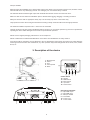
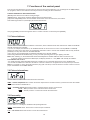
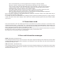
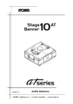
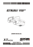
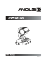
3. Description of the device
1 - Moving head
2 - LEDs
3 - Arm
4 - Control panel
5 - Base
Control board
12 - Display
13 - Mode-button
14 - Enter-button
15 - Up-button
16 - Down-button
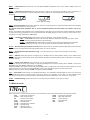
Rear panel of the base
6 - 3-pin DMX output
7 - 3-pin DMX input
8 - Transport handle
9 - Fuse holder
10 - Power cord
11 - Power switch
5
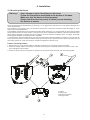
4. Installation
4.1 Mounting the fixture
Warning !
Use 2 clamps to mount the fixture on the truss.
Follow the instructions mentioned at the bottom of the base.
Make sure that the device is fixed properly!
Ensure that the structure (truss) to which you are attaching
the fixtures is secure.
The moving-head can be placed directly on the stage floor or rigged in any orientation on a truss without altering its operation characteristics.
The installation of the projector has to be built and constructed in a way that it can hold 10 times the weight for 1 hour
without any harming deformation.
The installation must always be secured with a secondary safety attachment, e.g. an appropriate catch net. This secondary
safety attachment must be constructed in a way that no part of the installation can fall down if the main attachment fails.
When rigging, derigging or servicing the fixture staying in the area below the installation place, on bridges, under high
working places and other endangered areas is forbidden.
For overhead use, always install a safety-rope that can hold at least 10 times the weight of the fixture. You must only use
safety ropes with screw-on carabines. Pull the safety-rope through the two apertures on the bottom of the base and over
the trussing system etc. Insert the end in the carabine and tighten the fixation screw.
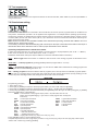
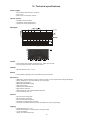
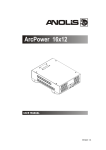
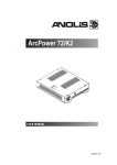
Fixation via Omega holders
1. Bolt the clamp (1) to the omega holder (4) with M12 bolt and lock nut through the hole in the holder.
2. Fasten the omega holders to the bottom of the base by inserting both quick-lock fasteners (3) into the holes of the
base and tighten fully clockwise.
3. Fasten the safety-rope (2) through the two apertures on the bottom of the base and over the trussing system.
1-Clamp
2-Safety-rope
3-Quick-lock fastener
4-Omega holder
6
4.2 Connection to the mains
Connect the fixture to the mains with the power cord.
If the plug on the flexible cord is not the right type for your socket outlets,do not use an adaptor,but remove the plug from
the cord and discard.Carefully prepare the end of the the supply cord and fit a suitable plug.
The earth has to be connected!
The occupation of the connection-cables is as follows:
Cable (EU) Cable (US)
Pin
International
Brown
Black
Live
L
Liht blue
White
Neutral
N
Yellow/
Green
Green
Earth
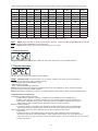
4.3 DMX-512 connection/connection between fixtures
The fixture is equipped with 3-pin XLR sockets for DMX input and output. Only use a shielded twisted-pair cable designed
for RS-485 and 3-pin XLR-plugs and connectors in order to connect the controller with the fixture or one fixture with
another.
Occupation of the XLR-connection:
DMX - output
DMX-input
XLR mounting-sockets (rear view):
XLR mounting-plugs (rear view):
1 - Shield
2 - Signal (-)
3 - Signal (+)
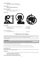
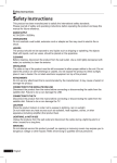
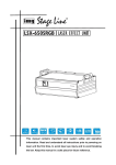
Building a serial DMX-chain:
If you are using the standard DMX-controllers, you can connect the DMX-output of the controller directly with the DMX-input of the first fixture in the DMX-chain. If you wish to connect DMX-controllers with other XLR-outputs, you need to
use adapter-cables.
Connect the DMX-output of the first fixture in the DMX-chain with the DMX-input of the next fixture. Always connect output
with the input of the next fixture until all fixtures are connected.
Caution: At the last fixture, the DMX-cable has to be terminated with a terminator. Solder a 120 Ohm resistor between
Signal (–) and Signal (+) into a 3-pin XLR-plug and plug it in the DMX-output of the last fixture.
Building a master/slave-chain:
Connect the DMX-output of the master fixture in the data-chain with the DMX-input of the first slave. Always connect output
with the input of the next slave until all slaves are connected (up to 32 fixtures).
Caution: It’s necessary to insert the XLR termination plug (with 120 Ohm) into the input of the master fixture and into the
output of the last slave fixture in the link in order to ensure the proper transmission on the data link.
DMX operation
Master/slave operation
7
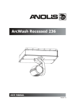
4.4 Fitting the frost filtr
The ArcWash 236 RG is supplied with clear front glass (factory fitted) and two types of frost filters (films). If you wish to
use a diffusive light ,follow the steps to install desired frost filter:
2.Put the frost film on the front glass and centre the holes
1.Remove the ring (1) from the forefront
in the film on the holes in the holder of the glass.
of the head by loosening both fastening
3.Put the ring carefully back and tighten both fastening
screws (2).
screws.
1
3
2
8
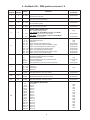
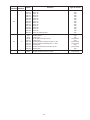
5. ArcWash 236 - DMX protocol,version 1.0
Mode 1 Mode 2
Channel Channel
1
1
2
3
2
4
Value
3
Pan
Pan movement by 530°
proportional
0 - 255
Pan Fine
Fine control of pan movement
proportional
0 - 255
Tilt
Tilt movement by 280°
proportional
0 - 255
Tilt fine
Fine control of tilt movement
proportional
1 - 255
1 - 255
6
7
9
4
10
5
11
6
12
Pan/Tilt speed, Pan/Tilt time
Max. speed (tracking mode)
P./T. speed-set Speed Mode in menu: P./T. Mode
Speed from max. to min. (vector mode)
P./T. time - set Time Mode in menu: Pan/Tilt Mode
Time from 0,1 s to 25.5 s.
step
proportional
proportional
0-9
10 - 31
32 - 63
64 - 95
96 - 127
128 - 159
160 - 191
192 - 223
224 - 255
Pan/Tilt macro selection
Disabled pan/tilt macro
Reserved
Figure of circle (from small to large)
Figure of horizontal eight (from small to large)
Figure of vertical eight (from small to large)
Figure of rectangle (from small to large)
Figure of triangle (from small to large)
Figure of five-pointed star (from small to large)
Figure of cross (from small to large)
step
step
proportional
proportional
proportional
proportional
proportional
proportional
proportional
0
1-127
128-129
130-255
Pan/Tilt macro speed
Set pan/tilt speed (channel 5) at 0 DMX
No macro generation
Macro generation from fast to slow-forwards
No macro generation
Macro generation from slow to fast-backwards
step
proportional
step
proportional
Special functions
0 - 129 Reserved
130 - 139 Pan/tilt reset
140 - 255 Reserved
8
Type
of control
0 - 255
0
5
Function
step
0-255
Red LED
Red LED saturation control (0-100%)
proportional
0-255
Green LED
Green LED saturation control (0-100%)
proportional
0-255
Blue LED
Blue LED saturation control (0-100%)
proportional
0-7
8-15
16-23
24-31
32-39
40-47
48-55
56-63
64-71
72-79
80-87
88-95
96-103
104-111
112-119
120-127
128-135
Colour MACRO SELECTION
No function
Macro 1
Macro 2
Macro 3
Macro 4
Macro 5
Macro 6
Macro 7
Macro 8
Macro 9
Macro 10
Macro 11
Macro 12
Macro 13
Macro 14
Macro 15
Macro 16
9
step
step
step
step
step
step
step
step
step
step
step
step
step
step
step
step
Mode 1 Mode 2
Channel Channel
12
13
7
14
8
Value
Function
Type of control
136-143
142-151
152-159
160-167
168-175
176-183
184-191
192-199
200-207
208-215
216-223
224-231
232-239
240-247
248-255
Macro 17
Macro 18
Macro 19
Macro 20
Macro 21
Macro 22
Macro 23
Macro 24
Macro 25
Macro 26
Macro 27
Macro 28
Macro 29
Macro 30
Macro 31-Rainbow effect
0-31
32-63
64-95
96-127
128-143
144-159
160-191
192-223
224-255
SHUTTER/STROBE
Shutter closed
Shutter open
Strobe-effect from slow to fast
Shutter open
Opening pulses in sequences slow--> fast
Closing pulses in sequences fast --> slow
Shutter open
Random strobe-effects from slow to fast
Shutter open
step
step
proportional
step
proportional
proportional
step
proportional
step
DIMMER
Dimmer intensity from 0% to 100%
proportional
0-255
10
step
step
step
step
step
step
step
step
step
step
step
step
step
step
step
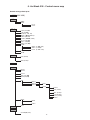
6. ArcWash 236 - Control menu map
Default settings=Bold print
A001 (001-498)
InFo
PErS.
MAn.C.
tEMP.
VErS.
IC1.b.
IC2.b.
r.PAn (On,Off)
r.tilt (On,Off)
MI.SE (1...10...20)
dM.Pr. (Mod.1,Mod 2)
FEEd. (On,Off)
P.t.Mo. (SP.Mo.,ti.Mo.)
bL.Co.(On,Off)
bl.P.t. (On,Off)
BALA. (On,Off)
C.bAL.
rEd.b. (0..200..255)
GrE.b. (0...255)
bLu.b. (0..215..255)
I.bli. (On,Off)
dFSE
Pan (0-255)
:
dimr (0-255)
tESt
St.AL.
EPG.1
EPG.2
:
PrG.6
Auto (On,Off)
Audi.(On,Off)
Edit
MaSt.
rESE.
SLA.
EPG.1
EPG.2
EPG.3
St.01
:
St.30
P.End
PAn (0-255)
:
dimr. (0-255)
F.tim.(0-255)
S.tim. (0-255)
COPY.
EPG1
:
PrG.6
SPEC.
uPd.M.(No,Yes)
11
7. Functions of the control panel
The control panel situated on the front panel of the base offers several features. You can simply set the DMX address,
run programs, make a reset and also use many functions for setting the fixture behaviour.
Control elements on the control board:
[MODE] button-leaves menu without saving changes.
[ENTER] button- enters menu,confirms adjusted values and leaves menu.
[UP] button and[DOWN] button- moves between menu items on the the same level, sets values.
After switching the fixture on,the display shows the initial screen:
Use [UP],[DOWN] to browse through the menu. To select a function or submenu,press [ENTER].
7.1 Fixture Address
Use this menu to set the DMX start address of the fixture, which is defined as the first channel from which the ArcWash
236 will respond to the controller.
If you set, for example, the address 15, the ArcWash 236 will use the channel 15 to 28 for control (if Mode 1 is selected).
Please, be sure that you don’t have any overlapping channels in order to control each ArcWash 236 correctly and independently from any other fixture on the DMX data link.
If two, three or more ArcWash 236 are addressed similarly, they will work similarly.
After having addressed all ArcWash 236, you may now start operating these via your lighting controller.
Note: After switching on, the ArcWash 236 will automatically detect whether DMX 512 data is received or not.
If there is no data received at the DMX-input, the display will start to flash „A001” with actually set address.
This situation can occur if:
- the 3 PIN XLR plug (cable with DMX signal from controller) is not connected with the input of the ArcWash 236.
- the controller is switched off or defective, the cable or connector is defective or the signal wires are swap in the input connector.
Note: It’s necessary to insert the XLR termination plug (with 120 Ohm) to the last fixture in the link in order to ensure
proper transmission on the DMX data link.
7.2 Fixture informations
Use this menu to read an useful information about the fixture.
tEMP ---Fixture temperature.The function shows the temperature in the fixture head (°C).Please note that the outside
temperature should not exceed 40° C.
VErS. --- Software version.Select this function to read the software version of processors:
IC1.b.--- Main processor on the main board in the fixture base
IC2.b.--- Pan/tilt processor on the main board in the fixture base
7.3 Personality
Use this menu to to modify the ArcWash 236 operating behavior.
r.PAn --- Pan reverse.Select this function to invert the pan movement.
r.tilt --- Tilt reverse.Select this function to invert the tilt movement.
12
DM.Pr. --- DMX preset.Select this item to choose desired DMX mode.Please refer to the chapter "DMX protocol" for
detail description.
Mi.SE. --- Microphone sensitivity.Select this function to adjust the microphone sensitivity from 1(maximum) to
20(minimum).If the sensitivity is correctly adjusted,the upper segment of the first digit blinks in the bass beat.
Examples:
underexited
right level
(upper segment blinks)
overexited
FEEd --- Pan/Tilt feedback.This function allows to return the mowing head to the required pan/tilt position after changing
the position by external force (e.g.by stroke).
Be careful, the Pan/Tilt Feedback OFF is not the standard operation and the head of the fixture can be demaged!
Note: If the feedback was switched off ,the pan/tilt-position is changed by an external force and the feedback is switched
on again,the moving head might not to be synchronized with the DMX signal.You have to make a reset in order to synchronize the moving head with the DMX signal.
P.t.Mo. --- Pan/tilt movement mode.Use this menu to set the character of the pan/tilt movement.
ti.Mo. --- Time mode.Pan and tilt will move with different speeds and they will come at the same
time to end point (pan and tilt sets its optimal speed).
SP.Mo. --- Speed mode.Pan and tilt will move with the same speed as adjusted at the channel 5
(Pan/Tilt speed).E.g. pan will come to the end point and wait for tilt,which has longer track.
bL.Co. --- Blackout during movement correction.Select this function to enable the blackout during the head movement
correction (if the moving head lost its right pan/tilt position for a short moment).
bl.P.t. --- Active Blackout while Pan/Tilt moving: - Use this function if you wish to close the light output during
pan/tilt changes.
bALA. --- Balance.Select this function to enable (On) or disable (OFF) the white balance which is set in "White colour
balance" menu below.If this function is set OFF,ArcWash 236 will use maximum values (255) of saturation for red, green
and blue channel.
C.bAL. --- White colour balance. Using this menu you can set the white balance:
1. Browse through the menu by pressing the [UP] and [DOWN] buttons until the display shows "C.bAL." menu.Press
[ENTER] button and "rEd.b." will appear on the display.
2.Press [ENTER] button again and use [UP] and [DOWN] buttons to adjust the new maximum value required for the red
channel.Confirm your choice by pressing [ENTER].Use the [UP] and [Down] buttons to select next colour.
3.Repeat step 2 for green channel "GrE.b." and for blue channel "bLu.b".
i.bLi. --- Initial blink.If this function is on,ArcWash 236 makes auto-calibration (All LEDs light on 100% for a short time)
after switching the fixture on.If this function is set off,you have to set manually every colour on max.brightness after
switching on the driver before starting regular operating.This action should last min. one second for every colour.
dF.SE. --- Default Settings .Select this option to reset all fixture personalities to the factory values.
7.4 Manual mode
Select this menu to control channel effects by control buttoms on the control board without an external controller.
PAn
a coarse pan movement
GrEE a green LED saturation
F.PAn a fine pan movement
bLuE a blue LED saturation
tilt
a coarse tilt movement
MACr a colour macros
F.tilt
a fine tilt movement
Stro.
a strobe,shutter
SpEd a pan/tilt speed
dimr
a dimmer
P.t.SE. a pan/tilt macro selection
P.t.SP. a pan/tilt speed
Func. a special function
rED
a red LED saturation
13
7.5 Test sequences
Use this menu to to run a demo-test sequences without an external controller, which will show you some possibilities of
using ArcWash 236.
7.6 Stand-alone setting
The fixtures on a data link are not connected to the controller but can execute pre-set programs which can be different for
every fixture. “Stand-alone operation” can be applied to the single fixture or to multiple fixtures operating synchronously.
Synchronous operation of multiple fixtures requires that they must be connected on a data link and one of them is set as
a master (“MSt“) and the rest as the slaves (“SLA“). Up to 32 fixtures can be connected in master/slave chain.Only one
fixture can be set as the master.
Note: Disconect the fixtures from the DMX controller before master/slave operating, otherwise data collisions can occur
and the fixtures will not work properly!
It’s necessary to insert the XLR termination plug (with 120 Ohm) into the input of the master fixture and into the output of
the last slave fixture in the data link in order to ensure proper transmission on the data link.
Operating multiple fixtures in stand-alone mode.
1.Select one fixture and set it as a master and select a program which is to be played (Menu path: "St.AL."--->"MASt.").
2.The rest of the fixtures set as slaves (Menu path: "St.AL."--->"SLA.").
3.Build the master/slave chain.(See chapter “DMX-512 connection and Master/Slave connection“).
Audi --- Music trigger.Select this function to enable the sound control of the running programs via the built-in microphone.
EPG1-PrG.6 --- Fixture programs.By pressing [ENTER] selected program will run in a loop.
Auto. --- Automatically playback. If this function is on, the fixture in DMX mode remembers last running program and
this program will run after switching the fixture on .
Edit --- Editing program.The fixture includes 6 built-in programs (PrG.1-PrG.6) and 3 free editable programs (EPG.1EPG.3) each up to 30 steps.Every program step has a fade time-the time during which effects (except pan/tilt) go to the
current step and a standing time-the time,during which effects last in the current step.
Programming procedure:
1. Enter "Edit." menu
2. Press [UP] or [DOWN] to select the desired program which you wish to edit and press [ENTER].
3. Press [UP] or [DOWN] to select the desired program step ("St.01" - "St.30") and press [ENTER].
4. Press [UP] or [DOWN] to select the desired item and press [ENTER] button.Now you can edit by using [UP] or [DOWN]
buttons the DMX values of selected item:
P.End. - a total number of the program steps (value 1-30).This value must be set
before start programming(e.g. if you want to create program with 10 steps,set
P.End=10).
PAn
a coarse pan movement
GrEE a green LED saturation
F.PAn a fine pan movement
bLuE a blue LED saturation
tilt
a coarse tilt movement
MACr a colour macros
F.tilt
a fine tilt movement
Stro.
a strobe,shutter
SpEd a pan/tilt speed
dimr
a dimmer
P.t.SE. a pan/tilt macro selection
P.t.SP. a pan/tilt speed
rED
a red LED saturation
F.tim. - fade time,value 0-255 *
S.tim. - standing time,value 0-255 *
COPY. - copying the current prog. step to the next prog. step.
Press [ENTER]-button to confirm adjusted value.
5.Repeat steps 3 and 4 for next prog.step.If you want to copy current prog. step to the next prog.step, select option
"COPY."and confirm it by pressing [ENTER].
14
*Both Fade time and Standing time use the same conversion table in order to convert DMX value to the time value:
DMX
Time
[sec.]
DMX
Time
[min.]
DMX
Time
[min.]
DMX
Time
[min.]
DMX
Time
[min.]
1
0.1
50
4.2
105
18.4
160
42.7
215
77
2
0.4
55
5
110
20.2
165
45.4
220
80.7
5
2.5
60
6
115
22
170
48.2
225
84.4
10
10
65
7
120
24
175
51
230
88.2
15
22.5
70
8.2
125
26
180
54
235
92
20
40
75
9.4
130
28.2
185
57
240
96
25
62.5
80
10.7
135
30.4
190
60.2
245
100
30
90
85
12
140
32.7
195
63.4
250
104
35
122.5
90
13.5
145
35
200
66.7
255
108
40
160
95
15
150
37.5
205
70
45
202.5
100
16.7
155
40
210
73.5
Exact expression of the time value follows the equation: time[sec.]=(DMX value)2/10.
MASt. --- Master.Enter this menu if you want to set the the fixture as a master.Use [UP] and [DOWN] buttons to select
desired program and press [ENTER] to confirm selection.
SLA. --- Slave.Select this menu if you want to set the the fixture as a slave.
7.6 Reset function
This option enables the ArcWash 236 to index all effects and return them to their standard positions.
7.7 Special functions
Use this menu for special services like software update.
uPd.M. ---Updating mode.Using this function you can update software in the fixture via PC and serial link.
The following are required in order to update software:
- PC running Windows 95/98/2000/XP or Linux
- DMX Software Uploader
- Flash cable RS232/DMX (No.13050624)
Note1:Software update should execute a qualified person.If you lack qualification, do not attempt the update
yourself and ask for help your ROBE distributor.
Note 2:DMX address, IP address ,programs 1-3 and all functions in menu "PErS" will be set to their default values.
To update software in the fixture:
1.Installation of DMX Software Uploader.
1.DMX Software Uploader program is available from the ROBE web site at WWW.robe.cz.
2.Make a new directory ( e.g. Robe_Uploader) on your hard disk and download the software to it.
3.Unpack the program from the archive. If the Robe fixture is produced in magnetic and electronic
ballast version, name of DMX Software Uploader is the same for both versions.
2.Fixture software updating.
1.Determine which of your COM port is available on your PC and connect it with to the DMX input
of the fixture using the uploading cable. Do not extend this cable! Disconnect the fixture from the
other fixtures in DMX chain! Turn on the computer and the fixture. Make sure the lamp is
switched off.
2.Switch the fixture to the update mode by selecting the option Updating mode in menu Special
Functions on the fixture control panel:SPEC-->UPd-->yES.(From this option you cannot return back
to the main menu. If you do not want to continue in software update, you have to switch off and on the fixture
to leave this option!)
15
3.It is recommended that you exit all programs before running the Software Uploader.
4.Start the Software Uploader program. Select desired COM and then click Connect button.
If the conection is OK, click Start Uploading button to start uploading. It will take several minutes to
perform software update. If the option "Incremental Update"isn´t checked ,all processors will be
updated (including processors with the same software version).
If you wish to update only later versions of processors, enable the Incremental Update check box.
Avoid interrupting the process. Update status is being displayed in the list window.
When the update is finished, the line with the text “The fixture is successfuly updated‘ will appear in
this window and the fixture will reset with the new software.
Note: In the case of interruption of the upload process (e.g. power cut), the fixture remains in the update mode and you
have to repeat the software update again.
For example: The fixture was switched off before finishing software upload. After switching the fixture on again, the fixture
is still in the update mode and the display is dark. Restart the Software Uploader program and repeat software update
from your PC.
8. Power down mode
This mode omits fixture reset after switching the fixture on and lowers motor powers of the fixture. „Power down mode”
is useful in special casech. g. if the fixture is in a flight case and you want to set its DMX address without taking it out
from the case. To enter „Power down mode”, press and hold [UP] and [DOWN] and at the same time switch on the Power
switch. The following message appears on the display: “P.d.Mo.”
Press [ENTER] to activate „Low power mode” without fixture reset. Now you can set features and behaviour of the fixture
by using “Pers.” menu. If you want to go „normal operation mode”, execute fixture reset.
Note: All motors in “Power down mode” are deactivated.
9. Error and information messages
PA.Er. (Pan-yoke movement error)
This message will appear after the reset of the fixture if the yoke’s magnetic-indexing circuits malfunction (sensors failed
or magnet missing) or the stepping motor is defective. (Or its driving IC on the main PCB). The yoke is not located in the
default position after the reset.
ti.Er. (TILT-head movement error)
This message will appear after the reset of the fixture if the head’s magnetic-indexing circuit malfunctions (sensor failed
or magnet missing) or the stepping motor is defective. (Or its driving IC on the main PCB). The head is not located in the
default position after the reset.
16
10. Technical specifications
Power supply
- Input Voltage:100-240V AC, 50/60 Hz
- Fuse:T 2 A
- Max.Pover Consumption:135 VA
Optical system
- 36 RGB Luxeon K2 LEDs
- Standard 6° beam angle lenses
- Optional 25° beam angle lenses
Beampath
Strobe
- Strobe effect with variable speed (max. 25 flashes per second)
- Preprogrammed random strobe pulse-effects
Dimmer
- Smooth dimmer from 0 - 100 %
Motors
- 2 high quality stepping motors controlled by microprocessors
Electronics
- Addressing, special functions setting, manual control via control panel with 4-digit LED display
- Built-in analyzer for easy fault finding, error messages
- Bilt-in demo sequences
- Black-out while head moving
- Silent fans cooling
- Digital serial input DMX-512
- Master/slave operation
- DMX-control via every standard DMX controller
- control channels: 8 or 14
Pan/Tilt
- Pan movement range 530°
- Tilt movement range 280°
- 8/16 bit movement resolution
- Automatic pan/tilt position correction
- Remotely controllable speed of pan/tilt movement for easy programming
Rigging
- Stands directly on the floor
- Mounts horizontally or vertically with 2 Omega holders
- 2 truss orientation
- Safety cord attachment point
17
Data input/output
- 3-pin XLR male socket for DMX data input
- 3-pin XLR female socket for DMX data output
Temperatures
- Maximum ambient temperature: 40° C
- Maximum housing temperature: 65° C
Minimum distances
- Min. distance from flammable surfaces: 0.5 m
- Min. distance to lighted object: 0.7 m
Dimensions
Weight (net)
8.8 kg
Accessories
- Mounting bracket Omega CL assembled (2 pieces) .....................No. 99010420
- Frost film filter (soft).......................................................................No. 14060091
- Frost film filter (dense)...................................................................No. 14060092
Optional accessories:
- Flash cable RS232/DMX ...............................................................No.13050624
11. Maintenance and cleaning
It is absolutely essential that the fixture is kept clean and that dust, dirt and smoke-fluid residues must not build up on or
within the fixture. Otherwise, the fixture‘s light-output will be significantly reduced. Regular cleaning will not only ensure
the maximum light-output, but will also allow the fixture to function reliably throughout its life.
A soft lint-free cloth moistened with any good glass cleaning fluid is recommended, under no circumstances should alcohol
or solvents be used!
DANGER !
Disconnect from the mains before starting any maintenance work
The front objective glass will require weekly cleaning as smoke-fluid tends to building up residues, reducing the light-output
very quickly. The cooling fans should be cleaned monthly.
The interior of the fixture should be cleaned at least annually using a vacuum-cleaner or an air-jet.
More complicated maintenance and service operations are only to be carried out by authorized dealers.
Replacing the fuse
If the lamp burns out, the fine-wire fuse of the device might fuse, too. Only replace the fuse by a fuse of same type and rating.
Before replacing the fuse, unplug mains lead.
Procedure:
1) Unscrew the fuseholder on the rear panel of the base with a fitting screwdriver from the housing (anti clockwise).
2) Remove the old fuse from the fuseholder.
3) Install the new fuse in the fuseholder.
4) Replace the fuseholder in the housing and fix it.
Specifications are subject to change without notice.
18
19