1
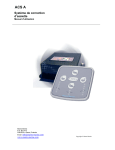
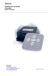
ACS R/RP Attitude Control System User’s manual Mente Marine Vaasa, Finland [email protected] www.mente-marine.com Contents Introduction ............................................................................................................................ 3 Symbols and abbreviations......................................................................................................................................3 Security ....................................................................................................................................................................3 Product disposal ......................................................................................................................................................3 Theory of operation ............................................................................................................... 4 Roll and pitch axes ..................................................................................................................................................4 Turning detection .....................................................................................................................................................4 Adaptive system.......................................................................................................................................................5 Off the plane ............................................................................................................................................................5 Position estimation...................................................................................................................................................5 Auto / Manual mode.................................................................................................................................................5 Installation .............................................................................................................................. 6 Drill the holes ...........................................................................................................................................................6 Connection ............................................................................................................................. 7 Hydraulic trim tabs ...................................................................................................................................................7 Electromechanical trim tabs.....................................................................................................................................8 Ignition key...............................................................................................................................................................8 Supply voltage .........................................................................................................................................................8 Calibration .............................................................................................................................. 9 Verify connection................................................................................................................. 10 Usage .................................................................................................................................... 11 Attitude setting .......................................................................................................................................................11 Fine adjustment .....................................................................................................................................................11 Adjusting gain ........................................................................................................................................................12 Retraction...............................................................................................................................................................12 Shut down ..............................................................................................................................................................12 Specifications....................................................................................................................... 13 Troubleshooting................................................................................................................... 14 Indicators ...............................................................................................................................................................14 Supply voltage .......................................................................................................................................................14 Warranty policy .................................................................................................................... 15 2014 Mente Marine. All rights reserved. 2 Introduction This user’s manual describes the installation and usage of the ACS RP attitude control system from Mente Marine. It is available in print and in Pdf format at www.mente-marine.com. Symbols and abbreviations ACS LED Attitude Control System Light Emitting Diode Security Switch off the main circuit breaker or put the ACS into manual mode before lifting or transporting the boat. Should the automatics engage during transport, the trim tabs may be damaged. Product disposal The WEEE Directive requires the recycling of waste electrical and electronic equipment. 3 Theory of operation The deep-V hulls of modern pleasure boats are designed to provide you with a smooth ride in rough water. The deeper the V, the more need for trim tabs to keep the boat levelled. A Roll or sideward’s inclination is dependent on the wind and passenger location. The longitudinal inclination, also called the trim angle, depends on the speed and loading. When the course is changed, winds change direction and you need to trim the boat. When passengers move, trim again. This need, to constantly adjust the trim tabs, takes the driver’s attention, which can even be a safety risk during high-speed operations. ACS takes care of the work for you. When changing course, winds shift, or passengers move, the attitude of the boat is automatically corrected by adjusting the trim tabs. Roll and pitch axes Both ACS R and ACS RP automatically adjust the boat to the optimum attitude in the roll axis, eliminating heeling. This is especially important for small and fast boats. ACS RP automatically adjusts the boat to the optimum attitude in the pitch axis, improving visibility and also enabling speeds in the “semi-planing” range. It also improves the “hole shot”. Owners of large boats may find this feature particularly useful. Turning detection While making a turn, the boat leans inwards. Thanks to the built-in gyros, the system is able to detect heading changes and prevent automatic corrections while turning. Unnecessary adjusting is avoided and the boat exits the turn with the optimum attitude. The AUTO indicator blinks while making the turn to indicate that the ACS is blocked and not active at that moment. Once set up on a steady course again, the ACS continues measuring and correcting the attitude, taking the altered conditions into account. 4 Adaptive system ACS adapts to boats over the whole range. Thanks to the adaptive functionality, the boat is set up to the optimum running attitude, taking into account differences in size and trim tab performance. It also adapts to varying sea conditions. In calm seas, a list condition is corrected faster than in rough seas. This allows a quick reaction when needed and avoids unnecessary operations that could amplify a roll in high waves. Off the plane When slowing down, below planing speed, trim tabs lose their effect. ACS is aware of this and does not attempt to control the attitude while off the plane. When accelerating, the ACS automatically starts up, correcting the attitude back to that which is desired, even before the boat “breaks over” and reaches the cruising speed. The AUTO indicator blinks while off the plane. The blinking indicates that the automatic operation is activated, but suspended for the time being because of the slow speed. Position estimation ACS shows the trim tab position estimation by lighting an indicator LED for each trim tab. When a tab is extended, the lit up indicator LED moves downwards. No additional sensors are needed and ACS shows the trim tab position estimation for all types of trim tabs after calibration. Light sensor (Optimum visibility day and night) Auto button with indicator (Auto / Manual mode) 4 x buttons for manual control of the trim tabs LED indicator bars for trim tab position LED indicator bar for gain setting Auto / Manual mode The Auto button is used to select the mode of the ACS. Briefly pressing the auto button causes the ACS to switch between the manual and automatic mode. In the manual mode, the buttons can be used to control the attitude of the boat manually. In the automatic mode, the attitude of the boat is controlled automatically when the indicator is lit up. If it is blinking, automatic operation is suspended while the boat is turning sharply or when it is off the plane. 5 Installation ACS R and ACS RP have built-in sensors that measure the boat’s movements and should therefore be mounted upright or laying down. All angles between upright and laying down are allowed. 1) Upright 2) 3) Between upright and laying down 4) Laying down Regardless of the mounting angle, the starboard button should face the starboard side of the boat and the port button the port side. 5) Starboard button facing the starboard side 6) Port button facing the port side Drill the holes 80.0 mm (3.15") 66.5 mm (2.62") 50 mm (2") 6 Choose a location close to the helm where the control panel is easy to access and drill holes for the screws and connectors using the enclosed drill pattern. In retrofit installations, remove the old panel and use the new panel to cover the hole. Connection IMPORTANT! In retrofit installations, disconnect the wires from the old control panel before connecting the ACS. It should not be connected in parallel with the old panel. Switch off the main circuit breaker before starting the connection! Hydraulic trim tabs Hydraulic trim tabs, such as Bennett, Instatrim, QL and Trimmaster use a hydraulic pump unit to extend and retract the actuators. The pump unit is situated in the rear of the boat and connected to the battery's negative (-) terminal. From the pump unit, a wire harness is routed to the ACS. Connect the wires to the ACS terminals 3, 4, 5, 6, according to the figure that follows. Terminals 5 and 6 are connected to the pump’s motor and terminals 3 and 4 to the valves controlling the trim tabs. The table below shows the colours used by the major manufacturers of hydraulic trim tabs. Corresponding ACS markings are shown in the left column. ACS marking Instatrim (QL) Bennett Trimmaster 3 Green Red Green 4 White Green White 5 Yellow Yellow Yellow 6 Red Blue Red 1 2 3 4 5 6 7 15A(F) 10...30V dc (+) (-) 3 4 5 6 M 7 Electromechanical trim tabs Connect the starboard actuator to terminals 5 and 6 and the port actuator to terminals 3 and 4, according to the figure that follows. Verify the connection later on and change it if necessary. ACS marking Lenco Lectrotab Ultraflex Black (port) 3 Black (port) White (port) 4 White (port) Black (port) White (port) 5 Black (stbd) White (stbd) Black (stbd) 6 White (stbd) Black (stbd) White (stbd) 1 2 3 4 5 6 7 15A(F) 10...30V dc (+) (-) 3/4 5/6 Ignition key Terminal 7 may be connected to the ignition key run position. If the ignition key is connected, retraction will take place when switching off the engine. Without the ignition key connection, retraction will take place after a delay when the boat has come off the plane. Supply voltage Connect a red wire to the boat’s main circuit breaker through a fuse. Connect a black wire to the battery's negative (-) terminal. Minimum 2.5 mm2 (14 AWG) is recommended. 8 Calibration For the ACS to operate properly, it needs to know the trim tab type, position, and current consumption. This information is automatically acquired and stored in memory during calibration. Before you start, ensure that no obstacles hinder the free run of the tabs. The AUTO indicator blinks to indicate that calibration is needed. Press the uppermost and lowermost buttons simultaneously for 4 s to start the calibration. Keep the buttons depressed for another 8 s while the ACS is calibrating. The ACS will now run the trim tabs to their uppermost position. The tabs are then run downwards and back up again. This calibration may take up to 60 seconds and should not be interrupted. After completion, the indicator LED’s stop blinking. The port trim tab position is now shown by the left bar and the starboard by the right bar. 9 Verify connection IMPORTANT! After calibration, verify the connection by pressing the buttons one by one and observing the trim tabs. Check the actual movement of the tabs at the transom. For the automatics to work properly, the trim tabs have to move in the correct direction when controlling them manually. The uppermost button controls both tabs downwards. The lowermost button controls both tabs upwards. Should the trim tabs move in the wrong direction: For hydraulic trim tabs, exchange the 5 and 6 wires, for electromechanical trim tabs, reverse the wires of the actuator(s) that move in the wrong direction. The port button controls the port tab upwards first and then the starboard tab downwards. The starboard button controls the starboard tab upwards first and then the port tab downwards. Should the trim tabs move in the wrong direction: For hydraulic trim tabs, exchange the 3 and 4 wires, for electromechanical trim tabs, exchange the 3 and 4 wires with the 5 and 6 wires. 10 Usage Attitude setting Run the boat at cruising speed. Manually control the trim tabs until you find the best attitude. Then, press and hold the auto button for 4 s until the AUTO indicator is lit up. Now, the attitude is stored in the memory, and the ACS is set in the automatic mode. Fine adjustment In the automatic mode, press any of the four buttons to alter the setting 0.5 degrees in a certain direction. Press more times for a greater change. Press and hold the auto button for 4 s to store the new setting in memory. Now, if the speed is reduced, automatic control is suspended and the AUTO indicator starts to blink. The functionality is then temporarily interrupted to avoid deflecting the tabs at too low a speed. The automatic mode is re-entered every time you go out, until the ACS is put into manual mode. By pressing the AUTO button, you can toggle between the automatic and manual mode. The running attitude remains in the memory, although the main breakers are switched off. 11 Adjusting gain The gain determines how fast the ACS should correct a list condition. It can be adjusted in three steps and the default setting is step I. Step II provides a correction that is a little faster, while step III is the fastest. The setting is optimized, if a list condition is corrected without the boat leaning over to the other side and the trim tabs are not operated too often. Press the left and right button simultaneously for 4 seconds until an indicator in the middle starts to blink. Adjust the gain setting with the uppermost and lowermost buttons. The three indicator LED’s in the middle show the setting. Then, press the left and right buttons again for 4 seconds to store the setting. Retraction Retraction prevents fouling of the actuators. ACS automatically retracts the trim tabs when the boat has been off the plane for a while. If terminal 7 has been connected to the ignition, ACS will not retract the trim tabs until the engine is switched off. Shut down When not in use for a while, ACS shuts down, drawing minimal current from the battery. This feature prevents battery drain and the boat may be left for months with the main breakers on. The ACS will be activated again when there is a need to adjust the trim tabs. 12 Specifications Compliance (Hydraulic tabs) Bennett, Instatrim, Trimmaster, QL Volvo Penta, TFX Teleflex, TX Controls Compliance Lectrotab, Lenco, Eltrim, Ultraflex (Electromechanical tabs) ACS R Control in the roll axis ACS RP Control in the roll and pitch axes Boat length 15...40 feet Tab type detection Automatic Gain Automatic, adapts to the boat type Size 80 * 77.5 * 10 mm Protection by enclosure IP 68 Operating temperature -10...85 C Storage temperature -40...+85 C Supply voltage 10...30 V dc Maximum output current 18 A (When tabs activated) Current consumption 0.02 A (When idle) Approvals CE (Compliance with EMC regulations) The CE marking assures that this product complies with the requirements of the EC directive for electromagnetic compatibility. 13 Troubleshooting If a fault is found, an indicator will start to blink intensively. Indicators Trim tabs not found Check the connection! L1 Short-circuit to the positive side L2 Short-circuit to ground L3 R1 Wrong installation angle Supply voltage During a fraction of a second, when starting a trim tab motor, the current is much higher than normal and the supply wires, fuseholder and battery should be in a good condition. This is important when replacing mechanical switches with electronic equipment. Check the voltage supply by manually operating the trim tabs. If the supply is weak, the ACS will restart and flash all the indicators twice. 14 Warranty policy All ACSs (Attitude Control Systems) purchased through authorized distribution channels are guaranteed against defects of material or workmanship for a period of 24 months from date of purchase. Service will be rendered, and defective parts will be replaced without cost to you within that period, provided that the equipment does not show any evidence of an impact, liquid damage, mishandling, tampering, or chemical corrosion, operation contrary to operating instructions, or modification by an unauthorized repair shop. The manufacturer or its authorized representatives shall not be liable for any repair or alterations, except those made with its written consent and shall not be liable for damages from delay or loss of use or from other indirect or consequential damages of any kind, whether caused by defective material or workmanship or otherwise; and it is expressly agreed that the liability of the manufacturer or its representatives under all guarantees or warranties, whether expressed or implied, is strictly limited to the replacement of parts, as herein before provided. No refunds will be made on repairs performed by non-authorized service facilities. Procedure during the 24-month warranty period Any ACS that proves defective during the 24-month warranty period should be returned to the dealer from whom you purchased the equipment or to the manufacturer. If there is no representative of the manufacturer in your country, send the equipment to the manufacturer, with postage prepaid. In this case, it will take a considerable length of time before the equipment can be returned to you owing to the complicated customs procedures required. If the equipment is covered by warranty, repairs will be made and parts replaced free of charge, and the equipment will be returned to you upon completion of servicing. If the equipment is not covered by warranty, the regular charges of the manufacturer or of its representatives will apply. Shipping charges are to be borne by the owner. If your ACS was purchased outside of the country where you wish to have it serviced during the warranty period, the manufacturer's representatives in that country may charge regular handling and servicing fees. Notwithstanding this, your ACS returned to the manufacturer will be serviced free of charge, according to this procedure and warranty policy. In any case, however, shipping charges and custom clearance fees are to be borne by the sender. To prove the date of purchase when required, please keep the receipts or bills covering the purchase of your equipment for at least two years. Before sending your equipment for servicing, please make sure you are sending it to the manufacturer's authorized representatives or their approved repair shops, unless you are sending it directly to the manufacturer. Always obtain a quotation for the service charge, and only after you accept the quoted service charge, instruct the service station to proceed with the servicing. 15 Elektro-Navigation Schick & Co. GmbH Siemensstr. 35 - 25462 Rellingen Tel.: 04101/301 01 - Fax: 04101/301 333 [email protected] - www.ferropilot.de Copyright Mente Marine