1
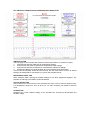
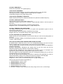
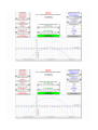
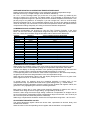
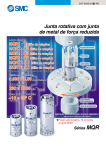
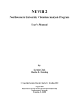
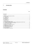
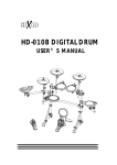
RICOH
MANUAL
RTC Crystal Deviation & Compensation Simulator V1.0
AMSTELVEEN, 22 July 2004,
INTRODUCTION
This manual explains the purpose and use of the RTC Crystal Deviation & Compensation
Simulator.
The main purpose of the simulator is to provide the calculated values to be stored in the RTC
adjustment registers in order to minimize the clock deviation caused by crystal tolerances and
temperature influences.
Furthermore it shows visual information about what happens with the clock deviation at
various parameters values as well as to understand the use of the so called Time Trimming
Function which is one key feature of Ricoh’s RTC ICs.
BEFORE YOU START……
First of all, confirm the respective RTC manual and select a proper crystal according to the
recommendations for electrical specifications for the crystal load capacitance (CL) and series
resistance (Rs).
This will guarantee a stable oscillator, preventing oscillator halt conditions during extreme
temperature conditions and the lowest power consumption.
Poor selected crystals, for example with a much higher load capacitance CL, causes extra
oscillator deviation.
It is possible to use additional external capacitors to compensate the deviation but it is not
recommended because it has effect on the performance of the oscillator and RTC power
consumption.
In case you want to use a popular 12.5pF crystal instead of using 6-8pF, please use the Time
Trimming Function in order to compensate the extra deviation without additional external
capacitors.
Take notice that only the internal clock data is compensated, any frequency deviation will be
present at the 32kHz output as it is not compensated.
In order to have a high accuracy 32kHz output you need to select a crystal which matches
best with the recommended crystal specifications.
Below an overview of crystal types which are tested with our RTC ICs.
Manufacturer
Micro Crystal
Micro Crystal
Epson
Epson
River Electec
Crystal type
MS2V-T1S
CC6V-T1A
FC-135
FC-255
TFX-01
RTC CRYSTAL DEVIATION AND COMPENSATION SIMULATOR
SIMULATOR TAB
The front page on the simulator tab shows the actual user interface, it consists of 4 parts
1. Control boxes with red characters for all deviation settings
2. Control boxes with green characters for temperature range settings
3. Control boxes with blue characters for compensation adjustment settings
4. Oscilloscope display for visual deviation and compensation result information
In this order the simulator should be used as well, use the reset button to return to default
settings, all settings will be overwritten by a macro with standard values.
REFERENCE TABLE TAB
Quick reference table, showing all possible settings for the RTC adjustment registers. The
simulator is referring to this data to make calculations
CALCULATIONS TAB
Source data for the curves shown in the simulator tool. Each curve is shown at high accuracy
in a temperature range from –40°C to 85°C in a 1°C step, containing 126 marks to draw the
curve.
CURVES TAB
Enlarged copy of the oscillator display on the simulator tab, showing full temperature and
deviation range.
CRYSTAL FREQUENCY
Fixed value of 32768Hz, the crystal frequency
OSCILLATOR FREQUENCY
Measure the oscillator frequency and set the measured value by using the slider.
The range is ±6.5Hz or ±198ppm from the centre frequency 32768Hz.
Incremental change 0.01Hz, page change 0.1Hz.
OSCILLATOR FREQUENCY DEVIATION
Display showing the frequency difference between the crystal and oscillator frequency
CRYSTAL TURNOVER POINT
Use the slider to set the peak position of the curve.
Standard it should be set to 25.0°C, however, crystal manuals mention a turnover point of
25°C ±5°C.
Use this setting to observe the effect of a different peak position.
Range 25°C ±5°C, incremental change 0.1°C, page change 0.5°C.
CRYSTAL TEMPERATURE COEFFICIENT
This setting controls the slope of the curve, the typical value expressed in ppm/°C² can be
found in the crystal manual.
Use this setting to observe the effect of a different curve slope.
Range 0.035 ±0.01, incremental change 0.001, page change 0.005.
ACTUAL DEVIATION AT TURNOVER POINT
Display showing the actual deviation in ppm and seconds per month at the peak position of
the curve.
As for the “Sec/Month” display, it is showing the deviation for an average month,
1 month = 365/12 months
APPLICATION OPERATING TEMPERATURE RANGE SETTINGS
By default these 2 sliders are set to 25°C, the corresponding display will show the same
values compared with the actual deviation value at the turnover point display.
This will change when a range is set with a minimum and maximum value for the application
operating temperature.
Deviation compensation calculations are usually done for the 25°C point only but the
application might be used in different environmental conditions.
In that case the calculation for 25°C might be not accurate anymore, for example if the
application is always used within a temperature range from 0°C to 20°C.
Use the 2 sliders to set this temperature range, the corresponding display will now show the
average deviation in this temperature range.
Also use this feature when temperature correction is required in the application by using an
external temperature sensor or for seasonal correction by using the clock date data.
Stepwise you can calculate the compensation value for each range.
Range 25°C +60°C/ –65°C, incremental change 0.1°C, page change 0.5°C.
See the next pictures for best compensation at:
1. Standard settings, -40°C to –20°C
2. Standard settings, -20°C to –0°C
3. Standard settings, 0°C to 50°C
4. Standard settings, 50°C to 70°C
5. Standard settings, 70°C to 85°C
6. Deviation +0.853Hz, temp coefficient 0.04, temp. range 10°C to 40°C, narrow range
AVERAGE DEVIATION IN OPERATING TEMPERATURE RANGE
Display showing the average deviation in the application operating temperature range.
Note that this is only a simple average value calculation defined by:
Av = Σx / n or the average value (Av) is the sum of a group of values (x) divided by the
amount of values (n) in this group. For better results, try to estimate or calculate a kind of
average temperature range for a specific period as the ambient temperature fluctuation curve
per day may be very different. An example, If you set a range from –20°C to 50°C the daily
ambient temperature is for 75% somewhere between 20°C and 30°C then adjust the settings
closer to this range. For best results, use an external temperature sensor and update the RTC
compensation settings frequently according to the actual ambient temperature.
COMPENSATION ADJUSTMENT RANGE
Deviation compensation can be done by using the Time Trimming Function, in the chart
below can be found which compensation range and step-rate is supported by the various
RTC ICs, check this out before using the simulator and be aware of the differences.
Product
Rx5C348x
R2043x
RS5C313
RS5C314
RS5C316x
RS5C317x
RS5C321x
Rx5C338A
RV5C339A
R2061x
RS5C372x
RV5C386A
RV5C387A
R2051x
R2025x
Interface
4 Wire
4 Wire
3 Wire
3 Wire
3 Wire
3 Wire
3 Wire
3 Wire
3 Wire
3 Wire
2 Wire
2 Wire
2 Wire
2 Wire
2 Wire
Time Trimming Function Supported
Wide Range
Wide & Narrow Range
None
None
None
None
None
Wide Range
Wide Range
Wide & Narrow Range
Wide Range
Wide Range
Wide Range
Wide & Narrow Range
Wide Range
COMPENSATION ADJUSTMENT VALUE
When setting any deviation value, a red curve will show visual information about the result.
The deviation can be compensated by using the compensation adjustment value slider.
Observe the display for average deviation in the operating temperature range and move the
slider in that way until the average deviation display decreases to a minimum.
A corresponding blue curve shows the result of the compensation in the oscilloscope display,
the green line shows the average deviation in the set temperature range.
When the best compensation value is set, the display background will turn to a green color
and the green line is on or closest to the X-axis.
In special cases, for example when the remaining deviation is exactly 50% of one
compensation step, 2 possible values will show a green background. (ƒ = 32768.150Hz)
The absolute remaining deviation will be the same for both positive and negative values, the
green bar is only highlighting the minimum remaining deviation.
Best result is 0ppm but in most cases some remaining deviation is present, this value is
smallest when using the narrow range setting. (if supported by the RTC IC)
However, when using the narrow range setting a maximum compensation of ±63ppm can be
set, this will limit the compensation within a temperature range from around –18°C to 66°C (at
25°C turnover point and 0.035 temperature coefficient).
Wide range compensation should be used for the full temperature range from –40°C to 85°C.
ADJUSTMENT REGISTER VALUES
The actual adjustment register values are shown here, represented in decimal, binary and
hexadecimal numbers.
Store the value in the corresponding control register and the deviation is compensated.
IMPORTANT NOTE
On the Reference Table tab in the RTC Compensation Simulator tool some columns should
provide data regarding the adjustment value in Hexadecimal and Binary code.
The data is calculated with Excel engineering functions like DEC2BIN or DEC2HEX which are
not installed by default.
In that case these columns show “#NAME” instead of the actual value, the engineering
functions can be installed by selecting the Analysis Toolpak and Analysis Toolpak-VBA AddIns from the tools menu.
FINAL REMARKS
We hope that this tool is useful when you are using our RTC ICs and trying to achieve the
best results for your application.
Feedback from users is always appreciated, this is only version 1.0, we hope to add some
new features in the next versions according to comments from engineers who are designing
new electronic applications.
For more information and datasheets about our semiconductor products please refer to our
website for the latest news.
Hans Riko Adams
Application Engineer
Semiconductor Support Centre
Ricoh Europe B.V.
Koolhovenlaan 45
1119NB Schiphol-Rijk
The Netherlands
Mail address:
P.O.Box 75640
1118ZR Schiphol
The Netherlands
Phone: +31-(0)20-5474309
Fax: +31-(0)20-5474791
Email: [email protected]
Website: http://www.ricoh.com/LSI/