1
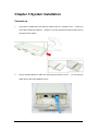
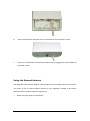
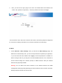
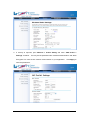
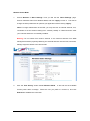
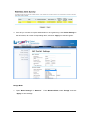
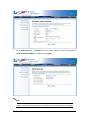
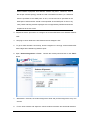
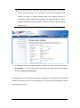
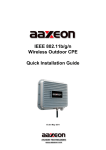
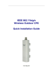
IEEE 802.11a/n Wireless Outdoor CPE
Quick Installation Guide
F3.0.4 Sep. 2011
Copyright
Copyright © 2011 all rights reserved. No part of this publication may be reproduced, adapted,
stored in a retrieval system, translated into any language, or transmitted in any form or by any
means without the written permission of the supplier.
About the Quick Installation Guide
This Quick Installation Guide is intended to guide professional installer to install the IEEE
802.11a/n Wireless Outdoor CPE.
It covers procedures to assist you in avoiding unforeseen
problems.
Conventions
Warning:
This sign indicates a warning or caution that you have to abide.
Note:
This sign indicates an important note that you must pay attention to.
Chapter 1 Introduction
Introduction
The IEEE 802.11a/n Wireless Outdoor CPE is a multi-mode last-mile broadband solution for
customers like wireless ISP (WISPs) and system integrators. By the nature of complying with
the IEEE802.11n standard and featuring high power output, the IEEE 802.11a/n Wireless CPE
supports higher bandwidth of up to 300Mbps with longer range for outdoor applications.
The IEEE 802.11a/n Wireless Outdoor CPE can be used as the access point, the customer
premises equipment (CPE), the WDS or the AP Repeater. While being as the access point, it
can be deployed outdoors to provide outdoor wireless internet service. In the other way to be
as the outdoor CPE, it can receive wireless signal over the last mile, helping WISPs deliver
internet service to the new residential and the business customer where wired broadband
internet service, such as cable and DSL, can not serve in. In addition, the easy-to-install
Wireless Outdoor CPE covers 5GHz bands, which features outstanding throughput
performance and a cost-effective design that allows users to have the reliable outdoor
equipment at the affordable price.
Chapter 2 Preparation before Installation
This chapter describes safety precautions and product information you have to know. Please
check this chapter before installing the CPE.
Professional Installation Required
Please seek assistance from a professional installer who is well trained in the RF installation
and knowledgeable in the local regulations.
Safety Precautions
To keep you safe and install the hardware properly, please read and follow these safety
precautions.
1.
If you are installing the IEEE 802.11a/n Wireless Outdoor CPE for the first time, for your
safety as well as others’, please seek assistance from a professional installer who has
received safety training on the hazards involved.
2.
Keep safety as well as performance in mind when selecting your installation site,
especially where there are electric power and phone lines.
3.
4.
When installing the CPE, please note the following things:
♦
Do not use a metal ladder;
♦
Do not work on a wet or windy day;
♦
Wear shoes with rubber soles and heels, rubber gloves, long sleeved shirt or jacket.
When the system is operational, avoid standing directly in front of it. Strong RF fields are
present when the transmitter is on.
Installation Precautions
To keep the CPE well while you are installing it, please read and follow these installation
precautions.
1. Users MUST use a proper and well-installed grounding and surge arrestor with the IEEE
802.11a/n Wireless Outdoor CPE; otherwise, a random lightening could easily cause fatal
damage to the unit.
EMD (Lightning) DAMAGE IS NOT COVERED UNDER
WARRANTY.
2. Users MUST use the “Power cord & POE Injector” shipped in the box with the CPE. Use of
other options will likely cause damage to the unit.
3. Users MUST power off the CPE first before connecting the external antenna to it. Do not
switch from built-in antenna to the external antenna from WEB management without
physically attaching the external antenna onto the CPE; otherwise, damage might be
caused to the unit itself.
Product Package
The product package you have received should contain the following items. If any of them are
not included or damaged, please contact your local vendor for support.
IEEE 802.11a/n Wireless Outdoor CPE
×1
Pole Mounting Ring
×2
Power Cord & POE Injector
×1
Product CD
×1
Note:
Product CD contains Quick Installation Guide and User Manual!
Pole Mounting Ring
- Power cord & POE Injector
Warning:
Users MUST use the “Power cord & POE Injector” shipped in the box with the CPE.
Use of other options will likely cause damage to the unit.
Chapter 3 System Installation
Connect up
1.
The bottom of IEEE 802.11a/n wireless outdoor CPE is a movable cover.
screw with a Philips screwdriver.
Loosen the
Grab the cover and pull it back harder to take it out as
the figure shown below.
2.
Plug a standard Ethernet cable into the RJ45 port labeled “LAN 1”.
cable into the RJ45 port labeled “LAN 2”.
Do not plug the
The secondary Ethernet port (labeled LAN 2) is for IP video integration.
To use it you
need to enable the secondary port in advance before connecting with the IP camera
from the CPE’s Web Management as shown below.
3.
Take out the power cord and POE injector from the gift box, and plug the power cord into
the DC port of the POE injector as the below picture shows.
4.
Put what in the Step.2 and Step.3 together by plugging the other side of the Ethernet
cable in the Step.2 into the POE port of the POE injector in the Step.3. When you finish
the Step.4, the set will be like the following picture:
5.
Press the black PWR button beside the LAN 1 Ethernet port.
6.
Attach and fasten the removable cover to the bottom of the unit with the screw.
7.
Power on the IEEE 802.11a/n Wireless Outdoor CPE by plugging the power adapter to
the power socket.
Using the External Antenna
The IEEE 802.11a/n Wireless Outdoor CPE provides two reverse SMA antenna connectors if
you prefer to use an external MIMO antenna for your application instead of the built-in
directional antenna, please follow the steps below.
1.
Remove the two plugs as circled below:
2.
Connect your external antenna to the SMA-type connectors on the bottom of the CPE.
Warning:
Users MUST power off the CPE first before connecting the external antenna to
it. Do not switch from built-in antenna to the external antenna from WEB
management without physically attaching the external antenna onto the CPE;
otherwise, damage might be caused to the unit itself.
Follow the steps described in Connect Up to finish the installation.
Pole Mounting
1.
Turn the CPE over. Put the pole mounting rings through the middle hole of it.
Note that
you should unlock the pole mounting ring with a screw driver before putting it through the
CPE as the following right picture shows.
2.
Mount the IEEE 802.11a/n Wireless Outdoor CPE steadily to the pole by locking the pole
mounting ring tightly.
Now you have completed the hardware installation of the IEEE 802.11a/n Wireless Outdoor
CPE.
Chapter 4 Configuration
Connect the IEEE 802.11a/n Wireless Outdoor CPE with your PC by an Ethernet cable
plugging in LAN port of POE injector in one side and in LAN port of PC in the other side.
Power on the CPE by POE from the supplied POE injector and press the black power button
beside the LAN1 port.
1.
Assign a static IP address to your PC which should be in the same network segment with
the CPE. As the default IP address of the CPE is 192.168.1.1, you may choose from
192.168.1.2 to 192.168.1.254. Then click OK.
2.
Open the web browser on your PC, key in the IP address (192.168.1.1) of the CPE in the
address bar, and then press Enter.
3.
Now, you will see the log-in page of the CPE. The default Name and Password are
“admin” and “password” respectively.
Enter the password and then click Login.
* Since the CPE covers “AP mode” as well as “CPE mode”, the following steps are categorized
for convenience reading to describe how to set each mode after successful log-in.
AP Mode
1. Choose Wireless > Basic Settings. Then you will see the “Basic Settings” page. The
default is AP mode already. Here, you can set the parameters to optimize your application,
or you can leave them as the default. Click “Apply” to save the parameters. In addition, for
better coverage of the AP, you may also use external MIMO antennas; if so, remember to
set the antenna setting from “Internal (16 dBi)” to “SMA Connector” after your external
antennas are physically installed.
Warning: Do not switch from built-in antenna to the external antenna from WEB
management without physically attaching the external antenna onto the CPE; otherwise,
damage might be caused to the device itself.
2. If security is required, open Wireless > Profile Setting and enter “VAP Profile 1
Settings” as below.
You may set the parameters like “Network Authentication” and “Data
Encryption” for more secure network communication in your application.
save the parameters.
Click Apply to
Wireless Client Mode
1.
Choose Wireless > Basic Settings. Then you will see the “Basic Settings” page.
Choose “Wireless Client” from Wireless Mode, and click “Apply” to save it.
Feel free to
change the other parameters to optimize your application before clicking “Apply”.
Note: For longer transmission of the CPE, you may also use an external antenna; if so,
remember to set the antenna setting from “Internal (16 dBi)” to “SMA Connector” after
your external antenna is successfully installed.
Warning: Do not switch from built-in antenna to the external antenna from WEB
management without physically attaching the external antenna onto the CPE; otherwise,
damage might be caused to the device itself.
2.
Click the “Site Survey” button beside Wireless Mode.
access points within coverage.
It will scan all the available
Select the one you prefer to connect to, and click
Selected to establish the connection.
3. If the AP you connect to require authentication or encryption keys, click Profile Settings in
the left column, fill out the corresponding items, and click “ Apply” for data encryption.
Bridge Mode
1. Open “Basic Settings” in “Wireless”.
“Apply” to save settings.
From Wireless Mode, select “Bridge” and click
2. Go to “WDS Settings ” in “Wireless”, input the MAC address of the remote bridge to
“Remote AP MAC Address 1” field and click “Apply”;
Note:
Bridge uses the WDS protocol that is not defined as the standard thus compatibility
issues between equipment from different vendors may arise.
Moreover, Tree or
Star shape network topology should be used in all WDS use-cases (i.e. if AP2 and
AP3 are specified as the WDS peers of AP1, AP2 should not be specified as the
WDS peer of AP3 and AP3 should not be specified as the WDS peer of AP2 in any
case). Mesh and Ring network topologies are not supported by WDS and should be
avoijded in all the use cases.
3. Repeat the above procedures to configure the remote IEEE 802.11a/n Wireless Outdoor
CPE.
4. Use ping to check whether the link between the two bridges is OK.
5. To get a better wireless connectivity, antenna alignment is strongly recommended after
both bridges are installed long distance apart.
6. Open “Antenna Alignment” in Tools.
Choose the remote peer and click on the “Start”
button.
7.
Wait about 5 seconds, the antenna alignment starts and performs alignment every one
second.
8.
Fix the local antenna and adjust the remote antenna elevation and horizontal direction.
During the adjustment, observe “Current RSSI” and “Signal Strength” in local bridge.
The value will refresh every 1 second. Fix the remote antenna when it reaches your
expectation. Usually, RSSI between -50 to -70dBm indicates rather good signal strength.
9.
Adjust the local antenna after fixing the remote one. During the adjustment, observe
“Current RSSI” and “Signal Strength” in the remote bridge. Fix the local antenna when it
reaches your expectation. Under AP/CPE mode where Antenna Alignment Tool is not
available, another option is provided to check the signal strength towards the connecting
AP/CPE.
Open “Connections” in “Status” as below, and click “Refresh” to view the
current signal strength of wireless connectivity.
If the signal is not so good, align the
antenna manually.
AP Repeater Mode
1. Choose Wireless > Basic Settings. Choose “AP Repeater” from Wireless Mode, and
click Apply to save it. Feel free to change the other parameters to optimize your
application before clicking Apply.
Note:
For longer transmission of the IEEE 802.11b/g/n Wireless CPE, you may also
use an external antenna; if so, remember to set the antenna setting from
“Internal (16 dBi)” to “SMA Connector” after your external antenna is
successfully installed, otherwise do not switch to “SMA Connector)” without
physically attaching the external antenna, otherwise, damage might be caused
to device itself.
2.
To establish point-to-point bridge connection, please follow the procedures described in
Bridge Mode. To connect the wireless client to the AP, please follow the procedures
described in Wireless Client Mode.
Congratulations! You have primarily completed configuration on the IEEE 802.11a/n Wireless
Outdoor CPE and they can be put into operation. For more advanced configurations, please
refer to the User manual.