1
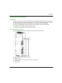
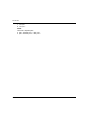
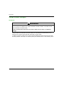
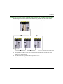
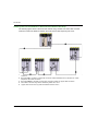
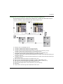
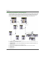
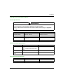
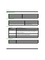
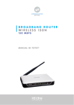
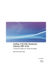
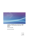
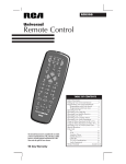
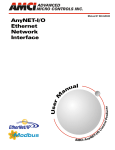
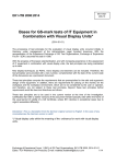
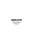
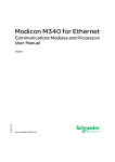
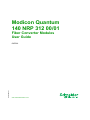
Modicon Quantum 140 NRP 312 00/01 EAV19662 04/2014 Modicon Quantum 140 NRP 312 00/01 Fiber Converter Modules User Guide EAV19662.01 04/2014 www.schneider-electric.com The information provided in this documentation contains general descriptions and/or technical characteristics of the performance of the products contained herein. This documentation is not intended as a substitute for and is not to be used for determining suitability or reliability of these products for specific user applications. It is the duty of any such user or integrator to perform the appropriate and complete risk analysis, evaluation and testing of the products with respect to the relevant specific application or use thereof. Neither Schneider Electric nor any of its affiliates or subsidiaries shall be responsible or liable for misuse of the information contained herein. If you have any suggestions for improvements or amendments or have found errors in this publication, please notify us. No part of this document may be reproduced in any form or by any means, electronic or mechanical, including photocopying, without express written permission of Schneider Electric. All pertinent state, regional, and local safety regulations must be observed when installing and using this product. For reasons of safety and to help ensure compliance with documented system data, only the manufacturer should perform repairs to components. When devices are used for applications with technical safety requirements, the relevant instructions must be followed. Failure to use Schneider Electric software or approved software with our hardware products may result in injury, harm, or improper operating results. Failure to observe this information can result in injury or equipment damage. © 2014 Schneider Electric. All rights reserved. 2 EAV19662 04/2014 Table of Contents Safety Information . . . . . . . . . . . . . . . . . . . . . . . . . . . . . About the Book. . . . . . . . . . . . . . . . . . . . . . . . . . . . . . . . Chapter 1 Introducing the 140 NRP 312 00/01 Fiber Converter Module . . . . . . . . . . . . . . . . . . . . . . . . . . . . . . . . . . . . . . . 140 NRP 312 00/01 Introduction . . . . . . . . . . . . . . . . . . . . . . . . . . . . . 140 NRP 312 00/01 Description . . . . . . . . . . . . . . . . . . . . . . . . . . . . . 140 NRP 312 00/01 LED Indicators . . . . . . . . . . . . . . . . . . . . . . . . . . 140 NRP 312 00/01 Topologies . . . . . . . . . . . . . . . . . . . . . . . . . . . . . 140 NRP 312 00/01 Specifications . . . . . . . . . . . . . . . . . . . . . . . . . . . Index EAV19662 04/2014 ......................................... 5 7 9 10 11 13 14 19 21 3 4 EAV19662 04/2014 Safety Information Important Information NOTICE Read these instructions carefully, and look at the equipment to become familiar with the device before trying to install, operate, or maintain it. The following special messages may appear throughout this documentation or on the equipment to warn of potential hazards or to call attention to information that clarifies or simplifies a procedure. EAV19662 04/2014 5 PLEASE NOTE Electrical equipment should be installed, operated, serviced, and maintained only by qualified personnel. No responsibility is assumed by Schneider Electric for any consequences arising out of the use of this material. A qualified person is one who has skills and knowledge related to the construction and operation of electrical equipment and its installation, and has received safety training to recognize and avoid the hazards involved. 6 EAV19662 04/2014 About the Book At a Glance Document Scope This document is the reference guide for the Quantum 140 NRP 312 00/01 fiber converter modules. Validity Note This documentation is valid for Unity Pro V8.0 or later. Related Documents Title of Documentation Reference Number Modicon Remote I/O Cable System Planning and Installation Guide 35014629 (English), 35014630 (French), 35014632 (German), 35014633 (Spanish) Modicon Quantum Hot Standby System User Manual 35010533 (English), 35010534 (French), 35010535 (German), 35010536 (Spanish), 35013993 (Italian), 35012188 (Chinese) Quantum With Unity Pro Experts and Communication 35010574 (English), 3501575 (French), 3501576 (German), Reference Manual 3501577 (Spanish), 3504012 (Italian), 35012187 (Chinese) Quantum With Unity Pro Hardware Reference Manual 35010529 (English), 35010530 (French), 35010531 (German), 35010532 (Spanish), 35013975 (Italian), 35012184 (Chinese) Modicon Fiber Optic Repeater’s User Guide EIO0000000872 (English), EIO0000000952 (French), EIO0000000953 (German), EIO0000000955 (Spanish), EIO0000000954 (Italian), EIO0000000956 (Chinese) You can download these technical publications and other technical information from our website at www.schneider-electric.com. EAV19662 04/2014 7 Product Related Information WARNING UNINTENDED EQUIPMENT OPERATION The application of this product requires expertise in the design and programming of control systems. Only persons with such expertise should be allowed to program, install, alter, and apply this product. Follow all local and national safety codes and standards. Failure to follow these instructions can result in death, serious injury, or equipment damage. 8 EAV19662 04/2014 Modicon Quantum 140 NRP 312 00/01 Introduction EAV19662 04/2014 Chapter 1 Introducing the 140 NRP 312 00/01 Fiber Converter Module Introducing the 140 NRP 312 00/01 Fiber Converter Module Introduction This chapter describes the 140 NRP 312 00/01 fiber converter module and how to use it within a Quantum EIO system. What Is in This Chapter? This chapter contains the following topics: Topic Page 140 NRP 312 00/01 Introduction 10 140 NRP 312 00/01 Description 11 140 NRP 312 00/01 LED Indicators 13 140 NRP 312 00/01 Topologies 14 140 NRP 312 00/01 Specifications 19 EAV19662 04/2014 9 Introduction 140 NRP 312 00/01 Introduction Using 140 NRP 312 00/01 Fiber Converter Modules WARNING UNINTENDED EQUIPMENT OPERATION Do not connect a 140 NRP 312 01 single-mode fiber converter module to a 140 NRP 312 00 multi-mode fiber converter module. Failure to follow these instructions can result in death, serious injury, or equipment damage. 140 NRP 312 00/01 fiber converter modules are an alternative method to using a dual-ring switch (DRS) to provide fiber optic communications in a Quantum EIO system. You can install 140 NRP 312 00/01 modules on Quantum local and RIO drops to: extend the total length of the Quantum EIO network (RIO drops in separate areas of a factory that are more than 100 m apart) improve noise immunity resolve possible grounding issues when using different grounding methods is required between 2 buildings You can connect a 140 NRP 312 00/01 module to any 100Mbps-based Ethernet module on a Quantum rack to extend the transmission distance. Examples: You can connect a 140 NRP 312 00/01 module to a 140 CRP 312 00 RIO head module or a 140 CRA 312 0• RIO adapter module in a Quantum EIO system. You can connect a 140 NRP 312 00/01 module to a 140 NOC 780 00 DIO head module to manage DIO devices. There are 2 models of fiber converter modules, each supporting one type of fiber cable: 140 NRP 312 00 supports multi-mode fiber cable. 140 NRP 312 01 supports single-mode fiber cable. For details on other fiber converter modules and how they operate within Quantum and M340 networks, refer to the 140 NRP 954 00/01C Fiber Optic Repeater Modules User Guide and the BMX NRP 0200/01 Fiber Converter Module User Guide. 10 EAV19662 04/2014 Introduction 140 NRP 312 00/01 Description Introduction 140 NRP 312 00/01 fiber converter modules have 2 copper ports and 2 fiber ports. The fiber ports, in both multi-mode and single-mode modules, use LC-type connectors. One fiber port is used as the transmitter signal (Tx), and the other fiber port is used as the receiver signal (Rx). There are 2 models of fiber converter modules, each supporting one type of fiber cable: 140 NRP 312 00 supports multi-mode fiber cable. 140 NRP 312 01 supports single-mode fiber cable. 140 NRP 312 00/01 Description The following figure shows the 140 NRP 312 00/01 fiber converter module: 1 2 3 4 5 6 model number, description code, color code LEDs removable door customer identification label (Fold label and place it inside door.) Ethernet port 1 Ethernet port 2 EAV19662 04/2014 11 Introduction 7 8 fiber port 1 fiber port 2 NOTE: There are 2 separate pairs: pair 1: Ethernet port 1 + fiber port 1 pair 2: Ethernet port 2 + fiber port 2 12 EAV19662 04/2014 Introduction 140 NRP 312 00/01 LED Indicators LED Description The following table describes the status of the LEDs: LED Color Ready Green Error STS1 / STS2 FX1 ACT / FX2 ACT 1 Red Green Red State Indication off The module is not powered. on The module is powered. off No error has been detected. on An error has been detected. flashing1 No link is detected on the fiber port. on A link is detected on the fiber port. flashing 1 Communication activity is detected on the fiber port. The LED flashes in a pattern of on for 200 ms and off for 200 ms. EAV19662 04/2014 13 Introduction 140 NRP 312 00/01 Topologies Introduction WARNING UNINTENDED EQUIPMENT OPERATION Do not connect a 140 NRP 312 01 single-mode fiber converter module to a 140 NRP 312 00 multi-mode fiber converter module. Failure to follow these instructions can result in death, serious injury, or equipment damage. Using 140 NRP 312 00/01 fiber converter modules in a Quantum EIO network allows you to transition from copper to fiber cable then back again to copper cable. 140 NRP 312 00/01 modules can be used to extend the distance between the local rack and an RIO drop, between 2 RIO drops, or between primary and standby racks in a Hot Standby system. 14 EAV19662 04/2014 Introduction Installing Fiber Converter Modules to Extend Distance Between the Local Rack and an RIO Drop The following figure shows a Quantum EIO network using 140 NRP 312 00/01 fiber converter modules to extend the distance between the local rack and RIO drops beyond 100 m. 1 2 3 4 5 140 NRP 312 00/01 fiber converter module interlinked with the 140 CRP 312 00 RIO head module on the local rack RIO drop with a 140 NRP 312 00/01 fiber converter module interlinked with a 140 CRA 312 •0 RIO adapter for fiber cable connection RIO drop without a 140 NRP 312 00/01 fiber converter module for copper cable connection fiber cable on the main ring used for distances greater than 100 m copper cable on the main ring used for distances less than 100 m EAV19662 04/2014 15 Introduction Installing Fiber Converter Modules to Extend Distance Between RIO Drops The following figure shows a Quantum EIO network using 140 NRP 312 00/01 fiber converter modules to extend the distance between the local rack and RIO drops beyond 100 m. 1 2 3 4 5 16 140 NRP 312 00/01 fiber converter module interlinked with the 140 CRP 312 00 RIO head module on the local rack RIO drop with a 140 NRP 312 00/01 fiber converter module interlinked with a 140 CRA 312 •0 RIO adapter for fiber cable connection RIO drop without a 140 NRP 312 00/01 fiber converter module for copper cable connection fiber cable on the main ring used for distances greater than 100 m copper cable on the main ring used for distances less than 100 m EAV19662 04/2014 Introduction Installing Fiber Converter Modules to Extend Distance Between DIO Devices The following figure shows a Quantum EIO network using 140 NRP 312 00/01 fiber converter modules to extend the distance between DIO devices beyond 100 m. 1 2 3 4 5 6 7 8 9 10 11 12 13 14 15 Quantum CPU on the primary local rack Quantum CPU on the standby local rack 140 CRP 312 00 RIO head module on the primary local rack 140 CRP 312 00 RIO head module on the standby local rack 140 NOC 780 00 DIO head module interlinked with the 140 CRP 312 00 module (3) and the 140 NRP 312 00/01 fiber converter module (7) on the primary local rack 140 NOC 780 00 DIO head module interlinked with the 140 CRP 312 00 module (4) and the140 NRP 312 00/01 fiber converter module (8) on the standby local rack 140 NRP 312 00/01 fiber converter module interlinked with the 140 NOC 780 00 DIO head module (5) on the primary local rack 140 NRP 312 00/01 fiber converter module interlinked with the 140 NOC 780 00 DIO head module (6) on the standby local rac fiber sync-link connecting the primary and standby CPUs (1 & 2) fiber sync-link connecting the primary and standby 140 CRP 312 00 modules (3 & 4) fiber sync-link connecting the primary and standby 140 NRP 312 00/01 modules (7 & 8) fiber cable on the main ring used for distances greater than 100 m dual-ring switch (DRS) used to connect DIO devices (14) to the main ring DIO device copper cable on the main ring used for distances less than 100 m EAV19662 04/2014 17 Introduction Installing Fiber Converter Modules in a Hot Standby System The following figure shows a Quantum EIO Hot Standby network using 140 NRP 312 00/01 fiber converter modules to extend the distance between the local rack and RIO drops beyond 100 m. The use of fiber converter modules are useful to help avoid noise, attenuation, and/or distant grounding when the distance between the primary and standby PLCs exceeds 100 m. 1 2 3 4 5 6 7 8 9 18 Quantum CPU on the primary local rack Quantum CPU on the standby local rack 140 NRP 312 0• fiber converter module interlinked with the 140 CRP 312 00 RIO head module on the primary local rack 140 NRP 312 0• fiber converter module interlinked with the 140 CRP 312 00 RIO head module on the standby local rack fiber sync-link connecting the primary and standby CPUs fiber sync-link connecting the primary and standby 140 NRP 312 0• fiber converter modules fiber main ring Quantum RIO drop X80 RIO drop EAV19662 04/2014 Introduction 140 NRP 312 00/01 Specifications General Specifications WARNING UNINTENDED EQUIPMENT OPERATION Do not exceed any of the rated values specified in the following tables. Failure to follow these instructions can result in death, serious injury, or equipment damage. Item 140 NRP 312 00 140 NRP 312 01 power consumption in backplane (5VDC) Typical: 760 mA Maximum: 1000 mA Typical: 760 mA Maximum: 1000 mA wavelength 1310 nm 1310 nm fiber 50/125 µm 62.5/125 µm 9/125 µm expansion 0-2 km 0-15 km Optical Transmitter Specifications Item 140 NRP 312 00 140 NRP 312 01 optical power –23.5...–14 dBm with 50/125 µm fiber cable –20...–15 dBm with 62.5/125 µm fiber cable –15...–8 dBm with 9/125 µm fiber cable rise / fall time 3 nsec or better 2.5 nsec or better transmitter disable off power –45 dBm –45 dBm Optical Receiver Specifications Item 140 NRP 312 00 140 NRP 312 01 receiver sensitivity –30 dBm –28 dBm loss of signal deassert –45 dBm –45 dBm EAV19662 04/2014 19 Introduction Mechanical Specifications weight 1 kg (2 lb) max dimensions (h x d x w) 250 x 103.85 x 40.34 mm (9.84 x 4.09 x 1.59 in) material (enclosures and bezels) polycarbonates space requirements 1 rack slot Electrical Specifications RFI immunity (IEC 1000-4-3) 80...1000 MHz, 10 V/m surge (IEC 1000-4-5) 1 kV shield to ground electrostatic discharge (IEC 1000-4-2) 8 kV air / 4 kV contact dielectric strength field to bus: 1400 Vdc channel to channel: 500 Vdc Operating Conditions temperature 0...60 ° C (32...140 ° F) humidity 90...95% RH non-condensing at 6 ° C chemical interactions Enclosures and terminal strips are made of polycarbonates. This material can be damaged by strong alkalis and various hydrocarbons, esters, halogens and ketones in combination with heat. Common products containing these include detergents, PVC products, petroleum products, pesticides, disinfectants, paint removers, and spray paints. altitude 2,000 m. When the altitude exceeds this, reduce the 60 ° C maximum operating temperature by 6 ° C/1000 m of additional elevation. vibration 10...57 Hz at 0.075 mm constant displacement amplitude 57...150 Hz at 1 g shock +/-15 g peak, 11 ms, half-sine wave Storage Conditions 20 temperature -40... 85 ° C. C -40... 185 ° F humidity 0... 95% RH non-condensing at 60 ° C free fall 1 m (3 ft) EAV19662 04/2014 Modicon Quantum 140 NRP 312 00/01 Index EAV19662 04/2014 Index 0-9 140 NRP 312 0• description, 11 specifications, 19 topologies, 14 140 NRP 312 00/01, 10 F fiber converter module 140 NRP 312 00/01, 10 topologies, 14 H Hot Standby fiber converter modules, 14 S specifications, 19 EAV19662 04/2014 21 Index 22 EAV19662 04/2014