1
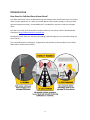
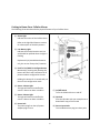
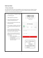
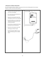
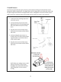
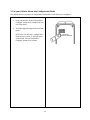
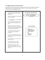
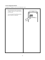
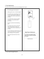
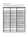
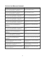
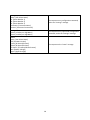
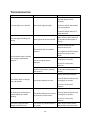
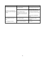
User Manual
Version 2.0
8/5/2014
Copyright 2014 PumpAlarm.com, LLC
www.PumpAlarm.com
1
CONTENTS
Introduction .................................................................................................................................................. 4
How Does the Cellular Alarm Work .......................................................................................................... 4
What Comes With Your Cellular Alarm ..................................................................................................... 5
Getting to Know Your Cellular Alarm ........................................................................................................ 6
Installation .................................................................................................................................................... 7
1. Device Activation .................................................................................................................................. 7
2. Install Backup Batteries......................................................................................................................... 8
3. Reinstall Cover ...................................................................................................................................... 9
4. Mount the Cellular Alarm ................................................................................................................... 10
5. Install Sensors ..................................................................................................................................... 11
Configuration .............................................................................................................................................. 12
1. Power On and Wait for Cellular Service .............................................................................................. 12
2. Put the Cellular Alarm in Configuration Mode ................................................................................... 13
3. Configure Notification Phone Numbers .............................................................................................. 14
4. Configure the Name of Your Cellular Alarm ....................................................................................... 15
5. Exit Configuration Mode ..................................................................................................................... 16
Testing Your Cellular Alarm......................................................................................................................... 17
1. Test Your Cellular Alarm...................................................................................................................... 17
2. Test Your Sensors ................................................................................................................................ 18
3. Test Your Backup Batteries ................................................................................................................. 18
4. Testing is Complete ............................................................................................................................. 20
Advanced Configuration ............................................................................................................................. 21
Contractor Name and Contact Configuration ......................................................................................... 21
Configuration Switches ........................................................................................................................... 21
Sensor Options ........................................................................................................................................ 22
Water Conductivity Sensor or Float (default) ..................................................................................... 22
Low Temperature Sensor .................................................................................................................... 23
General Operation ...................................................................................................................................... 24
Sensor Inputs .......................................................................................................................................... 24
Backup Battery Operation ...................................................................................................................... 24
2
Power Loss Detection ............................................................................................................................. 24
Light Blink Patterns ..................................................................................................................................... 25
Status Light (1) ........................................................................................................................................ 25
Low Battery Light (2) ............................................................................................................................... 25
Pit Sensor Lights (4 and 5) ....................................................................................................................... 25
Commands Summary .................................................................................................................................. 26
Notification Messages Summary ................................................................................................................ 27
Troubleshooting .......................................................................................................................................... 29
Specifications .............................................................................................................................................. 31
Shipping and Warranty Statement ................................................................ Error! Bookmark not defined.
3
INTRODUCTION
How Does the Cellular Water Alarm Work?
Your water alarm uses sensors to detect both high and standing water around items such as sump pits,
drains, outlets, appliances, etc . When your alarm detects water, a power outage, or low temp (with
optional temperature sensor), a loud audible alert is sounded first, and then it sends text message
alerts.
Your alarm can notify up to three phone numbers and has its own phone number, distributed after
activation at http://www.pumpalarm.com/activate.
Configure the alarm from your cell phone by sending it SMS messages (just as if you were texting any
other contact.)
This manual describes the installation, configuration, and operation of the PumpAlarm.com Cellular
Water Alarm. Please read it carefully.
4
What Comes With Your Cellular Water Alarm
We’ve packaged everything you need to monitor for the threat of water damage. The items below
come packaged with your alarm. If you’ve selected options while ordering, your sensors may vary.
(1) Cellular Alarm Unit
Contains the electronics that are used to
monitor your sensors and power, then
send text message notifications.
(2) Digital Water Sensors
a. 15 ft Digital Float Sensor
Used by the Cellular Alarm Unit
to detect water in your sump
pit, or other basin.
b. 15 ft Digital Water Sensor
Used by the Cellular Alarm Unit
to detect water on flat surfaces
(3) A/C Power Adapter
Used to provide and monitor power to
your Cellular Alarm Unit
(4) Six Mounting Straps
Used to affix the Cellular Alarm Unit to
pipes and posts as well as anchor the
float switch and water sensors.
5
Getting to Know Your Cellular Alarm
The following illustration describe the physical features of your Cellular Alarm
(1) Status Light
Indicates the status of the Cellular Alarm
Refer to the Light Blink Patterns section
for a description of the blink patterns
(2) Low Battery Light
Indicates the backup batteries are low
and should be replaced when the light is
flashing
Replace with (4) AAA alkaline batteries
only, do not use “heavy duty” batteries
(3) Push To Test/Hold To Configure Button
Momentarily pressing and releasing this
button will send a test notification to all
phone numbers configured in the unit
Holding this button for 3 seconds will put
the unit into configuration mode
(4) Sensor 1 Status Light
This light will blink on and off while
sensor 1 detects an alarm condition
(7) On/Off Switch
Turns the Cellular Alarm on and off
(5) Sensor 2 Status Light
This light will blink on and off while
sensor 2 detects an alarm condition
(8) QR Code
Scan this QR code with your smartphone to
download a copy of this manual
(6) Power Jack
The power plug from the A/C power
adapter plugs in here
(9) Sensor Input Jacks
The included sensors plug into these jacks
6
INSTALLATION
1. Device Activation
Your Cellular Water Alarm must be activated before it will communicate via text message. During the
activation process, you’ll select a payment plan and enter your billing information. Upon successful
activation, you’ll receive the phone number your unit.
1. Using a computer or smartphone, navigate
to the following link:
www.PumpAlarm.com/activate
2. Enter the 6 digit alphanumeric unit
number on the top of your unit.
3. Select your payment plan and enter your
billing information.
4. Once activation is complete, you’ll receive
an email with the phone number of your
unit.
5. Once you receive your Cellular Alarm
phone number, add the phone number to
the contact list of your cell phone.
Refer to the user’s manual of your cell
phone for more details on how to add a
new contact:
a. Create a new contact
b. Enter a name for the contact such
as “Water Alarm”
c. Enter the phone number of your
unit for the contact
7
2. Install Backup Batteries
Your Cellular Alarm Unit uses 4 AAA alkaline batteries as a backup power source to keep itself powered
up when electrical power is lost to your home. The backup batteries are not included, but must be
installed prior to using your alarm. For extreme temperature environments (cooler than 0F or hotter
than 120F, please use non-rechargeable Lithium batteries, check with battery manufacturer for
temperature specifications).
1. Remove the 4 screws on the Cellular Alarm
cover.
2. Remove the cover and place it aside.
3. Install 4 AAA batteries in the battery
holder. Use alkaline or Lithium batteries
only, do not use “heavy duty” batteries, or
rechargeable batteries.
Ensure the batteries are installed in the
correct polarity (the negative end of the
battery touches the spring in each holder).
Battery Polarity:
8
3. Reinstall Cover
The cover can now be reinstalled.
1. Reinstall the cover onto the Cellular Alarm
Unit.
2. Reinstall the 4 screws into the cover.
9
4. Mount the Cellular Alarm Unit
The recommended installation method is to strap your Alarm to the discharge pipe of your sump pit.
However, the Alarm can also be wall mounted.
1. Locate two of the mounting straps that
came with the packaging.
2. Run a mounting strap through the top
hole of the enclosure.
3. Wrap the mounting strap around the
discharge pipe, but don’t pull it tight yet.
4. Position the Alarm so it is about 4 feet
above the floor and then pull the top
mounting strap tight.
5. Run the other mounting strap through
the bottom hole of the enclosure.
6. Wrap the mounting strap around the
discharge pipe and pull it tight.
7. Plug the A/C power adapter into the
Alarm and then plug it into a 120VAC
outlet.
10
5. Install Sensors
Our Alarm kit comes with two types of sensors, with an optional 45 deg F low temperature sensor,
designed for different applications. The digital float sensor is designed for use in sump pits, basins, and
for general high water detection. The digital water sensor is designed for use on flat surfaces, such as
drains, water pans, and areas where there should never be water (this sensor is very sensitive).
1. Locate one of the mounting straps that
came with your kit.
2. Use the mounting strap to secure the
digital float sensor to the discharge pipe a
few inches below the top of the sump
basin.
3. Plug the sensor into one of the sensor
input jacks on the bottom of the Cellular
Alarm unit.
4. Position the digital water sensor in a
location where you want to detect water.
A good location is near a floor drain or
under a water heater.
5. Plug the sensor into one of the sensor
input jacks on the bottom of the Cellular
Alarm unit.
Unplugging a Sensor:
NOTE: When you unplug a sensor, avoid
pulling on the wires or they may be
damaged. Press and hold the tab down
while pulling back on the connector
housing.
11
CONFIGURATION
1. Power On and Wait for Cellular Service
Your Cellular Alarm Unit is now ready to be powered on. Once powered on, it will attempt to connect to
the cellular network.
1. Turn on the Cellular Alarm by switching on
the on/off switch (7).
2. While the Cellular Alarm unit is attempting
to connect to the cellular network, the
status light (1) will blink green.
3. Wait for the status light to turn solid
green; this can take up to 1 minute.
The status light may briefly turn red. If the
status light stays red for more than 1
minute, refer to the Troubleshooting
section of this manual.
12
2. Put your Cellular Alarm into Configuration Mode
Your cellular alarm unit must be in configuration mode before it will allow you to configure it.
1. Press and hold the “Push to Test/Hold to
Configure” button for 3 seconds until your
unit chirps twice.
2. The status light will begin to blink red and
green.
NOTE: Your unit will stay in configuration
mode for up to 1 hour, or until you press
and hold the “Push to Test/Hold to
Configure” button for 3 seconds.
13
3. Configure Notification Phone Numbers
Your Cellular Alarm will send notifications to three phone numbers. The phone numbers are configured
by sending the alarm text messages from your cell phone. You must configure at least one phone
number to receive text messaging notifications.
1. Using your cell phone, compose a new text
message to the Cellular Alarm contact
added earlier.
2. Send a text message to your Cellular Alarm
formatted as follows:
phone1
[Your Cell Phone Number]
NOTE: Your Cell Phone Number must be
10 digits long, which includes the area
code.
3. When your Cellular Alarm receives the
message, it will chirp twice and then it will
respond with a text message that contains
the current settings of your unit.
You should wait for the text message
response on your phone before
proceeding.
If an error occurs while processing your
text message, the Cellular Alarm Unit will
beep 3 times.
4. Repeat these steps for up to two other
phone numbers:
phone2 [Phone Number To Add]
phone3 [Phone Number To Add]
NOTE: These commands must be
individual text messages -- you cannot
combine multiple commands in one text
message.
14
4. Configure the Name of Your Cellular Alarm Unit
You can give your Cellular Alarm a name; it’s used in the notification messages it sends.
1. On your cell phone, compose a new text
message to your unit’s phone number.
2. Use the following in the body of the message:
name [Name]
Example: name John Doe Residence
3. When the Unit receives the message, it will
chirp twice and then it will respond with a text
message that contains the current setting.
You should wait for the text message response
on your phone before proceeding.
If an error occurs while processing your text
message, the Cellular Alarm Unit will beep 3
times.
15
5. Exit Configuration Mode
Configuration is complete, so you can exit configuration mode.
1. Press and hold the “Push to Test/Hold to
Configure” button for 3 seconds until you
hear two chirps.
2. The status light will stop blinking red and
green, and will turn solid green.
16
TESTING YOUR UNIT
1. Test Your Cellular Alarm
You can test your Cellular Alarm at any time by pressing the “Push to Test” button.
1. Momentarily press and release the “Push
to Test/Hold to Configure” button.
2. The Cellular Alarm Unit will send a test
notification to all phone numbers that
have been configured.
17
2. Test Your Sensors
The sensors can be tested at any time by submerging them in water.
1. Fill a drinking glass with tap water.
2. Submerge the sensor in the drinking glass.
3. Your Cellular Alarm should begin to sound
an alarm and each phone number you
configured will receive a notification text
message.
You should wait for the text message
notification on your phone before
proceeding.
4. Remove the sensor from the drinking
glass.
5. Your Cellular Alarm will now silence its
alarm and each phone number you
configured will receive a notification text
message.
You may need to dry off the surface of the
sensor if the Cellular Alarm Unit does not
stop sounding its alarm right away.
6. Repeat the steps above for the other
sensor.
3. Test Your Backup Batteries
18
1. Unplug the A/C power adapter from the 120
VAC outlet.
2. Once the Cellular Alarm detects that power
was lost, each phone number you configured
will receive a notification text message.
You should wait for the text message
notification on your phone before proceeding.
3. Plug the A/C power adapter back into the 120
VAC outlet.
19
4. Testing is Complete
1. Your Cellular Alarm has been tested and is
working properly.
2. You should periodically perform these tests on
the unit to ensure you are always protected.
20
ADVANCED CONFIGURATION
Contractor Name and Contact Configuration
Your Cellular Alarm allows you to configure a contractor name with associated contact information.
When this information is configured, the Cellular Alarm appends this contact information to the end of
alarm notifications (input alarms, low battery, power loss, etc.) so you know who to call in an
emergency. The Cellular Alarm must be in configuration mode to process these commands.
For example, an input alarm will be formatted as follows:
[Your Alarm] has detected a high water level for Pit #1 at [HH:MM AM/PM] on [MM/DD/YY]. Please
contact [Contractor Name] at [Contact Info] for assistance.
Command
Example
contractor [name of contractor]
contractor Bob’s Plumbing
contractor none
contractor none
contact [contact info of contractor]
contact (555) 666-7777
contact none
contact none
Description
Sets the contractor name, up to 20
characters long
Clears the name of the contractor
Sets the contact information for the
contractor, up to 14 characters long
Clears the contact information for
the contractor
Configuration Switches
Your Cellular Alarm has four configuration switches that allow you to customize additional features. The
switches are accessible by removing the cover of the Cellular Alarm. Ensure that the Cellular Alarm is
powered off before making any changes to the configuration switches.
(1) Switch 1 – Audible Alarm Enabled
On – Enable audible water alarm
Off – Disable audible water alarm
(2) Switch 2 – Text Notifications Enabled
On – Enable text message notifications
Off – Disable text message notifications
(3) Switch 3 – Configuration Mode Bypass
On –Your Cellular Alarm will process
incoming text message commands without
being in Configuration Mode
Off – Cellular Alarm must be in
Configuration Mode before it will process
incoming text message commands
(4) Switch 4 – Not Used
Not used
21
Sensor Options
Digital Water Sensor or Float (default)
The default input modes for the Cellular Alarm are for monitoring a normally-open digital water sensor
or float. If the settings have been changed previously, send the below command to revert the settings
to default in the Cellular Alarm. The Cellular Alarm must be in configuration mode to process this
command.
Command
Example
Description
Sets Input #2 in High Water
monitoring mode
input[input channel] HighWater
Input2 HighWater
(Water conductivity sensor or float
ONLY)
Response from Command
22
Low Temperature Sensor
The Cellular Alarm can be configured with the Low Temperature Sensor accessory, sold on the
PumpAlarm.com website. Consult the Temperature Sensor Installation guide that comes with the
accessory. Using the sensor requires the user to configure the input mode. The sensor is a normallyclosed device and will not function properly until the below steps are taken. The Cellular Alarm must be
in configuration mode to process this command.
Command
Example
input[input channel] LowTemp
Input2 LowTemp
Description
Sets Input #2 in Low Temperature
monitoring mode
(Normally-Closed contact ONLY)
Response from Command
Once the command is received by the Cellular Alarm, an alarm will be triggered on the input channel.
This is because the input is now looking for the normally-closed, low temperature sensor.
Snap the connector of the sensor into the input on the bottom of the Cellular Alarm unit. Once
connected, the alarm should be silenced. If the alarm does not silence, please contact Technical
Support.
You will now receive a text message alert should the temperature drop below the specified temperature
of the sensor.
To test the low temperature sensor, hold an ice cube or bag of ice against the bottom of the sensor and
wait for the alarm. Freeze spray is also a useful option for testing the sensor. Do not submerge the
sensor in water.
23
GENERAL OPERATION
Sensor Inputs
The Cellular Alarm has two inputs that can be used with Cellular Alarm sensors. When the system
detects an alarm condition for an input, it will sound an alarm, toggle the corresponding sensor status
light, and send a text notification. The Cellular Alarm will also send a text notification when the input
returns to a normal condition.
Backup Battery Operation
The Cellular Alarm uses 4 AAA batteries as a backup power source. The Cellular Alarm monitors these
batteries and sends text notification if they are low or critically low.
When the batteries are low, the system has limited battery runtime and should be replaced soon. If the
batteries are critically low, the system will not likely operate and the batteries should be replaced
immediately. When the batteries are critically low, the Cellular Alarm chirps every 30 seconds.
Power Loss Detection
The Cellular Alarm sends a text notification when electrical power is lost and restored. Power must be
lost for 5 seconds before the Cellular Alarm will send the text notifications.
The Cellular Alarm goes to sleep after 5 minutes to conserve the backup batteries while electrical power
is lost. When the Cellular Alarm detects that electrical power has been restored, it will wake up.
While the Cellular Alarm is sleeping, it is still monitoring the pit inputs. If it detects water, it will wake up
and send a text notification. It takes about 30 seconds for the Cellular Alarm to wake up.
24
LIGHT BLINK PATTERNS
Status Light (1)
Green Flashing1
Green Blinking2
Green Solid
Red Solid
Red/Green Blinking
Red Blinking Fast
Sleeping, on backup battery power
Not ready/Attempting to connect to cellular
Ready
Cannot connect to cellular network
Configuration mode
An error occurred
Low Battery Light (2)
Off
Flashing
Batteries normal
Batteries low or critically low
Pit Sensor Lights (4 and 5)
Off
Toggles On and Off with
Sounder Alarm
1
2
Water not detected
Water detected
Flashing = Light will turn on very briefly and then it turns off for two seconds
Blinking = Light will toggle on and off every second
25
COMMANDS SUMMARY
The Cellular Alarm accepts commands sent via text message. Upon receipt of commands, the Cellular
Alarm will chirp (beep) twice and send a text message response to all phone numbers configured in the
unit. If an error occurs while processing command, the Cellular Alarm will beep three times.
Command
Example
name [name of Your Alarm]
name Basement Cellular
Alarm
Description
Sets the name of the Cellular Alarm to
be used in text notifications, up to 20
characters
The default name is “Your Alarm”
Sets the first phone number to send
SMS notifications to
phone1 [phone number]
phone1 5556667777
phone1 none
phone1 none
Clears the first phone number
phone2 [phone number]
phone2 4445556666
Sets the second phone number to
send SMS notifications to
phone2 none
phone2 none
Clears the second phone number
phone3 [phone number]
phone3 3334445555
Sets the third phone number to send
SMS notifications to
phone3 none
phone3 none
Clears the third phone number
contractor [name of
contractor]
contractor Bob’s Plumbing
Sets the contractor name, up to 20
characters long
contractor none
contractor none
Clears the name of the contractor
contact [contact info of
contractor]
contact (555) 666-7777
contact none
contact none
settings
settings
status
status
input1 [LowTemp or
HighWater]
input1 LowTemp
input2 [LowTemp or
HighWater]
input2 HighWater
26
Sets the contact information for the
contractor, up to 14 characters long
Clears the contact information for the
contractor
Unit responds with the current
settings of the Cellular Alarm
Unit responds with the current status
of the Cellular Alarm
Sets the input mode for low
temperature monitoring and responds
with the current settings of the
Cellular Alarm
Sets the input mode for high water
monitoring and responds with the
current settings of the Cellular Alarm
NOTIFICATION MESSAGES SUMMARY
Message
Description
[Your Alarm Name] has detected a high water level for
input #1 at [HH:MM AM/PM] on [MM/DD/YY].
Water is detected by sensor 1.
[Your Alarm Name] has detected a high water level for
input #2 at [HH:MM AM/PM] on [MM/DD/YY.
Water is detected by sensor 2.
[Your Alarm Name] has detected a normal water level
for input #1 at [HH:MM AM/PM] on [MM/DD/YY].
Water is no longer detected by sensor 1.
[Your Alarm Name] has detected a normal water level
for input #2 at [HH:MM AM/PM] on [MM/DD/YY].
Water is no longer detected by sensor 2.
[Your Alarm Name] has detected a low temp condition
for input #1 at [HH:MM AM/PM] on [MM/DD/YY].
A low temperature condition is detected by
input 1.
[Your Alarm Name] has detected a normal temp
condition for input #1 at [HH:MM AM/PM] on
[MM/DD/YY].
Low temperature is no longer detected by
input 1.
[Your Alarm Name] has detected a low temp condition
for input #2 at [HH:MM AM/PM] on [MM/DD/YY].
A low temperature condition is detected by
input 2.
[Your Alarm Name] has detected a normal temp
condition for input #2 at [HH:MM AM/PM] on
[MM/DD/YY].
Low temperature is no longer detected by
input 2.
[Your Alarm Name] has detected that electrical power
was lost at [HH:MM AM/PM] on [MM/DD/YY].
Electrical power was lost to the Cellular Alarm.
[Your Alarm Name] has detected that electrical power
was reestablished at [HH:MM AM/PM] on
[MM/DD/YY].
Electrical power has returned to the Cellular
Alarm.
[Your Alarm Name] has low batteries at [HH:MM
AM/PM] on [MM/DD/YY].
The backup batteries are low and should be
replaced soon.
[Your Alarm Name] has critically low batteries at
[HH:MM AM/PM] on [MM/DD/YY].
The backup batteries are critically low and
replaced immediately.
[Your Alarm Name] is operating correctly at [HH:MM
AM/PM] on [MM/DD/YY].
The response to the “Push to Test” button
being pressed.
27
Settings 1/2:
Name: [Your Alarm Name]
#1: [Phone Number 1]
#2: [Phone Number 2]
#3: [Phone Number 3]
Contractor: [Contractor Name]
Contact: [Contractor Contact Info]
The response to any configuration command,
and to the “settings” message.
Settings 2/2:
Input1: [LowTemp or HighWater]
Input2: [LowTemp or HighWater]
The response to any input mode configuration
command, and to the “settings” message.
Status:
Name: [Your Alarm Name]
FW: [Firmware Version]
Input1: [N-Normal/A-Alarm]
Input2: [N-Normal/A-Alarm]
AC Power: [P-Present/NP-Not Present]
Batt: [Battery Voltage]
Signal: [Signal Strength]
The response to the “status” message
28
TROUBLESHOOTING
Problem
Cause
Remedy
Locate the Cellular Alarm to an
area with better cellular
reception
The status light is on solid red
Bad cellular signal strength
Locate the Cellular Alarm away
from metal objects
Locate the Cellular Alarm to a
higher elevation
The status light is flashing red
quickly
Some type of error has occurred
Power off the Cellular Alarm for
10 seconds and then power it
back on
Ensure the polarity of the
batteries are correct
The batteries are not installed
properly
The low battery light is flashing
even though I replaced the
batteries
You are using low quality
batteries
You did not power off the
Cellular Alarm before replacing
the batteries
The Cellular Alarm is chirping
every 30 seconds
The backup batteries are low
The negative end of the battery
touches the spring in each
holder
Use only alkaline batteries such
as Energizer or Duracell
Do not use “heavy duty”
batteries
Power off the Cellular Alarm for
10 seconds and then power it
back on
Replace the backup batteries
Use only alkaline batteries such
as Energizer or Duracell
Do not use “heavy duty”
batteries
Replace the backup batteries
All of the lights are flashing on
and off and the unit keeps
beeping
The alarm is going off even
though the sensor is not
The backup batteries are too low
to power the Cellular Alarm
The sensor has residual water on
its surface
29
Use only alkaline batteries such
as Energizer or Duracell
Do not use “heavy duty”
batteries
Power off the Cellular Alarm,
clean and dry the sensor, then
submerged in water
The sensor is dirty
The sensor is dirty
The alarm is not going off even
though the sensor is submerged
in water
A wire pulled out of the
connector on the sensor or the
connection to unit input jack is
loose.
Text messages arrive out of
order
Poor signal strength
Text messages arrive late
Cellular network congestion
30
power the Cellular Alarm on
Power off the Cellular Alarm,
clean and dry the sensor, then
power the Cellular Alarm on
Push both wires firmly into the
connector on the sensor and
push connector firmly into input
jack
Contact us for a replacement
sensor
Locate the Cellular Alarm to an
area with better cellular
reception
No remedy
SPECIFICATIONS
Operating Temperature: 32 degrees F to 150 degrees F
Operating Humidity: 0-90% RH, non-condensing
Cellular Radio: CDMA Dual Band 1xRTT (CDMA2000) 800/1900 MHz
Certifications: FCC Parts 15, 22, 24; RoHS compliant; IC: RSS-132 & 133
Antenna: Integrated, on board
Input Voltage: 12 VDC +/- 10%
Input Current: 0.5 A (max)
Backup Batteries: Non-rechargeable, AAA size, requires 4 alkaline batteries
Sounder: 2.9 kHz +/- 500 Hz, 100 dBA on 12 VDC, 75 dBA (estimated) on backup batteries
Sensor Inputs: (2) Conductivity sensing or dry contact only
Sensors: (1) Digital float sensor, (1) Digital water sensor
Control Switches: (1) on/off power switch, (1) push-to-test momentary button
Enclosure: NEMA 1 for indoor, basement, or crawlspace. Not recommended for outdoor use
Protection: US Patents #7,228,129 B1, #7,778,633 B2, and #8,060,078 B2
31
Product Safety, Use and Limited Warranty
The following safety and use information and Limited Warranty applies to products sold by
PumpAlarm.com, LLC (“PumpAlarm.com”) to you the end-user (“You”) on www.pumpalarm.com namely
a sump pump alarm with text notification capability, related accessories such as sensors (collectively
“Products”), and cellular service, which is required in order for the alarm to send notification text
messages (“Services” collectively with Products “Products and Services”).
Product Safety and Use Information
IMPORTANT: Use only approved and recommended batteries and power adapter with your Products.
Routinely check the batteries in Products; failure to routinely check the batteries may result in the
failure of Products to function during a loss of power. Routinely check the strength of the cellular signal
to Products and/or perform tests to check the text notification capability of the Products.
WARNING: Products use electricity in the presence of water, therefore your safety and the safety of
others depends upon you thoroughly reading and understanding the Installation Guide. If you have
questions or do not understand the information presented in the Installation Guide, please call 1-888454-5051. Be sure that electrical cords used are not frayed or placed in a located where they can pose a
danger. To reduce the risk of fire, electric shock, injury or death, always disconnect all sources of
electrical power before servicing or cleaning; do not touch the electrical terminals or controls with wet
hands; and do not tilt, jolt or tip Products while powered-on. Never disassemble Products. Never allow
children to use Products.
CAUTION: Products are cellular devices and must be activated before use. Please visit
www.pumpalarm.com to activate your Products. You must have a cellular device in which to
communicate with Products. Cellular service for the Products must be renewed or purchased once the
free period of cellular service expires. PumpAlarm.com utilizes automatic bill pay as a convenience to its
customers and to ensure continuity of cellular service. PumpAlarm.com will notify you before cellular
service is to be renewed and before the credit card you provided during activation is charged. If
PumpAlarm.com is not able to successfully bill for the cellular service, PumpAlarm.com has the right to
immediately disconnect cellular service to your Products and your Products will no longer send text
notifications.
CAUTION: Do not expose Products to rain, snow or extreme temperatures. Products are not for
outdoor use.
CAUTION: Products and Services are intended for residential use only and were designed and tested for
residential purposes. Seller’s Products and Services are convenience items and are not intended to be a
substitute for normal maintenance and proper upkeep of equipment or property that Products and
Services are monitoring. Seller’s Products and Services are convenience items and are not intended to
monitor equipment, products or other items which are vital, necessary, and/or have life-or-death
consequences.
32
NOTE: Upon delivery inspect contents immediately and file claim with delivery carrier for any damage.
PumpAlarm.com recommends saving the original box and packing material. You are responsible for
damage to Products if returned to PumpAlarm.com improperly packed.
NOTE: PumpAlarm.com’s primary method for contacting you is via email. Please add us as a contact to
ensure delivery of these emails. Please promptly update your email address with us if it changes.
Limited Warranty
PumpAlarm.com, LLC (“PumpAlarm.com”) warrants to You that Products will be free from defects in
materials and workmanship under normal use and service for two (2) years from the purchase date. A
claim under this Limited Warranty must be presented during the Limited Warranty period and within
thirty (30) days after any covered condition has occurred. A claim under this Limited Warranty shall be
satisfied by either, in PumpAlarm.com’s sole discretion, repairing or replacing the Products and/or part.
Replacement Products may be new or reconditioned.
To make a claim under this Limited Warranty, PumpAlarm.com must first issue You a Returned Material
Authorization (RMA) number. This number can be obtained by contacting PumpAlarm.com and a copy
will be provided by email. A copy of the RMA must be included with any materials shipped to
PumpAlarm.com. The entirety of Products must be sent back to PumpAlarm.com (unless specifically
listed otherwise on the RMA form) and properly packaged to ensure against damage during shipping. If
PumpAlarm.com determines that the claim is covered by this Limited Warranty, PumpAlarm.com will
either, in its sole discretion, repair or replace the Products and/or part. Any damages not covered under
this Limited Warranty will not be repaired until a written purchase order is received.
The Limited Warranty period shall not be extended by the replacement or repair of Products or parts
under this Limited Warranty but the remaining Limited Warranty period shall continue in effect and be
applicable to the replaced or repaired Products or parts under conditions of the Limited Warranty.
Payment for cellular service covers only cellular transmission fees and in no way extends any portion of
this Limited Warranty. This fee does not include out-of-warranty service or repair.
The cellular service provided in conjunction with the purchase and use of Products and Services is not
guaranteed, and PumpAlarm.com cannot and does not guarantee or represent that cellular service will
be available in Your area nor that cellular service will be continuous and uninterrupted in Your area. It is
Your responsibility to determine if cellular coverage is available in Your area and to monitor the warning
light on Products and Services to determine the cellular signal strength to Products and Services. You
should contact PumpAlarm.com for assistance if needed. If cellular service is not available in Your area,
then Your sold remedy is to return Products and Services as provided for in PumpAlarm.com’s Return
Policy as found at www.pumpalarm.com. As such, PumpAlarm.com is not liable for any causes of action,
losses or damages of any kind whatsoever arising out of mistakes, omissions, interruptions, errors, or
defects in the provision of cellular service and failures or defects in the cellular network.
Upon expiration of the Limited Warranty period, all liability of PumpAlarm.com shall be terminated. This
Limited Warranty does not apply in the following cases: failure to follow installation and operating
33
instructions, misuse, alteration, abuse, accident or tampering, and repair by anyone other than
PumpAlarm.com.
THIS LIMITED WARRANTY IS EXCLUSIVE AND EXPRESSLY IN LIEU OF ALL OTHER WARRANTIES,
OBLIGATIONS OR LIABILITIES, WHETHER WRITTEN, ORAL, EXPRESS OR IMPLIED, INCLUDING ANY
WARRANTY OF MERCHANTABILITY OR FITNESS FOR A PARTICULAR PURPOSE, OR OTHERWISE. IN NO
CASE SHALL PUMPALARM.COM BE LIABLE TO ANYONE FOR ANY CONSEQUENTIAL OR INCIDENTAL
DAMAGES FOR BREACH OF THIS WARRANTY OR ANY OTHER WARRANTIES WHATSOEVER. This Limited
Warranty gives specific legal rights. You may have other rights, which vary from state to state. Some
states do not allow the exclusion or limitation of incidental or consequential damages, so that the above
limitation of exclusion may not apply to you. You, the individual user, should take care to determine
prior to use whether Products and Services are suitable, adequate or safe for the use intended. Since
individual applications are subject to great variation, PumpAlarm.com makes no representation or
warranty as to suitability or fitness of Products and Services for any specific application.
PumpAlarm.com makes no representation that Products and Services will reduce any risk of property
loss or personal injury or prolong the life of any equipment or other property; or that Products and
Services will in all cases provide adequate warning and protection. You understand that Products and
Services if properly installed and maintained may only reduce the risk of property loss or other loss but
Products and Services are not an insurance or a guarantee that there will be no property loss or other
loss as a result. CONSEQUENTLY, PUMPALARM.COM SHALL HAVE NO LIABILITY FOR ANY PROPERTY
DAMAGE, PERSONAL INJURY OR OTHER LOSS BASED ON A CLAIM THE PRODUCTS AND SERVICES FAILED
TO GIVE WARNING. However, if PumpAlarm.com is held liable, whether directly or indirectly, for any
loss or damage arising under this Limited warranty or otherwise, PumpAlarm.com’s liability shall be
limited to the purchase price of Products and Services purchased and paid for by You, which shall be the
complete and exclusive remedy against PumpAlarm.com.
34
Questions or problems with this product?
Contact PumpAlarm.com directly.
Please do not return to your retailer.
888-454-5051
www.pumpalarm.com
35