1
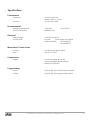
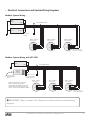
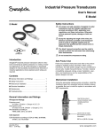
MPX Magnetostrictive Level Sensors User Manual For The MPX-E and MPX-R APG R Doc #9003761 Rev C, 11/14 Table of Contents Introduction................................................................................................................. iii Warranty and Warranty Restrictions..................................................................... iv Chapter 1: Specifications and Options..................................................................... 1 Dimensions.....................................................................................................................................1-2 Specifications.................................................................................................................................... 3 Model Number Configurator........................................................................................................... 4 Electrical Connections and System Wiring Diagrams......................................................... 5-6 Chapter 2: Installation and Removal Procedures and Notes...............................7 Tools Needed...................................................................................................................................... 7 Physical Installation........................................................................................................................ 7 Electrical Installation...................................................................................................................... 8 Removal Instructions...................................................................................................................... 8 Chapter 3: Programming.............................................................................................9 Modbus Programming..................................................................................................................... 9 Modbus Programming with RST-6001 and APG Modbus Software....................................... 9 4-20 mA Programming with RST-4100 and APG Modbus Software..................................... 10 Modbus Register Lists................................................................................................................... 10 Chapter 4: Maintenance............................................................................................ 11 General Care......................................................................................................................................11 Repair and Returns..........................................................................................................................11 Chapter 5: Hazardous Location Installation and Certification.......................... 12 Hazardous Location and Non-Incendive Wiring Diagram..................................................... 12 CSA Certificate of Compliance................................................................................................ 13-16 ii Tel: 1/888/525-7300 • Fax: 1/435/753-7490 • www.apgsensors.com • [email protected] Introduction Thank you for purchasing an MPX series magnetostrictive level sensor from APG. We appreciate your business and your trust. Please take a few minutes to familiarize yourself with your MPX and this manual. The MPX level sensor provides highly accurate and repeatable level readings in a wide variety of liquid level measurement applications. It is certified for installation in hazardous areas in the US and Canada by CSA for Class I, Division 1 & 2 and Class I, Zones 1 and 2 environments. The MPX-R’s large, bouyant, and robust floats allow it to be used in harsh applications where fouling or buildup might otherwise be of concern. The smaller, lighter weight floats of the MPX-E allow it to be used in applications where space is limited. Reading your label Every APG instrument comes with a label that includes the instrument’s model number, part number, and serial number. Please ensure that the part number on your label matches your order. The following electrical ratings and approvals are also listed on the label. Please refer to the Certificate of Compliance at the back of this manual for further details. Electrical ratings Input: 12 - 24 VDC; Output: 4-20 mA / 80 mA Class I, Division 1 & 2, Groups C, and D Ex d IIB Ex nA IIB Class I, Zone 1; AEx d IIB Class I, Zone 2; AEx na IIB Non-Incendive Wiring Requirements: Vmax Ui= 26VDC, Imax Ii = 200ma, Ci = 0nF, Li = 0μH IMPORTANT: MPX level sensor MUST be installed according to drawing 9003468 (Hazardous Installation and Non-Incendive Wiring Drawing) on page 12 to meet listed approvals. Faulty installation will invalidate all safety approvals and ratings. Tel: 1/888/525-7300 • Fax: 1/435/753-7490 • www.apgsensors.com • [email protected] iii Warranty and Warranty Restrictions APG warrants its products to be free from defects of material and workmanship and will, without charge, replace or repair any equipment found defective upon inspection at its factory, provided the equipment has been returned, transportation prepaid, within 24 months from date of shipment from factory. THE FOREGOING WARRANTY IS IN LIEU OF AND EXCLUDES ALL OTHER WARRANTIES NOT EXPRESSLY SET FORTH HEREIN, WHETHER EXPRESSED OR IMPLIED BY OPERATION OF LAW OR OTHERWISE INCLUDING BUT NOT LIMITED TO ANY IMPLIED WARRANTIES OF MERCHANTABILITY OR FITNESS FOR A PARTICULAR PURPOSE. No representation or warranty, express or implied, made by any sales representative, distributor, or other agent or representative of APG which is not specifically set forth herein shall be binding upon APG. APG shall not be liable for any incidental or consequential damages, losses or expenses directly or indirectly arising from the sale, handling, improper application or use of the goods or from any other cause relating thereto and APG’s liability hereunder, in any case, is expressly limited to the repair or replacement (at APG’s option) of goods. Warranty is specifically at the factory. Any on site service will be provided at the sole expense of the Purchaser at standard field service rates. All associated equipment must be protected by properly rated electronic/electrical protection devices. APG shall not be liable for any damage due to improper engineering or installation by the Purchaser or third parties. Proper installation, operation and maintenance of the product becomes the responsibility of the user upon receipt of the product. Returns and allowances must be authorized by APG in advance. APG will assign a Return Material Authorization (RMA) number which must appear on all related papers and the outside of the shipping carton. All returns are subject to the final review by APG. Returns are subject to restocking charges as determined by APG’s “Credit Return Policy”. iv Tel: 1/888/525-7300 • Fax: 1/435/753-7490 • www.apgsensors.com • [email protected] Chapter 1: Specifications and Options • Dimensions MPX-E Sensor and Float Dimensions 5.70” 3/4” NPT 4.25” 5.00” 5.00” Ø 0.27” 7.39” ZERO REFERENCE 2.39” 6” Dead-Band (from reference) Float Options A&B Min. 12” Max. 153” 2.00” C&D Ref. 1.63” 2.06” 1.5” Dead-Band F E (from reference) Ref. 1.38” Ref. 1.87” Ref. 2.20” 1.78” 1.47” Tel: 1/888/525-7300 • Fax: 1/435/753-7490 • www.apgsensors.com • [email protected] 1 MPX-R Sensor and Float Dimensions 5.70” 3/4” NPT 5.00” 4.25” 5.00” Ø 0.27” 6.65” ZERO REFERENCE 1.65” 10” Dead-Band Float Options U&V (from reference) S&T Ref. 2.80” Ref. 5.50” 3.07” Min. 24” Max. 300” 3.03” Y&Z/P&R/L&M Ref. W&X 5.50” 6” Dead-Band 5.00” Ref. (from reference) 5.10” 2 Y&Z P&R L&M 3.08” 2.80” 2.00” Tel: 1/888/525-7300 • Fax: 1/435/753-7490 • www.apgsensors.com • [email protected] • Specifications Performance Resolution Accuracy 4-20 mA: 14 bit DAC Modbus: 0.04 in. (1 mm) ±0.05% of Full Scale Environmental Operating Temperature Enclosure Protection -40 to 85°C NEMA 4X, IP65 (-40 to 185°F) Electrical Supply Voltage 12-24 VDC on sensor Current Draw 4-20 mA: 22 mA single / 44 mA dual Modbus (RS-485): 25 mA (MPX-E) 28 mA (MPX-R) Materials of Construction Housing Stem Cast aluminum, epoxy coated 304 SS or 316L SS Connectivity Output 2 wire, loop-powered 4-20 mA 3 wire, loop-powered dual 4-20 mA Modbus RTU (RS-485) Programming RS-485 4-20 mA Optional RST-6001 USB-to-RS-485 converter Optional RST-4100 programming module Tel: 1/888/525-7300 • Fax: 1/435/753-7490 • www.apgsensors.com • [email protected] 3 • Model Number Configurator Part Number: MPX - _____ _____ - _____ _____ - _____ _____ _____ - L_____ A B C D E F G H A. Stem Type □ E □ R F. Mounting Adjustment □ W □ S 0.5 in. diameter 1 in. diameter B. Output □ 1 □ 2 □ 3 Modbus RTU w/ temperature sensor Single float, 4-20 mA (loop powered, 2 wire) Dual float, 4-20 mA (loop powered, 3 wire) Welded (fixed) Slide with Compression Fitting (adjustable) G. Stem Material □ A □ B 304 SS (MPX-E) 316L SS (MPX-E, MPX-R) H. Total Stem Length in Inches C. Float 1 MPX-E (0.5 in. stem) □ A 2 in. Round 316L SS (0.65 SG) □ B 2 in. Round 316L SS (0.92 SG) □ C 1.38h x 1.63d in. Cylindrical 316L SS (0.61 SG) □ D 1.38h x 1.63d in. Cylindrical 316L SS (0.92 SG) □ E 1.75h x 1.87d Buna-N (0.65 SG) □ F 2.19h x 1.46d in. Oval 316L SS 3A (0.5 SG) □ MPX-E □ MPX-R Min. 12 in. - Max. 153 in. Min. 24 in. - Max. 300 in. Measurable length = stem length - top deadband - bottom deadband: Top Deadband: MPX-E: 6 in.; MPX-R: 10 in. Bottom Deadband: MPX-E: 1.5 in.; MPX-R: 8 in. MPX-R (1 in. stem) □ Z 5.5h x 3d in. Red Polyurethane (0.65 SG) □ Y 5.5h x 3d in. Blue Polyurethane (0.94 SG) □ X 5 in. Round 316L SS (0.52 SG) □ W 5 in. Round 316L SS (0.92 SG) □ V 6h x 3d in. Oval 316L SS (0.58 SG) □ U 6h x 3d in. Oval 316L SS (0.94 SG) □ T 3 in. Round 316L SS (0.60 SG) □ S 3 in. Round 316L SS (0.94 SG) □ R 5.5h x 2.8d in. Red Polyurethane (0.59 SG) 5.5h x 2.8d in. Blue Polyurethane (0.94 SG) □ P □ M 5.5h x 2d in. Red Polyurethane (0.57 SG) □ L 5.5h x 2d in. Blue Polyurethane (0.94 SG) D. Float 2 (optional) Refer to float options in section C or □ NNone E. Mounting Option and Size (ex. F2.5) □ □ □ □ □ 4 F Flat Face ANSI Flange 150# (size-2, 2.5, 3, 4, 5, 6 in.) R Raised Face Flange 150# (size-2, 2.5, 3, 4, 5, 6 in.) S 3A Sanitary ferrule (size-2, 2.5, 3, 4 in.) P NPT Plug (size-1.5, 2, 2.5, 3, 4 in.) NNone Tel: 1/888/525-7300 • Fax: 1/435/753-7490 • www.apgsensors.com • [email protected] • Electrical Connections and System Wiring Diagrams Modbus System Wiring Power Supply +12-24 Vdc Master Device RS-485 A Use Shielded Cable GND RS-485 B 120 Ω terminating resistor MPX-E1 / MPX-R1 series sensor MPX-E1 / MPX-R1 series sensor Sensor 1 Sensor 2 V+ V+ MPX-E1 / MPX-R1 series sensor Sensor 3 V+ B A B A B A GND GND GND 120 Ω terminating resistor at last sensor Modbus System Wiring with RST-6001 Power Supply RST-6001 Modbus Controller USB to computer with APG Modbus software +12-24 Vdc Use Shielded Cable GND A B -5V +5V Equivalent 120 Ω terminating resistor internal to RST-6001 Note: An independent +12-24 Vdc power supply is required when using an RST-6001 Modbus Controller. The RST-6001 can only supply ±5 Vdc, not the +12-24 Vdc required by the MPX. MPX-E1 / MPX-R1 series sensor MPX-E1 / MPX-R1 series sensor MPX-E1 / MPX-R1 series sensor Sensor 1 Sensor 2 Sensor 3 V+ V+ V+ B A B A B A GND GND GND 120 Ω terminating resistor at last sensor IMPORTANT: Refer to Chapter 5 for Hazardous Location and Non-Incendive Wiring diagrams. Tel: 1/888/525-7300 • Fax: 1/435/753-7490 • www.apgsensors.com • [email protected] 5 4-20 mA Loop Wiring 4-20 mA Dual Float Loop Wiring 4-20 mA Single Float Loop Wiring (MPX-E3 and MPX-R3 Series) (MPX-E2 and MPX-R2 Series) + Sensor + − (12-24 Vdc) − Power Source Sensor Power Source (12-24 Vdc) 12-24 Vdc 12-24 Vdc Out 1 Out 2 Out Receiver Input Receiver Com Input 1 Input 2 Com OR + IMPORTANT: Refer to Chapter 5 Sensor for Hazardous Location and Non-Incendive Wiring diagrams. − Power Source (12-24 Vdc) 12-24 Vdc Out 1 Out 2 Receiver 1 Receiver 2 Input Input Com Com 4-20 mA Programming Wiring USB to computer with APG Modbus software Programming configuration is for programming ONLY. After programming, sensor must be reintegrated to 4-20 mA loop for proper system operation. RST-4100 MPX-E2/R2 or MPX-E3/R3 series sensor. Programming Module and APG Modbus software required for programming MPX-E2,3 and MPX-R2,3 series sensors. Out 24V Sensor Note: a minimum of 14 Vdc is required to establish communications with the RST-4100 + 12-24 Vdc Out (1) Out 2 − Power Source (14- 24 Vdc) NOTE: For MPX-E3/R3 series sensors, - Vdc from power source must be connected to Output1 on sensor through a Load Resistor for correct sensor programming. Load Resistor (100 Ω to 700 Ω) 6 Tel: 1/888/525-7300 • Fax: 1/435/753-7490 • www.apgsensors.com • [email protected] Chapter 2: Installation and Removal Procedures and Notes • Tools Needed You will need the following tools to install your MPX level sensor: • Wrench • Physical Installation Notes The MPX should be installed in an area--indoors or outdoors--which meets the following conditions: • Ambient temperature between -40°C and 85°C (-40°F to +185°F) • IEC-664-1 Conductive Pollution Degree 1 or 2 • No corrosive gases such as NH3, SO2, Cl2, etc. • Ample space for maintenance and inspection Additional care must be taken to ensure: • The probe is located away from strong magnetic fields, such as those produced by motors, transformers, solenoid valves, etc. • The medium is free from metallic substances and other foreign matter. • The probe is not exposed to excessive vibration. • The float(s) fit through the mounting hole. If the float(s) does/do not fit, it/they must be mounted on the stem from inside the vessel being monitored. • The float(s) is/are oriented properly on the stem (See Figure 2.1 below). MPX-E floats will be installed by the factory. MPX-R floats are typically installed by customer. Taper UP Figure 2.1 • Physical Installation Instructions • If your sensor’s stem and floats fit through the mounting hole, carefully lower the assembly into the vessel, then secure the sensor to the vessel. • If the floats do not fit, mount them on the stem from inside the vessel being monitored. Then secure the sensor to the vessel. IMPORTANT: Floats must be oriented properly on the stem, or sensor readings will be inaccurate and unreliable. Tel: 1/888/525-7300 • Fax: 1/435/753-7490 • www.apgsensors.com • [email protected] 7 • Electrical Installation • • • • Remove the housing cover of your MPX. Feed system wires into MPX through 3/4” NPT conduit openings. Connect wires to MPX terminals. Replace the housing cover. See Electrical Connections and System Wiring Diagrams (pages 5 and 6) for Modbus and 4-20 mA wiring examples. • Removal Instructions Removing your MPX level sensor from service should be done with care. • If the floats on your sensor fit through the mounting hole, carefully lift the entire sensor assembly out of and away from the vessel. • If the floats on your sensor do not fit through the mounting hole, they will need to be removed from the stem before the sensor can be removed. Be sure to drain the vessel being monitored to allow access to the floats and stem for removal. • Clean the stem and floats of any build up or debris and inspect for damage. • Store your sensor in a dry place, at a temperature between -40° F and 180° F. Chapter 3: Programming • Modbus Programming MPX-E1 and MPX-R1 series sensors use standard Modbus RTU protocol (RS-485). The sensors can only operate as slave devices. Sensor default transmition settings are 9600 Baud, 8 Bits, 1 Stop Bit, No Parity, and require a minimum delay of 300 ms between transactions. See MPX Modbus Register Lists on pages 9 and 10. NOTE: For more information about Modbus RTU, please visit www.modbus.org. • Modbus Programming with RST-6001 and APG Modbus Software APG RST-6001 Modbus Controller can be used in tandem with APG Modbus to program and control up to 20 MPX-E1 or MPX-R1 series sensors. Through APG Modbus, you can monitor the raw readings from the sensor, configure the data for distance, level, volume, or weight, and enter measurements for a strapping chart. See MPX Modbus Register Lists on pages 9 and 10. 8 Tel: 1/888/525-7300 • Fax: 1/435/753-7490 • www.apgsensors.com • [email protected] NOTE: For APG Modbus programming instructions, or to download APG Modbus software, please visit www.apgsensors.com/suppport. • 4-20 mA Programming with RST-4100 and APG Modbus Software APG RST-4100 Programming Module can be used in tandem with APG Modbus to program a single MPX-E2/3 or MPX-R2/3 series sensor. Through APG Modbus, you can configure the 4 mA and 20 mA output setpoints and sensor sensitivity settings. If your monitoring equipment (PLC, etc.) can be configured to interpret the 4-20 mA output(s) of the MPX as volume or weight, then the MPX can be configured accordingly via APG Modbus. However, the RST-4100 is not designed to be used for continuous monitoring of a sensor. After programming your MPX sensor, the RST-4100 must be removed and the wiring reurned to normal. See 4-20 mA Loop Wiring and 4-20 mA Programming Wiring on page 6. • APG Modbus Register Lists Input Registers (0x04) Register 30300 30301 30302 30303-30304 30305-30306 Returned Data Raw Top Float Reading (in mm, unsigned) Raw Bottom Float Reading (in mm, unsigned) Temperature Reading (in 0C, signed) [MPX-R; Optional on MPX-E] Calculated Top Float Reading (in selected Units) Calculated Bottom Float Reading (in selected Units) NOTE: The Calculated Readings will be returned without a decimal place. In order to obtain the true result, the Decimal Place setting must be taken into account. Tel: 1/888/525-7300 • Fax: 1/435/753-7490 • www.apgsensors.com • [email protected] 9 Holding Registers (0x03) Register 40400 40401 40402 40403 40404 40405 40406 40407 40408 40409 40410 40411 40412 40413 40414 40415 40416 40417 40418-40420 40421 40422 40423 40424 40425 40426 40427 40428 40429 40430 40431 40432 40433 40434 40435 40436-40437 40438-40439 40440-40441 40442-40443 40444-40445 10 FunctionValue Range Device Address 1 to 255 Units 1 to 3 Application Type 0-10 Volume Units 0 to 6 Decimal Place 0 to 3 Max Distance 0 to 10364 mm Full Distance 0 to 10364 mm Empty Distance 0 to 10364 mm Sensitivity 0 to 100 Pulses 0 to 20 Blanking 0 to 10364 mm Reserved n/a Averaging 0 to 100 Filter Window 0 to 10364 mm Out of Range Samples 0 to 255 Sample Rate 50 to 1000 msec. Multiplier 1 to 1999 Offset +/- 10364 mm Reserved n/a RTD Offset (0C) -100 to 100 Float Window 0 to 1000 mm Top Float Offset -10364 to 10364 Bottom Float Offset -10364 to 10364 Gain Offset 0 to 255 4 mA Set Point 0 to 10364 mm 20 mA Set Point 0 to 10364 mm 4 mA Calibration 0 to 1000 20 mA Calibration 0 to 1000 Web Alarm 1 Distance Web Alarm 1 Window Web Alarm 1 Type Web Alarm 2 Distance Web Alarm 2 Window Web Alarm 2 Type Parameter 1 Data 0 to 100,000 mm Parameter 2 Data 0 to 100,000 mm Parameter 3 Data 0 to 100,000 mm Parameter 4 Data 0 to 100,000 mm Parameter 5 Data 0 to 100,000 mm Tel: 1/888/525-7300 • Fax: 1/435/753-7490 • www.apgsensors.com • [email protected] Chapter 4: Maintenance • General Care Your MPX level sensor is designed to be low maintenance. However, in general, you should: • Periodically inspect your MPX to ensure the stem and floats are free of any heavy buildup that might impede the movement of the floats. • Ensure the housing cover is snuggly secured. If the cover becomes damaged or is misplaced, order a replacement immediately. • Repair and Returns Should your MPX level sensor require service, please contact the factory via phone, email, or online chat. We will issue you a Return Material Authorization (RMA) number with instructions. • Phone: 888-525-7300 • Email: [email protected] • Online chat at www.apgsensors.com Please have your part number and serial number available. See Warranty and Warranty Restrictions for more information. IMPORTANT: All repairs and adjustments of the MPX level sensor must be made by the factory. Modifing, disassembling, or altering the MPX on site is strictly prohibited. Tel: 1/888/525-7300 • Fax: 1/435/753-7490 • www.apgsensors.com • [email protected] 11 Chapter 5: Hazardous Location Installation and Certification Logan, Utah USA 1025 West 1700 North Automation Products Group, Inc. 888.525.7300 • Hazardous Location and Non-Incendive Wiring Diagram 12 Tel: 1/888/525-7300 • Fax: 1/435/753-7490 • www.apgsensors.com • [email protected] • CSA Certificate of Compliance Certificate of Compliance Certificate: 2397437 Master Contract: 237484 Project: 2397437 Date Issued: May 18, 2011 Issued to: Automation Products Group Inc 1025 West 1700 North Logan, UT 84321 USA Attention: Karl Reid The products listed below are eligible to bear the CSA Mark shown with adjacent indicators 'C' and 'US' for Canada and US or with adjacent indicator 'US' for US only or without either indicator for Canada only. Dennis Jeffrey Issued by: Dennis Jeffrey PRODUCTS CLASS 2258 02 CLASS 2258 82 - PROCESS CONTROL EQUIPMENT - For Hazardous Locations - PROCESS CONTROL EQUIPMENT - For Hazardous Locations Certified to US Standards Class I, Division 1 & 2, Groups C, and D Ex d IIB Ex nA IIB Class I, Zone 1; AEx d IIB Class I, Zone 2; AEx nA IIB Float Level Sensors, model MPX-ab-cd-efg-hhh, rated 12 - 24 Vdc, 80mA, or rated 12 to 24 Vdc, 4-20mA; operating ambient Ta is 85°C; Temperature Code T4; Ingress protection IP65; Field wiring is non-incendive when installed per drawing 9003468. DQD 507 Rev. 2009-09-01 Page: 1 Tel: 1/888/525-7300 • Fax: 1/435/753-7490 • www.apgsensors.com • [email protected] 13 Certificate: 2397437 Master Contract: 237484 Project: 2397437 Date Issued: May 18, 2011 Notes: • The model code breakdown is as follows: a= E or R; b= 1, 2 or 3; c= A, B, C, D, E, F, Z, or Y; d= N, B, D, or Y; e= F, R, P, N, or O; f= W or S; g= A or B; and hhh= 12–153 for the 1/2" stem or 48–300 for the 1" stem. • The equipment is intended to be installed as required by the applicable electrical code (CEC, NEC) and as specified by the manufacturers Installation Instructions. • The installation will be inspected by the authority with jurisdiction in the area where installed. APPLICABLE REQUIREMENTS CSA C22.2 No 0-10 CSA C22.2 No 30-M1986 (R 2007) CSA C22.2 No 142-M1987 (R 2009) CSA C22.2 No 213-M1987 (R 2008) CSA C22.2 No 60079-0-07 CSA C22.2 No 60079-1-07 CSA E60079-15-02 (R 2006) UL 508 UL 1203 ANSI/ISA-12.12.01-2007 General Requirements – Canadian Electrical Code, Part II – Tenth Edition Explosion-Proof Enclosures for Use in Class I Hazardous Locations Industrial Products – Third Edition Process Control Equipment Industrial Products – Third Edition Non-incendive Electrical Equipment for Use in Class I, Division 2 Hazardous Locations Industrial Products – First Edition Electrical apparatus for explosive gas atmospheres – Part 0: General requirements – First Edition Electrical apparatus for explosive gas atmospheres – Part 1: Flameproof enclosures "d" – First Edition Electrical Apparatus for Explosive Gas Atmospheres – Part 15: Type of Protection "n" – Second Edition Industrial Control Equipment - Seventeenth Edition; Reprint with Revisions Through and Including April 15, 2010 Explosion-Proof and Dust-Ignition-Proof Electrical Equipment for Use in Hazardous (Classified) Locations - Fourth Edition; Reprint with Revisions through and Including October 28, 2009 Nonincendive Electrical Equipment for Use in Class I and II, Division 2 and Class III, Divisions 1 and 2 Hazardous (Classified) Locations MARKINGS The following markings are provided on a UL Recognized (PGJI2) adhesive nameplate manufactured by Datamax, type FantaStock-HCW, printed with a resin ribbon manufactured by Datamax, type Greatribbon SDR or SDR-5, which is suitable for indoor/outdoor use on polyurethane paint coatings, at a maximum service temperature of 135°C or higher. Alternatively a screw or rivet secured metal nameplate or other permanent DQD 507 Rev. 2009-09-01 14 Page: 2 Tel: 1/888/525-7300 • Fax: 1/435/753-7490 • www.apgsensors.com • [email protected] Certificate: 2397437 Master Contract: 237484 Project: 2397437 Date Issued: May 18, 2011 manner can be used. The nameplate is affixed to the top of the enclosure. Labels, if shown in the report, may vary slightly in layout, provided that the required information continues to be shown. The following markings appear on each product where applicable: • Manufacturer’s name: "Automation Products Group", or CSA Master Contract Number “237484”, adjacent to the CSA Mark in lieu of manufacturer’s name. • Model number: As specified in the PRODUCTS section, above. • Electrical ratings: As specified in the PRODUCTS section, above. • Ambient temperature rating: As specified in the PRODUCTS section, above. • Manufacturing date in MMYY format, or serial number, traceable to month of manufacture. • Enclosure ratings: As specified in the PRODUCTS section, above. • The CSA Mark with or without “C” and “US” indicators, as shown on the Certificate of Conformity. • Hazardous Location designation: As specified in the PRODUCTS section, above (may be abbreviated). • Temperature code: As specified in the PRODUCTS section, above. • The name or mark of the certificate issuer and the certificate reference in the following form: the last two figures of the year of the certificate followed by the serial number of the certificate in that year. • The following words: • “OPEN CIRCUIT BEFORE REMOVING COVER” or "KEEP COVER TIGHT WHILE CIRCUITS ARE ALIVE”. • “WARNING – EXPLOSION HAZARD - Substitution of components may impair suitability for Class I, Division 2.” • “WARNING – EXPLOSION HAZARD – Do not connect while circuit is live unless area is known to be nonhazardous.” • “Install per drawing 9003468 (as appropriate for nonincendive field wiring only).” An installation manual or data sheet shall be supplied with each unit, containing the following minimum marking information: General: Technical specifications, instructions for use and details of where technical assistance may be obtained if required. Equipment Ratings: This includes equipment supply, description of I/O connections, duty cycle and operating environmental conditions. • Pollution degree 2; • Measurement category II; • Altitude 2000 m; • Humidity 0 to 100%; • Electrical supply DC, • Indoor and outdoor use statement; • Temperature - 40°C to 85°C; Equipment Installation: This includes instructions for assembly and mounting, location requirements, details for special services (cooling supply, etc.) as applicable. DQD 507 Rev. 2009-09-01 Page: 3 Tel: 1/888/525-7300 • Fax: 1/435/753-7490 • www.apgsensors.com • [email protected] 15 Certificate: 2397437 Master Contract: 237484 Project: 2397437 Date Issued: May 18, 2011 PERMANENTLY CONNECTED EQUIPMENT requires the special considerations to satisfy the CEC and the Canadian deviations in the standard, including overcurrent and fault protection as required. Equipment Operation: This includes explanations of operating controls and warning symbols used, and instructions for interconnection, replacement of consumables (e.g. paper) and cleaning as required. Equipment Maintenance: This includes instructions for preventative maintenance, inspection and cleaning, replacement of parts, etc. Note - Jurisdictions in Canada may require these markings to also be provided in French language. It is the responsibility of the manufacturer to provide bilingual marking, where applicable, in accordance with the requirements of the Provincial Regulatory Authorities. It is the responsibility of the manufacturer to determine this requirement and have bilingual wording added to the "Markings". DQD 507 Rev. 2009-09-01 16 Page: 4 Tel: 1/888/525-7300 • Fax: 1/435/753-7490 • www.apgsensors.com • [email protected] APG R Automation Products Group, Inc. Tel: 1/888/525-7300 • Fax: 1/435/753-7490 • www.apgsensors.com • [email protected]