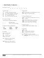
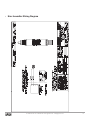
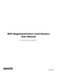
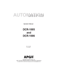
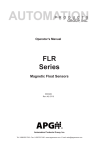
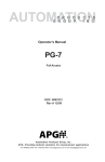
1
PT-500 Analog Output Series User Manual 4-20 mA, 0-5 VDC, 0-10 VDC, mV/V APG R Doc #9002823 Rev C5, 05/15 Table of Contents Introduction................................................................................................................. iii Warranty and Warranty Restrictions..................................................................... iv Chapter 1: Specifications and Options..................................................................... 1 Dimensions.........................................................................................................................................1 Specifications.................................................................................................................................... 2 Model Number Configurator........................................................................................................... 3 Electrical Pinout Table and Supply Power Table....................................................................... 4 Chapter 2: Installation and Removal Procedures and Notes...............................4 Tools Needed...................................................................................................................................... 4 Mounting Instructions.................................................................................................................... 4 Electrical Installation...................................................................................................................... 5 Removal Instructions...................................................................................................................... 5 Chapter 3: Maintenance..............................................................................................5 General Care....................................................................................................................................... 5 Zero Adjust......................................................................................................................................... 6 Vent Tube Drying.............................................................................................................................. 6 Repair and Returns........................................................................................................................... 7 Chapter 4: Hazardous Location Installation and Certification...........................8 Intrinsically Safe Wiring Diagram................................................................................................ 8 Non-Incendive Wiring Diagrams................................................................................................... 9 CSA Certificate of Compliance................................................................................................10-13 NOTE: Wiring and CSA Certification information in this User Manual is specific to the Analog Output Series of the PT-500. If you have a Modbus Series sensor, please consult the factory at 1-888-525-7300, or our website at www.apgsensors.com/support, for the appropriate manual for your sensor. ii Tel: 1/888/525-7300 • Fax: 1/435/753-7490 • www.apgsensors.com • [email protected] Introduction Thank you for purchasing a PT-500 Analog Output series submersible pressure transmitter from APG. We appreciate your business! Please take a few minutes to familiarize yourself with your PT-500 and this manual. PT-500 submersible pressure transmitters offer reliability in harsh industrial conditions and hazardous locations. The 4-20 mA model is certified intrinsically safe for hazardous areas in the US and Canada by CSA for Class I, Division 2, Groups C and D, Class I, Zone 2, Group IIB, and Class I, Division 1, Groups C and D, Class I, Zone 0, Group IIB environments. The small size, integrated electronics, wide operating temperature range, and durability make the PT-500 the perfect instrument for static and dynamic pressure measurement. Reading your label Every APG instrument comes with a label that includes the instrument’s model number, part number, serial number, and a wiring pinout table. Please ensure that the part number and pinout table on your label match your order. The following electrical ratings and approvals are also listed on the label. Please refer to the Certificate of Compliance at the back of this manual for further details. Electrical ratings Input: 10 to 28 Volts DC; Output: 4-20 mA Exia Class I, Division 2; Groups C, D T4 Class I, Zone 2, Group IIB AEx nC IIB T4: Ta: -40°C to 85°C Ex nL IIB T4: Ta: -40°C to 85°C Maximum Working Pressure: 10,000 PSI Vmax Ui= 28VDC, Imax Ii = 110mA, Pmax Pi = 0.77W, Ci = 0μF, Li = 0μH Install in accordance with drawing 9002803, sheet 2 (page 9). Input: 9 to 28 Volts DC; Output: 4-20mA Exia Class I, Division 1; Groups C, D T4 Class I, Zone 0, Group IIB AEx ia IIB T4: Ta: -40°C to 85°C Ex ia IIB T4: Ta: -40°C to 85°C Maxium Working Pressure: 10,000 PSI Vmax Ui= 28VDC, Imax Ii = 110mA, Pmax Pi = 0.77W, Ci = 0.042μF, Li = 0.320μH Install in accordance with drawing 9002803, sheet 1 (page 8). IMPORTANT: Your 4-20 mA PT-500 MUST be installed according to drawing 9002803 (Intrinsically Safe Wiring Diagram or Non-Incendive Wiring Diagram) as indicated above to meet listed approvals. Faulty installation will invalidate all safety approvals and ratings. Tel: 1/888/525-7300 • Fax: 1/435/753-7490 • www.apgsensors.com • [email protected] iii Warranty and Warranty Restrictions APG warrants its products to be free from defects of material and workmanship and will, without charge, replace or repair any equipment found defective upon inspection at its factory, provided the equipment has been returned, transportation prepaid, within 24 months from date of shipment from factory. THE FOREGOING WARRANTY IS IN LIEU OF AND EXCLUDES ALL OTHER WARRANTIES NOT EXPRESSLY SET FORTH HEREIN, WHETHER EXPRESSED OR IMPLIED BY OPERATION OF LAW OR OTHERWISE INCLUDING BUT NOT LIMITED TO ANY IMPLIED WARRANTIES OF MERCHANTABILITY OR FITNESS FOR A PARTICULAR PURPOSE. No representation or warranty, express or implied, made by any sales representative, distributor, or other agent or representative of APG which is not specifically set forth herein shall be binding upon APG. APG shall not be liable for any incidental or consequential damages, losses or expenses directly or indirectly arising from the sale, handling, improper application or use of the goods or from any other cause relating thereto and APG’s liability hereunder, in any case, is expressly limited to the repair or replacement (at APG’s option) of goods. Warranty is specifically at the factory. Any on site service will be provided at the sole expense of the Purchaser at standard field service rates. All associated equipment must be protected by properly rated electronic/electrical protection devices. APG shall not be liable for any damage due to improper engineering or installation by the Purchaser or third parties. Proper installation, operation and maintenance of the product becomes the responsibility of the user upon receipt of the product. Returns and allowances must be authorized by APG in advance. APG will assign a Return Material Authorization (RMA) number which must appear on all related papers and the outside of the shipping carton. All returns are subject to the final review by APG. Returns are subject to restocking charges as determined by APG’s “Credit Return Policy”. iv Tel: 1/888/525-7300 • Fax: 1/435/753-7490 • www.apgsensors.com • [email protected] Chapter 1: Specifications and Options • Dimensions 7.14" [181.3mm] 7.40” [187.9mm] NON-REMOVABLE SENSOR CAGE ASSEMBLY REMOVABLE SENSOR CAGE ASSEMBLY 2.00" [50.8] 2.24” [56.9mm] ø3.50" ø3.50” [88.9mm] [88.9mm] PT-500 with Reusable Cage PT-500 with Welded Anti-snag Cage 6.44" [163.5mm] 5.29" [134.4mm] PROTECTIVE CONE ø.188 THRU 1 1/2" SANITARY FITTING ø1.00" [25.4mm] ø1.98" [50.3mm] PT-500 with Tri-clover Sanitary Fitting PT-500 with Removable Plastic Nose Cone Tel: 1/888/525-7300 • Fax: 1/435/753-7490 • www.apgsensors.com • [email protected] 1 • Specifications Performance Pressure Ranges Analog Outputs Over Pressure Burst Pressure 1 Year Stability 0 to 300 PSIG 4-20mA, 0-5VDC, 0-10VDC, mV/V 2X FSO 3.0X FSO 0.75% FSO Accuracy Linearity, Hystereses & Repeatability Thermal Zero Shift @ 70 °F Thermal Span Shift @ 70 °F ±0.25% of Full Scale (BFSL) up to ±0.1% of Full Scale ±0.045% FSO/°C (±0.025% FSO/°F) ±0.045% FSO/°C (±0.025% FSO/°F) Environmental Operating Temperature Compensated Temperature Maximum Submersible Depth -40 to 85°C (-40 to 185°F) -17 to 54°C (0 to 130°F) 462.2 ft / 140.88 m / 300 psig Electrical Supply Voltage (at sensor) Output Signal @ 21°C Protection Load Limitation Startup Time Current Draw 4-20 mA: 9-28 VDC 0-10 VDC: 14-28 VDC 0-5 VDC: 9-28 VDC mV/V: 10 VDC* 3-30 mA max. Reverse Polarity and Surge (per IEC 61000-4-5) R(max) = ((Vs-12V)/0.02A)-(0.042Ω per ft. of cable) 4-20 mA: 100 ms 0-10 VDC: 300 ms 0-5 VDC: 300 ms 4-20 mA: 3-30 mA 0-10 VDC: 3 mA 0-5 VDC: 3 mA Materials of Construction Wetted Materials Anti-snag Cage Cable Protective Nose Cone 316L Stainless Steel 316L Stainless Steel Urethane, PVC, or Hytrel Delrin Mechanical Pressure Connection Cable Tensile Strength See model number configurator for complete list Up to 200 pounds Patents US Patent No. 7,787,330 *mV/V output is calibrated to 10 VDC input. 2 Tel: 1/888/525-7300 • Fax: 1/435/753-7490 • www.apgsensors.com • [email protected] • Model Number Configurator Part Number: PT-500_____ - _____ - _____ - _____ - _____ - _____ - _____ - _____ A B C D E F G H A. Cable Type E. Overmold □ -▲ Urethane - Blue (with vent tube) □ A PVC - Black (no vent tube - sealed unit) □B Hytrel .31” Ø - Black (with vent tube) □C PVC - Black (with vent tube) □ D Hytrel .25” Ø - Black (with vent tube) □ E0▲ No overmold for 1/2” NPTM fitting for conduit □ E37 Pigtail with overmolded cable B. Pressure Range □ Specify range in desired unit of measure __________ Max Water Depth 462.2 ft. (140.9 m), 300 psig C. Standard Units of Measure □ PSI □ FTH2O □ INWC □ INH2O □ MMH2O □ FWC F. Process Connection □ P1▲ □ P5 □ P37 □ P38 □ P39 1/2” NPTM with removable plastic nose cone 1/4” NPTF Welded Cage (anti-snag 1 piece fitting) 1-1/2” tri-clover with 3/4” diaphragm Reusable Cage (includes P38 fitting) G. Cable Length □ (specify length of cable needed in feet) H. Accuracy □ N0▲ ±0.25% □ N1 ±0.25% with NIST certification □ N2 ±0.1% with NIST certification D. Output □ L1▲ □ L3 □ L9 □ L10 4-20 mA, 2-wire 0-5V, 4-wire* 10 mV/V, 4-wire* 0-10V, 4-wire* □ L5 □ L31 Modbus RTU, 4-wire RS-485* Pressure reading only Note: ▲Indicates this option is standard. Note: *Indicates this option does not yet have CSA Approvals. Modbus RTU, 4-wire RS-485 * Level calculations, tank volume Tel: 1/888/525-7300 • Fax: 1/435/753-7490 • www.apgsensors.com • [email protected] 3 • Electrical Pinout Table and Supply Power Table Pigtail PT-500 Analog Output Series Pin Out Table 4-20 mA Voltage Red + Power/Signal + Power Black - Power/Signal - Power Green - + Out White - - Out Shield Case Gnd Case Gnd PT-500 Analog Output Series Supply Power Table Power Supply 4-20 mA 0-5 VDC 0-10 VDC mV/V 9-28 VDC 9-28 VDC 14-28 VDC 10 VDC* * mV/V output calibrated to 10 VDC input Chapter 2: Installation and Removal Procedures and Notes • Tools Needed • Wrench sized appropriately for your PT-500’s process or conduit connection. • Thread tape or sealant compound for threaded connections. • Mounting Instructions Your PT-500 can be mounted in three ways: via NPT process connection, free-hanging suspension, or conduit mounted. Mounting your pressure transducer is easy if you follow a few simple steps: • Never over-tighten the sensor. This can compress the diaphragm, changing how it reacts to pressure. In all cases, tighten the sensor as little as possible to create an adequate seal. On straight threads, tighten only until you feel the o-ring compress - making sure you don’t damage or extrude the o-ring. • Always use thread tape or sealant compound on tapered threads. Wrap thread tape in the opposite direction of the threads so it does not unravel as you screw the sensor into place. Unraveling can cause uneven distribution and seal failure. For straight threads use an o-ring. • Always start screwing in your sensor by hand to avoid cross-threading. Thread failure can be a problem if you damage threads by over-tightening them or by crossing threads. • For suspension mounting the PT-500, drill a 3/16” hole into the 1/2” NPTF to 1/2” NPTF hex coupler (P/N 511414) and secure it to the 1/2” NPTM coupler fitting of the PT-500. Attach a .060” diameter 316L SS cable of desired length to the hex coupler and secure the steel cable according to your application requirements. • Electrical Installation • Attach the wires of your PT-500 to your control system according to the pinout table above. 4 Tel: 1/888/525-7300 • Fax: 1/435/753-7490 • www.apgsensors.com • [email protected] NOTE: If your PT-500 has a vent tube, do not seal, cover, or close the vent tube with anything other than an APG-provided venting cap or desiccant drying cartridge (See Figure 4.1 and 4.2). Unapproved seals or covers will prevent proper sensor operation. • Removal Instructions Removing your PT-500 from service must be done with care. It’s easy to create an unsafe situation, or damage your sensor, if you are not careful to follow these guidelines: • For sensors installed via NPT process connection, make sure the pressure is completely removed from the line or vessel. Follow any and all procedures for safely isolating any media contained inside the line or vessel. • Remove the sensor with an appropriately sized wrench (per your process connection). • For suspended sensors, retrieve the sensor from the vessel. Follow any and all procedures for safely isolating any media contained inside the line or vessel. • Carefully clean the sensor’s fitting and diaphragm of any debris (see General Care) and inspect for damage. • Store your sensor in a dry place, at a temperature between -40° F and 180° F. DANGER: Removing your process connected PT-500 Pressure Transmitter while there is still pressure in the line could result in injury or death. Chapter 3: Maintenance • General Care Your PT-500 series pressure transmitter is very low maintenance and will need little care as long as it is installed correctly. However, in general, you should: • For process connected sensors, keep the transmitter and the area around it generally clean. • Avoid applications for which the transmitter was not designed, such as extreme temperatures, contact with incompatible corrosive chemicals, or other damaging environments. • Inspect the threads whenever you remove the transmitter from duty or change its location. • Avoid touching the diaphragm. Contact with the diaphragm, especially with a tool, could permanently shift the output and ruin accuracy. • Clean the diaphragm or the diaphragm bore only with extreme care. If using a tool is required, make sure it does not touch the diaphragm. IMPORTANT: Any contact with the diaphragm can permanently damage the sensor. Use extreme caution. Tel: 1/888/525-7300 • Fax: 1/435/753-7490 • www.apgsensors.com • [email protected] 5 • Zero Adjust (4-20 mA, 0-5 VDC, and 0-10 VDC only) The zero output (4mA, or 0 VDC) can be adjusted by holding a magnet perpendicular to the can, approximately 1-1/2” from the top or bottom of the can. Holding the magnet close to the top of the can increases the output (See Figure 3.1). Holding the magnet close to the bottom of the can decreases the output (See Figure 3.2). If the zero output values do not change right away, hold the magnet in place near the top of the can until the values change, for up to two minutes. If there is no change, repeat the procedure near the bottom of the can. If there is still no change, consult the factory. Unvented PT-500A transmitters do not automatically adjust to changes in barometric pressure. We recommend that PT-500A transmitters be zeroed upon receipt, and after major weather events. Figure 3.1 Figure 3.2 NOTE: Span calibration must be done at the factory for all analog models. • Vent Tube Drying Condensation in the vent tube can damage the electronics in your sensor, resulting in unreliable readings. APG offers two methods of preventing vent tube condensation: a venting cap, and a desiccant drying cartridge. The venting cap is a PVC tube with a hydrophobic patch that allows moisture to pass out of the tube without allowing water in (See Figure 3.3). The cap is sealed by an o-ring, and is easily installed in the field. The desiccant drying cartridge with vent tube adapter absorbs any moisture in the vent tube to keep vapor from condensing (See Figure 3.4). The installation of the desiccant drying cartridge is quick and easy. Common installation methods are cable tie, Velcro, and cable clamps. 6 Tel: 1/888/525-7300 • Fax: 1/435/753-7490 • www.apgsensors.com • [email protected] Figure 3.3 Figure 3.4 NOTE: Desiccant crystals change from blue to pink as they become saturated. Cartridge must be replaced when all crystals have saturated. IMPORTANT: Do NOT use desiccant cartridge in the presence of vapors or liquids containing phosphate esters, synthetic lubricants, hydrocarbon solvents, methanol, acetone, lacquer solvents, or other organics. • Repair and Returns Should your PT-500 series pressure transmitter require service, please contact the factory via phone, email, or online chat. We will issue you a Return Material Authorization (RMA) number with instructions. • Phone: 888-525-7300 • Email: [email protected] • Online chat at www.apgsensors.com Please have your PT-500’s part number and serial number available. See Warranty and Warranty Restrictions for more information. Tel: 1/888/525-7300 • Fax: 1/435/753-7490 • www.apgsensors.com • [email protected] 7 Chapter 4: Hazardous Location Installation and Certification • Intrinsically Safe Wiring Diagram 8 Tel: 1/888/525-7300 • Fax: 1/435/753-7490 • www.apgsensors.com • [email protected] • Non-Incendive Wiring Diagram Tel: 1/888/525-7300 • Fax: 1/435/753-7490 • www.apgsensors.com • [email protected] 9 • CSA Certificate of Compliance Certificate of Compliance Certificate: 1984045 Master Contract: 237484 Project: 2587208 Date Issued: December 17, 2012 Issued to: Automation Products Group Inc 1025 West 1700 North Logan, UT 84321 USA Attention: Karl Reid The products listed below are eligible to bear the CSA Mark shown with adjacent indicators 'C' and 'US' for Canada and US or with adjacent indicator 'US' for US only or without either indicator for Canada only. Eshwar Kashyap Issued by: Eshwar Kashyap PRODUCTS CLASS 2258 03 CLASS 2258 83 - PROCESS CONTROL EQUIPMENT - Intrinsically Safe and Non Incendive Systems - For Hazardous Locations - PROCESS CONTROL EQUIPMENT-Intrinsically Safe and NonIncendive - Systems-For Hazardous Locations-Certified to U.S. Standards Class I, Div. 2, Groups C and D Class I, Zone 2, Group IIB Ex nL IIB T4; Ta: -40°C ... +85°C AEx nC IIB T4; Ta: -40°C ... +85°C • Model PT-400-L1xxxx Pressure Transmitter. Rated 9-28VDC, 4-20mA. Maximum Ambient 85° C; Temperature Code T4; Maximum Working Pressure 10,000 PSI. Enclosure type: IP65. Installed as per Drawing 9002794. Non-Incendive with the following Entity Parameters: Vmax, Ui = 28V Imax, Ii = 110mA Pmax, Pi = 0.77W DQD 507 Rev. 2012-05-22 10 Page: 1 Tel: 1/888/525-7300 • Fax: 1/435/753-7490 • www.apgsensors.com • [email protected] Certificate: 1984045 Master Contract: 237484 Project: 2587208 Date Issued: December 17, 2012 Ci = 0.055µF Li = 7.95µH • Model PT-400-L3/L10xxxx Pressure Transmitter. Rated 9-28VDC, 4-20mA or 0-5V, 20mA or 0-10V, 20mA; Maximum Ambient 85° C; Temperature Code T4; Maximum Working Pressure 10,000 PSI. Installed as per Drawing 9002794. Non-Incendive with the following Entity Parameters: Vmax, Ui = 28V Imax, Ii = 110mA Pmax, Pi = 0.77W Ci = 0µF Li = 0µH • Model PT-500-xxxx Pressure Transmitter, Rated 10-28VDC, 4-20mA; Maximum Ambient 85° C; Temperature Code T4; Maximum Working Pressure 10,000 PSI; Non-Incendive with the following Entity Parameters: Vmax, Ui = 28V Imax, Ii = 110mA Pmax, Pi = 0.77W Ci = 0µF Li = 0µH Notes for Models PT-400, PT-500: 1. The "x" in the Model designations may be any alpha-numeric character, to denote minor mechanical options, not affecting safety. 2. These devices must be connected to a suitably certified and approved apparatus that provides non-incendive outputs either equal to or less than those as indicated by the applicable control drawings. This certified apparatus must be located in a safe area. CLASS 2258 04 - Process Control Equipment - Intrinsically Safe, Entity - For Hazardous Locations DQD 507 Rev. 2012-05-22 Page: 2 Tel: 1/888/525-7300 • Fax: 1/435/753-7490 • www.apgsensors.com • [email protected] 11 Certificate: 1984045 Master Contract: 237484 Project: 2587208 Date Issued: December 17, 2012 CLASS 2258 84 - Process Control Equipment - Intrinsically Safe, Entity - For Hazardous Locations - Certified to US Standards Class I, Div. 1, Groups C, D Class I, Zone 0, Group IIB Ex ia IIB T4; Ta: -40°C ... +85°C AEx ia IIB T4; Ta: -40°C ... +85°C • Model PT-400-L1xxxx Pressure Transmitter. Rated 9-28VDC, 4-20mA. Maximum Working Pressure: 10,000 PSI. Installed as per Drawing 9002794. Ambient Range: -40°C to +85°C. Enclosure type: IP65. Intrinsically safe with the following entity parameters: Vmax, Ui = 28V Imax, Ii = 110mA Pmax, Pi = 0.77W Ci = 0.055µF Li = 7.95µH • Model PT-500-xxxx Pressure Transmitter; Maximum Ambient 85° C; Temperature Code T4; Maximum Working Pressure 10,000 PSI; Entity parameters as follows: Vmax, Ui = 28V Imax, Ii = 110mA Pmax, Pi = 0.77W Ci = 0.042µF Li = 0.320µH Notes for Models PT-400, PT-500: 1. The "x" in the Model designations may be any alpha-numeric character, to denote minor mechanical options, not affecting safety. 2. These devices must be connected to a NRTL approved safety barrier (located in a safe area). DQD 507 Rev. 2012-05-22 12 Page: 3 Tel: 1/888/525-7300 • Fax: 1/435/753-7490 • www.apgsensors.com • [email protected] Certificate: 1984045 Master Contract: 237484 Project: 2587208 Date Issued: December 17, 2012 APPLICABLE REQUIREMENTS C22.2 No 0 - M1991 C22.2 No 0.4 - M2004 C22.2 No 142 - M1987 C22.2 No 157 - M1992 C22.2 No 213 - M1987 CAN/CSA-C22.2 No. 60079-0:11 CAN/CSA-C22.2 No. 60079-11:11 CAN/CSA-C22.2 No. 60079-15:12 CAN/CSA-C22.2 No. 60529:05 UL 508, 17th Edition UL 913, 7Th Edition ANSI/ISA-12.12.01-2007 ANSI/UL 60079-0:09 ANSI/UL 60079-11:09 ANSI/UL 60079-15:09 ANSI/IEC 60529:2004 DQD 507 Rev. 2012-05-22 General Requirements - Canadian Electrical Code Part II. Bonding and Grounding of Electrical Equipment (Protective Grounding). Process Control Equipment. Intrinsically Safe and Non-Incendive Equipment for Use in Hazardous Locations. Non-Incendive Electrical Equipment for Use in Class I, Division 2 Hazardous Locations. Explosive Atmospheres - Part 0: Equipment - General requirements Explosive Atmospheres – Part 11: Equipment protection by intrinsic safety "i" Electrical apparatus for explosive gas atmospheres - Part 15: Construction, test and marking of type of protection “n” electrical apparatus Degrees of protection provided by enclosures (IP Code) Industrial Control Equipment. Intrinsically Safe Apparatus and Associated Apparatus for use in Class I, II, III, Division 1, Hazardous (Classified) Locations. Nonincendive Electrical Equipment for Use in Class I and II, Division 2 and Class III, Divisions 1 and 2 Hazardous (Classified) Locations Electrical Apparatus for Explosive Gas Atmospheres Part 0: General Requirements Electrical apparatus for Explosive Gas Atmospheres Part 11: Intrinsic Safety “i” Electrical apparatus for Explosive Gas Atmospheres Part 15: Type of Protection “n” Degrees of Protection Provided by Enclosures (IP Code) Page: 4 Tel: 1/888/525-7300 • Fax: 1/435/753-7490 • www.apgsensors.com • [email protected] 13 APG R Automation Products Group, Inc. Tel: 1/888/525-7300 • Fax: 1/435/753-7490 • www.apgsensors.com • [email protected]