1
Right choice for ultimate yield
LSIS strives to maximize customers' profit in gratitude of choosing us for your partner.
Programmable Logic Controller
XGB Cnet I/F
XGT Series
User’s Manual
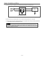
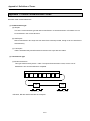
Main Unit
Built-in Cnet
XBM
XBC/XEC
XBC/XEC
XBC/XEC
XBC/XEC
S TYPE
E TYPE
S TYPE
SU TYPE
H TYPE
Cnet I/F XBL-C41A
module XBL-C21A
Read
this manual carefully before
installing, wiring, operating, servicing
or inspecting this equipment.
Keep
this manual within easy reach
for quick reference.
http://www.lsis.com
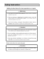
Safety Instruction
Before using the product …
For your safety and effective operation, please read the safety instructions
thoroughly before using the product.
► Safety Instructions should always be observed in order to prevent accident
or risk by using the product properly and safely.
► Precautious measures can be categorized as “Warning” and “Caution”, and
each of the meanings is as follows.
Warning
This symbol indicates the possibility of serious injury
or death if some applicable instruction is violated
Caution
This symbol indicates the possibility of severe or
slight injury, and damages in products if some
applicable instruction is violated
Moreover, even classified events under its caution category may develop into
serious accidents depending on situations. Therefore we strongly advise users
to observe all precautions in a proper way just like warnings.
► The marks displayed on the product and in the user’s manual have the
following meanings.
Be careful! Danger may be expected.
Be careful! Electric shock may occur.
After reading this user’s manual, it should be stored in a place that is visible
to product users.
Safety Instruction
Safety Instructions when designing
Warning
Please, install protection circuit on the exterior of PLC to protect
the whole control system from any error in external power or PLC
module. Any abnormal output or operation may cause serious problem
in safety of the whole system.
- Install applicable protection unit on the exterior of PLC to protect
the system from physical damage such as emergent stop switch,
protection circuit, the upper/lowest limit switch, forward/reverse
operation interlock circuit, etc.
- If any system error (watch-dog timer error, module installation error,
etc.) is detected during CPU operation in PLC, the whole output is
designed to be turned off and stopped for system safety. However,
in case CPU error if caused on output device itself such as relay or
TR can not be detected, the output may be kept on, which may
cause serious problems. Thus, you are recommended to install an
addition circuit to monitor the output status.
Never connect the overload than rated to the output module nor
allow the output circuit to have a short circuit, which may cause a
fire.
Never let the external power of the output circuit be designed to
be On earlier than PLC power, which may cause abnormal output or
operation.
In case of data exchange between computer or other external
equipment and PLC through communication or any operation of
PLC (e.g. operation mode change), please install interlock in the
sequence program to protect the system from any error. If not, it
may cause abnormal output or operation.
Safety Instruction
Safety Instructions when designing
Caution
I/O signal or communication line shall be wired at least 100mm
away from a high-voltage cable or power line. If not, it may cause
abnormal output or operation.
Safety Instructions when designing
Caution
Use PLC only in the environment specified in PLC manual or
general standard of data sheet. If not, electric shock, fire, abnormal
operation of the product or flames may be caused.
Before installing the module, be sure PLC power is off. If not,
electric shock or damage on the product may be caused.
Be sure that each module of PLC is correctly secured. If the
product is installed loosely or incorrectly, abnormal operation, error or
dropping may be caused.
Be sure that I/O or extension connecter is correctly secured. If
not, electric shock, fire or abnormal operation may be caused.
If lots of vibration is expected in the installation environment,
don’t let PLC directly vibrated. Electric shock, fire or abnormal
operation may be caused.
Don’t let any metallic foreign materials inside the product, which
may cause electric shock, fire or abnormal operation..
Safety Instruction
Safety Instructions when wiring
Warning
Prior to wiring, be sure that power of PLC and external power is
turned off. If not, electric shock or damage on the product may be
caused.
Before PLC system is powered on, be sure that all the covers of
the terminal are securely closed. If not, electric shock may be caused
Caution
Let the wiring installed correctly after checking the voltage rated
of each product and the arrangement of terminals. If not, fire,
electric shock or abnormal operation may be caused.
Secure the screws of terminals tightly with specified torque when
wiring. If the screws of terminals get loose, short circuit, fire or abnormal
operation may be caused.
*
Surely use the ground wire of Class 3 for FG terminals, which is
exclusively used for PLC. If the terminals not grounded correctly,
abnormal operation may be caused.
Don’t let any foreign materials such as wiring waste inside the
module while wiring, which may cause fire, damage on the product
or abnormal operation.
Safety Instruction
Safety Instructions for test-operation or repair
Warning
Don’t touch the terminal when powered. Electric shock or abnormal
operation may occur.
Prior to cleaning or tightening the terminal screws, let all the
external power off including PLC power. If not, electric shock or
abnormal operation may occur.
Don’t let the battery recharged, disassembled, heated, short or
soldered. Heat, explosion or ignition may cause injuries or fire.
Caution
Don’t remove PCB from the module case nor remodel the module.
Fire, electric shock or abnormal operation may occur.
Prior to installing or disassembling the module, let all the external
power off including PLC power. If not, electric shock or abnormal
operation may occur.
Keep any wireless installations or cell phone at least 30cm away
from PLC. If not, abnormal operation may be caused.
Safety Instructions for waste disposal
Caution
Product or battery waste shall be processed as industrial waste.
The waste may discharge toxic materials or explode itself.
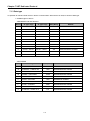
Revision History
Version
Date
Remark
Page
V 1.0
2006.6
1. First Edition
-
V 1.1
2007.7
1. Position and Special function contents separated
(1) Position function contents separated
(position part published)
-
(2) PID control and Ch. 12 Analog IO module contents
separated
2. Contents added
(1) Naming standard added
(2) Caution when selecting IO module added
(3) Installation and wiring contents added
3. Content modified
(1) Safety instruction modified
(2) System Configuration modified
(3) High speed counter function modified
(4) External dimension modified
V 1.2
2008.3
2-3 ~ 2-6
7-1 ~ 7-6
10-1 ~ 10-18
1~6
2-7 ~ 2-10
8-6 ~ 8-8
App. 2-1 ~ 2-4
1. XGB compact type ‘H’ type added
Ch. 9
2. Built-in communication content separated
(1) Ch.9 built-in communication function separated
(Cnet I/F user manual)
V 1.3
2010.3
1. XEC compact type added
V 1.4
2010.5
1. Standard format applied
2. Modbus protocol added
3. Contents changed
(1) Ch. 5 Communication function
→ Ch. 6 Server function and P2P service
(2) Ch. 6 Remote connection → Ch. 5 Remote connection
V 1.5
2013.4
1. Main unit added
(1) XBC/XEC ‘E’ type
(2) XBC/XEC ‘S/SU’ type
(3) XBC/XEC ‘H’ type
V 1.6
V1.7
V1.8
2014.2
2014.11
2015.1
2. Contents added
(1) ‘NOTE’ for XGT Dedicated Protocol
1. LS Bus Protocol added
2. Ch.8 ~ Ch.12 → Ch.9 ~ Ch.13
3. Modified available device type
1. Ch.6 Server function and P2P service
(1) Added UDATA instruction description
2. Ch.11 Example program
(1) Example of sending SMS by using CDMA modem
XG5000 V4.0 UI Updated
Ch. 8
Ch. 5, Ch. 6
2-4 ~ 2-7
7-6
Ch.8
Ch.9 ~ Ch.13
Ch.7
Ch6
Ch11
Entire
※ The number of User’s manual is indicated the right side of the back cover.
Copyrights ⓒ 2006 LSIS Co., Ltd
All Rights Reserved.
About User’s Manual
About User’s Manual
Congratulations on purchasing PLC of LSIS Co.,Ltd.
Before use, make sure to carefully read and understand the User’s Manual about the functions,
performances, installation and programming of the product you purchased in order for correct use and
importantly, let the end user and maintenance administrator to be provided with the User’s Manual.
The Use’s Manual describes the product. If necessary, you may refer to the following description and order
accordingly. In addition, you may connect our website(http://eng.lsis.biz/) and download the information as a
PDF file.
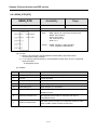
Relevant User’s Manual
Title
XG5000 User’s
Manual
XG5000 User’s
Manual
XGK/XGB Series
Instruction
XGI/XGR/XEC Series
Instruction
XGB Hardware
User’s Manual
XGB Hardware
User’s Manual (IEC)
XGB Analog
User’s Manual
XGB Position
User’s Manual
XGB Cnet I/F
User’s Manual
XGB Fast Ethernet I/F
User’s Manual
Description
It describes how to use XG5000 software especially about
online functions such as programming, printing, monitoring
and debugging by using XGT series products.
It describes how to use XG5000 software especially about
online functions such as programming, printing, monitoring
and debugging by using XGB(IEC)
It describes how to use the instructions for programming
using XGK/XGB series.
It describes how to use the instructions for programming
using XGB(IEC) series.
It describes how to use the specification of power/input
/output/expansion modules, system configuration and built-in
High-speed counter for XGB basic unit.
It describes how to use the specification of power/input
/output/expansion modules, system configuration and built-in
High-speed counter for XGB basic unit.
It describes how to use the specification of analog
input/analog output/temperature input module, system
configuration and built-in PID control for XGB basic unit.
It describes how to use built-in positioning function for XGB
unit.
It describes how to use built-in communication function for
XGB basic unit and external Cnet I/F module.
It describes how to use XGB FEnet I/F module.
No. of User
Manual
10310000512
10130000834
10310000510
10130000833
10310000926
10130001059
10310000920
10310000927
10310000816
10310000873
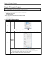
◎ Contents ◎
Chapter 1 General---------------------------------------------------------------------------------------------- 1-1 ~ 1-2
1.1 General --------------------------------------------------------------------- 1-1
1.2 Characteristic--------------------------------------------------------------- 1-2
Chapter 2 Specification -------------------------------------------------------------------------------------- 2-1 ~ 2-8
2.1 General Specification ------------------------------------------------------------------------- 2-1
2.2 Performance Specification -------------------------------------------------------------------- 2-2
2.3 Name and Function of each part ---------------------------------------------------------- 2-4
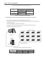
Chapter 3 System Configuration--------------------------------------------------------------------------3-1~ 3-9
3.1 XGB System Configuration ------------------------------------------------------------- 3-1
3.1.1 “H” type system configuration --------------------------------------------------- 3-1
3.1.2 “S” type System Configuration ---------------------------------------------------- 3-2
3.2 Available System Configuration ------------------------------------------------------------ 3-3
3.2.1 1:1 Connection between PC (HMI) (No modem) -------------------------------------- 3-3
3.2.2 1:1 Dedicated modem connection with PC (HMI) ---------------------------------------- 3-6
3.2.3 Modem connection with PC and communication between Cnet I/F modules -------- 3-6
3.2.4 Dedicated communication with PC (HMI) and different type RS-422 communication ---- 3-7
3.2.5 Optical modem communication for moving material communication ------------------- 3-8
3.2.6 Wireless modem communication for communication between revolution bodies --------------- 3-9
Chapter 4 Basic Setting -------------------------------------------------------------------------------------- 4-1 ~ 4-9
4.1 Setting Sequence of Product --------------------------------------------------------- 4-1
4.2 PLC Type Setting and How to Register Communication Module --------------------------------- 4-2
4.2.1 Making new project ---------------------------------------------------- 4-2
4.2.2 In case of off line, method on Cnet I/F module registration -------------------- 4-3
4.2.3 How to register Cnet I/F module in case of online ---------------------- 4-3
4.2.4 Read parameter saved in PLC ------------------------------------------------------------------- 4-5
4.3 How to Set Basic Parameter ------------------------------------------------------- 4-6
4.3.1 Setting item ------------------------------------------------------------- 4-7
4.3 .2 Se tt in g m etho d - - - - - - - - - - - - - - - - - - - - - - - - -- - -- - - - -- - - - - - - - - - - - - - - - - - - -- - -- - - - 4- 9
Chapter 5 Remote Connection -------------------------------------------------------------------------- 5-1 ~ 5-11
5.1 Remote connection ------------------------------------------------------------------------------------------- 5-1
5.1.1 General ---------------------------------------------------------------------------- 5-1
5.1.2 XG5000 remote connection -------------------------------------------------------- 5-1
5.1.3 Remote connection between Cnet I/F modules-------------------------------- 5-8
Chapter 6 Server function and P2P service---------------------------------------------------------- 6-1 ~ 6-39
6.1 Server Modbus Service----------------------------------------------------------------------------- 6-1
6.1.1 XGT dedicated server------------------------------------------------------------------- 6-2
6.1.2 Modbus server ----------------------------------------------------------------------- 6-2
6.2 P2P Service ---------------------------------------------------------------------------- 6-4
6.2.1 General ------------------------------------------------------------------------------------------------- 6-4
6.2.2 P2P parameter configuration -------------------------------------------------------------------- 6-5
6.2.3 Channel information -------------------------------------------------------------------------------- 6-6
6.2.4 Block information -------------------------------------------------------------------------------- 6-7
6.3 XGT Client Service -------------------------------------------------------------------------------------------- 6-8
6.3.1 Channel Setting -------------------------------------------------------------------------------------- 6-8
6.3.2 P2P Block Setting ----------------------------------------------------------------------------------- 6-9
6.3.3 Parameter Write ------------------------------------------------------------------------------------ 6-10
6.3.4 Enable Link ------------------------------------------------------------------------------------------ 6-10
6.3.5 Diagnosis --------------------------------------------------------------------------------------------- 6-11
6.4 Modbus Client Service ------------------------------------------------------------------------------------- 6-12
6.4.1 Channel Setting ------------------------------------------------------------------------------------ 6-12
6.4.2 P2P Block Setting ---------------------------------------------------------------------------------- 6-13
6.4.3 Parameter Write ------------------------------------------------------------------------------------ 6-14
6.4.4 Enable Link ------------------------------------------------------------------------------------------ 6-15
6.4.5 Diagnosis -------------------------------------------------------------------------------------------- 6-15
6.5 User Frame Definition -------------------------------------------------------------------------------------- 6-16
6.5.1 Structure of user definition frame -------------------------------------------------------------- 6-16
6.5.2 Channel Setting ------------------------------------------------------------------------------------ 6-19
6.5.3 Writing transmission frame ---------------------------------------------------------------------- 6-19
6.5.4 Writing receive frame --------------------------------------------------------------------------- 6-22
6.5.6 Parameter Write ------------------------------------------------------------------------------------ 6-25
6.5.7 Enable Link ------------------------------------------------------------------------------------------ 6-25
6.5.8 Diagnosis -------------------------------------------------------------------------------------------- 6-26
6.6 UDATA Instruction ------------------------------------------------------------------------------------------- 6-27
6.6.1 SEND_UDATA [IEC] ------------------------------------------------------------------------------- 6-27
6.6.2 RCV_UDATA [IEC] --------------------------------------------------------------------------------- 6-29
6.6.3 SEND_DTR [IEC] ---------------------------------------------------------------------------------- 6-30
6.6.4 SEND_RTS [IEC] ---------------------------------------------------------------------------------- 6-31
6.6.5 SNDUDATA [MK] ----------------------------------------------------------------------------------- 6-32
6.6.6 RCVUDATA [MK] ----------------------------------------------------------------------------------- 6-34
6.6.7 SENDDTR [MK] ------------------------------------------------------------------------------------ 6-36
6.6.8 SENDRTS [MK] ------------------------------------------------------------------------------------ 6-38
Chapter 7 XGT Dedicated Protocol -------------------------------------------------------------------- 7-1 ~ 7-19
7.1 XGT Dedic ated Protoc ol - --- --- --- --- ---- ---- --- --- --- --- ---- --- --- --- --- --- --- --- 7- 1
7.1.1 Frame structure ----------------------------------------------------------------- 7-2
7.1.2 List of commands ----------------------------------------------------------------- 7-3
7.1.3 Data type ----------------------------------------------------------------------- 7-4
7.2 Detail of instruction -------------------------------------------------------------------------------------------- 7-6
7.2.1 Individual reading of device (R(r)SS) ----------------------------------------------------------- 7-6
7.2.2 Direct variable continuous reading (R(r)SB) -------------------------------------------------- 7-9
7.2.3 Individual writing of device (W(w)SS) --------------------------------------------------------- 7-12
7.2.4 Continuous writing of device (W(w)SB) ------------------------------------------------------ 7-14
7.2.5 Monitor variable register (X##) ----------------------------------------------------------------- 7-16
7.2.6 Monitor execution (Y##) -------------------------------------------------------------------------- 7-18
Chapter 8 LS Bus Protocol ------------------------------------------------------------------------------- 8-1 ~ 8-6
8.1 LS Bus Protocol -------------------------------------------------------------------------------- 8-1
8.1.1 Frame structure ---------------------------------------------------------------------------- 8-1
8.1.2 List of commands ------------------------------------------------------------------------ 8-2
8.2 Detail of instruction -------------------------------------------------------------------------------- 8-3
8.2.1 Continuous writing to inverter device (W) ----------------------------------------------------- 8-3
8.2.2 Inverter continuous reading (R) ----------------------------------------------------------------- 8-5
Chapter 9 Modbus Communication -------------------------------------------------------------------- 9-1 ~ 9-16
9.1 General ------------------------------------------------------------------------------------------------ 9-1
9.2 Modbus Protocol -------------------------------------------------------------------------------------- 9-1
9.2.1 Kind of modbus protocol------------------------------------------------------------------- 9-1
9.2.2 Structure of modbus protocol------------------------------------------------------------------ 9-1
9.3 Structure of Frame --------------------------------------------------------------------------------------- 9-3
9.3.1 Structure of Frame in the ASCII mode -------------------------------------------------------- 9-3
9.3.2 Frame structure in the RTU mode ----------------------------------------------------- 9-4
9.3.3 Data and expression of address -------------------------------------------------------- 9-5
9.4 Modbus Protocol------------------------------------------------------------------------------------ 9-6
9.4.1 Reading data of bit type at the bit output (01) ------------------------------------------------ 9-6
9.4.2 Read Input Status (02) ----------------------------------------------------------------------- 9-8
9.4.3 Read Holding Registers (03) ---------------------------------------------------------------------- 9-9
9.4.4 Read Input Registers (04) ----------------------------------------------------------------------- 9-10
9.4.5 Force Single Coil (05) ----------------------------------------------------------------------------- 9-11
9.4.6 Preset Single Register (06) ---------------------------------------------------------------------- 9-12
9.4.7 Force Multiple Coils (0F) ------------------------------------------------------------------------- 9-13
9.4.8 Preset Multiple Registers (10) ------------------------------------------------------------------ 9-15
Chapter 10 Diagnosis ------------------------------------------------------------------------------------- 10-1 ~ 10-9
10.1 Diagnosis Function of XG5000 ------------------------------------------------------------------------- 10-1
10.1.1 Checking status of main unit ------------------------------------------------------------------ 10-2
10.1.2 Communication module information --------------------------------------------------------- 10-2
10.1.3 Frame monitor ------------------------------------------------------------------------------------- 10-3
10.1.4 Status by service --------------------------------------------------------------------------------- 10-4
10.2 Trouble Shooting by Error ------------------------------------------------------------------------------ 10-7
10.2.1 Trouble shooing when P2P parameter setting error occurs in case of XG5000
connection -------------------------------------------------------------------------------------------10-7
10.2.2 Trouble shooting when communication is not done after P2P client setting - 10-7
10.2.3 Trouble shooting when response frame is missed in case of acting as client and
using RS-485 ----------------------------------------------------------------------------------------------- 10-7
10.2.4 Two response frame are dealt with as unknown when executing frame monitor--10-8
10.2.5 Unable to analyze TRX frame ----------------------------------------------------------------- 10-8
10.2.6 Unable to know which one is reason of error, client or server ------------------------ 10-8
10.2.7 Communication is not normal or communication is not executed repeatedly
-------------------------------------------------------------------------------------------------10-9
Chapter 11 Example Program------------------------------------------------------------------------- 11-1 ~ 11-25
11.1 Setting of Cnet I/F module in the XG5000 ----------------------------------------------------------- 11-1
11.1.1 In case of acting as server ------------------------------------------------- 11-1
11.1.2 In case of acting as P2P service (client) -------------------------------- 11-3
11.2 Dedicated Communication Example ------------------------------------------------------- 11-6
11.2.1 Settings of XGT server ---------------------------------------------------- 11-7
11.2.2 Settings of XGT client ---------------------------------------------------- 11-8
11.2.3 Checking the operation ------------------------------------------------------ 11-11
11.3 Modbus Communication Example ----------------------------------------------------- 11-12
11.3.1 Modbus RTU server setting ------------------------------------------------------------------ 11-13
11.3.2 Setting of Modbus RTU client ----------------------------------------------------------- 11-15
11.4 User defined Communication Example ------------------------------------------------------------- 11-20
11.4.1 User defined communication example system configuration ------------------------ 11-20
11.4.2 User definition communication frame structure ----------------------------------------- 11-21
11.4.3 User definition communication parameter setting -------------------------------------- 11-22
11.5 SMS transmission method using the CDMA modem -------------------------------------------- 11-26
11.5.1 SMS send message using CDMA modem ------------------------------------------------ 11-28
Chapter 12 Installation and Wiring ------------------------------------------------------------------ 12-1 ~ 12-24
12.1 Safety Instruction ------------------------------------------------------------------------------------------- 12-1
12.1.1 Fail safe circuit -------------------------------------------------------------------------- 12-3
12.1.2 PLC heat calculation -------------------------------------------------------------- 12-6
12.2 Attachment/Detachment of Modules -------------------------------------------------------- 12-8
12.2.1 Attachment/Detachment of modules ------------------------------------------------ 12-8
12.2.2 Caution in handling -------------------------------------------------------------------- 12-12
12.3 Wire -------------------------------------------------------------------------------------------------- 12-13
12.3.1 Power wiring --------------------------------------------------------------------------- 12-13
12.3.2 I/O Device wiring ----------------------------------------------------------------- 12-16
12.4 Channel Operation during Normal Run -------------------------------------------------- 12-17
12.5 Communication Interface Connection Method ------------------------------------------------ 12-18
12.5.1 RS-232C Interface (XBL-C21A) ---------------------------------------------------- 12-18
12.5.2 RS-422/485 interface (Built-in communication) ------------------------------- 12-20
12.5.3 RS-422 interface (XBL-C41A) ---------------------------------------------------- 12-21
12.6 Cable Specifications --------------------------------------------------------------------------- 12-23
12.6.1 Electrical characteristic ------------------------------------------------------------- 12-23
12.5.2 External characteristic ------------------------------------------------------------ 12-23
12.7 Terminal Resistance (In case of using RS-422/485) -------------------------------------------- 12-24
Chapter 13 Maintenance --------------------------------------------------------------------------------- 13-1 ~ 13-2
13.1 Maintenance and Inspection -------------------------------------------------------------- 13-1
13.2 Daily Inspection ------------------------------------------------------------------------------ 13-1
13.3 Periodic Inspection --------------------------------------------------------------------------------- 13-2
Appendix ------------------------------------------------------------------------------------------------------ A1-1 ~ A4-4
Appendix 1 Definition of Terms ------------------------------------------------------------------ A1-1
Appendix 1.1 General Terms --------------------------------------------------------------------------- A1-1
Appendix 1.2 Serial Communication Terms ----------------------------------------------- A1-2
Appendix 2 Communication Relay List (L) -------------------------------------------------------------- A2-1
Appendix 2.1 Communication Relay (L) List ---------------------------------------------- A2-1
Appendix 2.2 Network Register (N) List -------------------------------------------------- A2-4
Appendix 3 Communication Error Code ------------------------------------------------------------- A3-1
Appendix 3.1 XGT Server Error Code -------------------------------------------------- A3-1
Appendix 3.2 Modbus Server Error Code --------------------------------------------- A3-2
Appendix 3.3 P2P Client Error Code ------------------------------------------------------------- A3-2
Appendix 4 Dimension (Unit: mm) -------------------------------------------------------------------------- A4-1
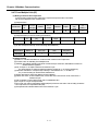
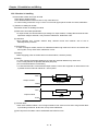
Chapter 1 General
Chapter 1 General
1.1 General
This user manual provides the information of Cnet I/F among XGB PLC system network about
specification/performance and how to operate. Configuration of user manual is as follows.
Chapter
Item
Content
1
General
2
Specification
3
System configuration
4
Basic setting
5
Remote connection
Describes CPU connection method by communication channel through
XG5000.
6
Server function and
P2P service
Describes server for data communication between PLC and P2P parameter
setting.
7
XGT dedicated
protocol
Describes XGT dedicated communication frame structure.
8
LS Bus Protocol
Describes LS bus protocol structure.
9
Modbus
communication
Describes Modbus protocol structure.
10
Diagnosis function
Describes about self diagnosis by XG5000
11
Example program
Describes example program for communication test.
12
Installation and
wiring
13
Maintenance
App.1
Term
App.2
Flag list
App.3
Communication error
code
App.4
Dimension
Describes configuration of manual, product characteristic and term
Indicates general specification and performance specification of each module
used XGB PLC.
Describes basic communication parameter setting.
Describes basic communication setting.
Describes installation and wiring.
Describes maintenance.
Describes term used in this manual
Describes parameter setting N area, flag L related with Cnet I/F.
Describes XGT server, modbus server, P2P error code.
Describes dimension of communication module.
1-1
Chapter 1 General
1.2 Characteristic
(1)
By using XG5000 operated in window environment, since the user can write communication speed,
communication mode (protocol), connection with external device is easy.
(2)
RS-232C 1 port, RS-485 1 port as main unit built-in Cnet is supported. Two type of Cnet I/F
module as extension, RS-232C 1 port (XBL-C21A), RS-422(485) 1port (XBL-C41A) is provided.
(3)
It operates independently according to channel, since protocol data written by user is managed by
main unit, in case communication module is changed other than communication module,
additional setting/download is not necessary.
(4)
Device read/write by using XGT dedicated/modbus/user defined protocol is available.
(5)
It provides communication function in which multidrop, up to 32 connection is available in case of
using RS-422/485.
(6)
Setting of diverse communication speed is available.
(1200,2400,4800,9600,19200,38400,57600,115200bps)
(7)
1:1 and 1:N communication are available.
(8)
With abundant self-diagnosis, trouble diagnosis is simple.
(9)
It supports dedicated server/client, modbus server/client, user defined communication function.
(10)
In case of XBL-C21A module, modem communication is provided, by which controlling remote
PLC is available.
1-2
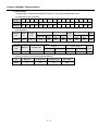
Chapter 2 specification
Chapter 2 Specification
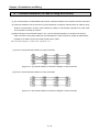
2.1 General Specification
General specification of XGB PLC is as follows.
No.
1
2
3
4
Item
Specification
Operating
temp.
Storage temp.
Operating
humidity
Storage
humidity
Related specifications
0℃∼+55℃
-25℃∼+70℃
5∼95%RH, no dew allowed
5∼95%RH, no dew allowed
For discontinuous vibration
Frequency
Acceleration
Amplitude
-
3.5mm
9.8㎨
-
5≤f< 8.4㎐
5
Vibration
proof
8.4≤f≤150㎐
For continuous vibration
Frequency
Acceleration
Amplitude
-
1.75mm
5≤f< 8.4㎐
6
Impact proof
Noise proof
Each 10 times
in X,Y,Z
directions
8.4≤f≤150㎐
4.9㎨(0.5G)
* Max. impact acceleration: 147㎨(15G)
* Authorized time: 11㎳
* Pulse wave : Sign half-wave pulse
(Each 3 times in X,Y,Zdirections)
IEC 61131-2
IEC 61131-2
IEC 60068-2-27
AC:±1,500V
DC: ±900 V
Square wave impulse noise
7
Number
Test spec of LS
Industrial Systems
Static electric discharging
±4 kV (contact discharging),
IEC 61131-2,
IEC 61000-4-2
Radiation electromagnetic
80 ~ 1,000MHz, 10 V/m
IEC 61131-2,
IEC 61000-4-3
Fast
Transient
/burst
Class
Power
Digital/Analog I/O
module
communication interface
2kV
1kV
Voltage
8
Ambient
conditions
No corrosive gas or dust
9
Operating
height
2000m or less
10
Pollution level
11
Cooling type
IEC 61131-2,
IEC 61000-4-4
2 or less
Natural air cooling
Notes
[1] IEC (International Electro technical Commission):
An international nongovernmental organization which promotes internationally cooperated
standardization in electric/electronic fields, publishes international standards and manages applicable
estimation system related with.
[2] Pollution level: An index indicating pollution level of the operating environment which decides
insulation performance of the devices. For instance, Pollution level 2 indicates the state generally that
only non-conductive pollution occurs. However, this state contains temporary conduction due to dew
produced.
2-1
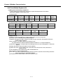
Chapter 2 specification
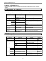
2.2 Performance Specification
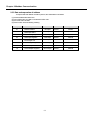
(1) Built-in Cnet performance specification
Performance specification of XGB built-in Cnet is as follows.
Specification
Item
Channel 1
Serial communication method
RS-232C
Modem connection function
Channel 2
RS-485
-
-
Act as communication client
- XGT dedicated protocol client
Operation
P2P
mode
- Modbus ASCII/RTU client
- User defined communication
(Operation
- LS Bus Client
define by
channel)
Server
Notes 1)
- XGT dedicated protocol server
- Modbus ASCII/RTU server
Data
type
Data bit
7 or 8
Stop bit
1 or 2
Parity
Even/Odd/None
Synchronization type
Transmission speed
(bps)
Station No. setting
Asynchronous type
1200/2400/4800/9600/19200/38400/57600/115200 bps available
Setting range: 0~255
Max. station No. available: 32 stations
Transmission
Max. 15m
distance
Diagnosis function
Max. 500m
Check available by XG5000 diagnosis service
Notes
Note 1) <UDATA for CDMA modem communication applicable version>
Series
Version
Series
Version
XBM
XBCEX
-
XBCH
XBCSU
XBCS
V2.40 or above V1.50 or above
XBCEB
XECH
XECSU
V1.80 or above V1.40 or above
XBCE
XECE
-
XG5000
V3.71 or above
-
Notes 2) < LS Bus Client applicable version>
Series
Version
Series
Version
XBM
XBCH
XBCSU
XBCS
XBCE
XG5000
V3.40 or above V2.30 or above V1.40 or above V1.30 or above V1.20 or above V3.69 or above
XBCEX
XBCEB
XECH
XECSU
XECE
V1.01 or above V1.01 or above V1.70 or above V1.30 or above V1.10 or above
-
Note 3) Max. 32 stations are available for consist the client and server. Station number setting range is 0~255
2-2
Chapter 2 specification
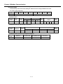
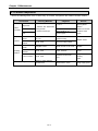
(2) Extension Cnet performance specification
XGB extension Cnet communication module performance specification is as follows
Specification
Item
Serial communication channel
Modem connection function
XBL-C21A
XBL-C41A
RS-232C 1 channel
RS-422(485) 1 channel
External modem connection
-
available
Operates as communication client
- XGT dedicated protocol client
Operation
P2P
mode
- User defined communication
(Operation
- LS Bus Client
definition
by port)
- Modbus ASCII/RTU client
Server
- XGT dedicated protocol server
- Modbus ASCII/RTU server
Data
type
Data bit
7 or 8
Stop bit
1 or 2
Parity
Even/Odd/None
Synchronization type
Asynchronous type
Transmission speed (bps)
1200/2400/4800/9600/19200/38400/57600/115200 bps available
Station No. setting
Transmission
distance
Setting range: 0~255
Note 1)
Max. station No. available: 32 stations
RS-232C: 15m
(Extension available in case RS-422/485: max 500m
of using modem)
Diagnosis function
Check available by LED and XG5000 diagnosis service
Consumption current
120mA
120mA
Weight
56g
56g
Notes
Note 1) Max. 32 stations are available for consist the client and server. Station number setting range is 0~255
2-3
Chapter 2 specification
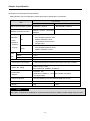
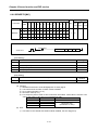
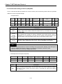
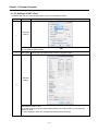
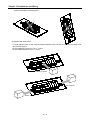
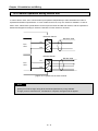
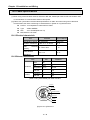
2.3 Name and Function of each part
XBM
“S” Type
XBM-DR16S
XBM-DN16/32S
⑦
⑦
⑥
①
⑥
①
②
②
⑤
⑤
③
④
③
④
8-1
⑧
8-3
8-2
No.
Name
①
Input indication LED
②
PADT connection
connector
Input connector and
terminal block
Output connector and
terminal block
③
④
⑤
Key switch
⑥
Output indication LED
⑦
Status indication LED
8-1
⑧
8-2
8-3
Built-in RS-485
Connection
connector
Built-in RS-232C
connection
connector
Power connector
Purpose
Input indication LED
PADT connection connector
Input connector and terminal block
Output connector and terminal block
RUN / STOP key switch
- In case key switch is STOP, remote mode change available
Output indication LED
Indicates operation status of CPU module
- PWR(Red): Power status indication
- RUN(Green): RUN status indication
STOP mode: Off / RUN mode : On
- Error(Red): Flicker in case error occurs
Built-in RS-485 connection connector
- “+”, “-“ terminal connection connector ofRS-485 communication
Built-in RS-232C connection connector
-“TD”, “RD”, “SG” terminal connection connector of RS-232C
communication
DC24V power connector
2-4
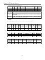
Chapter 2 specification
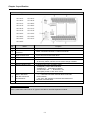
XBC/XEC
“E” type
XBC-DR10E
XEC-DN10E
XBC-DN10E
XEC-DN14E
XBC-DP10E
XEC-DN20E
XBC-DR14E
XEC-DN30E
XBC-DN14E
XEC-DP10E
XBC-DP14E
XEC-DP14E
XBC-DR20E
XEC-DP20E
XBC-DN20E
XEC-DP30E
XBC-DP20E
XEC-DR10E
XBC-DR30E
No.
Name
Purpose
①
Input indication LED
Input indication LED
②
PADT connection
connector
PADT connection RS-232C 1 channel connector
③
Input terminal block
Input connector and terminal block
④
⑤
Output terminal block
Key switch
⑥
⑦
Output indication LED
Status indication LED
⑧
Built-in RS-232C/
RS-485 Connection
terminal block
Power terminal
Output connector and terminal block
RUN / STOP key switch
-In case key switch is STOP, remote mode change available
Output indication LED
Indicates basic unit’s operation status
- PWR(Red) : power status indication
- RUN(Green) : RUN status indication
- STOP mode : Off
/ RUN mode : On
- Error(Red): flicker in case error occurs
Built-in RS-485 connection terminal block
- “+”,”-“ terminal connection terminal block of RS-485
communication
- “TD”,”RD”,”SG” terminal connection terminal block of
RS-232C communication
AC100~240V power terminal block
Notes
Notes 1) XBC/XEC main units of "E” type are not able to use XGB expansion module.
2-5
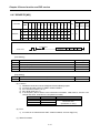
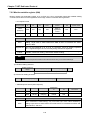
Chapter 2 specification
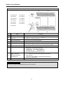
XBC/XEC
“S/SU” type
XBC-DN20S(U)
XEC-DN20SU
XBC-DR20SU
XEC-DN30SU
XBC-DN30S(U)
XEC-DN40SU
XBC-DR30SU
XEC-DN60SU
XBC-DN40SU
XEC-DR20SU
XBC-DR40SU
XEC-DR30SU
XBC-DN60SU
No.
Name
Purpose
①
Input indication LED
Input indication LED
②
PADT connection
connector
PADT connection USB(USB 1.1 supported) 1 channel,
Notes 1)
RS-232C 1 channel connector
③
Input terminal block
Input connector and terminal block
④
⑤
Output terminal block
Key switch
⑥
⑦
Output indication LED
Status indication LED
⑧
Built-in RS-232C/
RS-485 Connection
terminal block
Power terminal
Output connector and terminal block
RUN / STOP key switch
-In case key switch is STOP, remote mode change available
Output indication LED
Indicates basic unit’s operation status
- PWR(Red) : power status indication
- RUN(Green) : RUN status indication
- STOP mode : Off
/ RUN mode : On
- Error(Red): flicker in case error occurs
Built-in RS-485 connection terminal block
- “+”,”-“ terminal connection terminal block of RS-485
communication
- “TD”,”RD”,”SG” terminal connection terminal block of
RS-232C communication
AC100~240V power terminal block
Notes
Notes 1) The S-type of XBC/XBC doesn’t provide a usb port.
2-6
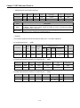
Chapter 2 specification
XBC/XEC
“H” type
XBC-DR32H
XEC-DN32H
XBC-DN32H
XEC-DN64H
XBC-DR64H
XEC-DP32H
XBC-DN64H
XEC-DP64H
XEC-DR32H
XEC-DR64H
No.
Name
Purpose
①
Input indication LED
Input indication LED
②
PADT connection
connector
PADT connection USB(USB 1.1 supported) 1 channel,
RS-232C 1 channel connector
③
Input terminal block
Input connector and terminal block
④
⑤
Output terminal block
Key switch
⑥
⑦
Output indication LED
Status indication LED
⑧
Built-in RS-232C/
RS-485 Connection
terminal block
Power terminal
Output connector and terminal block
RUN / STOP key switch
-In case key switch is STOP, remote mode change available
Output indication LED
Indicates basic unit’s operation status
- PWR(Red) : power status indication
- RUN(Green) : RUN status indication
- STOP mode : Off
/ RUN mode : On
- Error(Red): flicker in case error occurs
Built-in RS-485 connection terminal block
- “+”,”-“ terminal connection terminal block of RS-485
communication
- “TD”,”RD”,”SG” terminal connection terminal block of
RS-232C communication
AC100~240V power terminal block
2-7
Chapter 2 specification
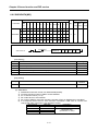
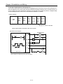
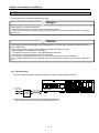
Extension Cnet module
XBL-C41A
No.
①
②
I/F
TX
RX
ERR
①
②
③
Purpose
LED indication
Operation status indication
RS-422/RS-485
Connector for connection with external device
RS-232C connector
LED name
RUN
①
Name
connector
③
XBL-C21A
Connector for connection with external device
LED indication content
LED status
LED status content
On
Normal operation
Off
Abnormal operation
Interface with main unit status
Flicker
Normal operation
indication
Off
Abnormal operation
Flicker
Transmitting frame
Off
Frame transmission completion
Flicker
Receiving frame
Off
Frame receive completion
On
Frame error
Off
Normal frame
Operation status indication
Indication during frame transmission
Indication during frame receiving
Frame error indication
[Table 2.3.1] LED indication content
2-8
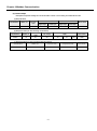
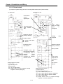
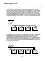
Chapter 3 System Configuration
Chapter 3 System Configuration
XGB PLC is having diverse product suitable for main system, computer link and network system configuration
This chapter describes configuration method and characteristic.
3.1 XGB System Configuration
System configuration of XGB PLC is as follows. Extension I/O module, in case of special module, in “S” type, up
to 7 step connection and in “H” type, up to 10 step connection is available. In communication module, up to 2 step
extensions is available.
3.1.1 “H” type system configuration
Main unit
I/O module
Special module
Item
content
• XB(E)C-DxxxH: 32 ~ 384 points
I/O configuration point
Digital I/O module
• Max. 10
Extension module
Analog module
• Max. 10
connection available no.
Communication
• Max. 2
module
Main unit
“H” type
• XBC-DR32/64H
• XBC-DN32/64H
• XEC-DR32/64H
• XEC-DN32/64H
• XBE-DC08/16/32
• XBE-TN08/16/32
Digital I/O module
• XBE-TP08/16/32
• XBE-RY08/16A
• XBE-DR16A
Extension
Product list
• XBF-AD04A
• XBF-RD04A
• XBF-DV04A
• XBF-RD01A
• XBF-DC04A
• XBF-TC04S
Communication
• XBL-C41A
• XBL-C21A
module
• XBL-EMTA
Memory module
• XBO-1024A
module
Analog module
Option
module
Communication
module
3-1
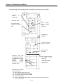
Chapter 3 System Configuration
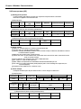
3.1.2 “S” type System Configuration
Main unit
I/O module Special module Communication module
Item
Content
• XBM-DxxxS : 16 ~ 352 point
I/O configuration point
Extension module
connection available
no.
Main unit
Digital I/O module
• Max. 7
Analog module
• Max. 7
Communication module
• Max. 2
“S” type
• XBM-DR16S
• XBM-DN16/32S
• XBE-DC08/16/32
• XBE-TN08/16/32
• XBE-TP08/16/32
Digital I/O module
• XBE-RY08/16A
• XBE-DR16A
Product
list
Extension
module
Analog module
Communication module
Option
module
• XBF-AD04A
• XBF-RD04A
• XBF-DV04A
• XBF-RD01A
• XBF-DC04A
• XBF-TC04S
• XBL-C41A
• XBL-C21A
• XBL-EMTA
• XBO-1024A
Memory module
3-2
Chapter 3 System Configuration
3.2 Available System Configuration
Communication system by using XGB built-in communication function and Cnet module is diverse. In this
chapter, it describes system configuration example.
.
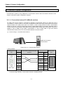
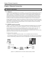
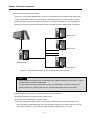
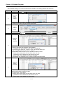
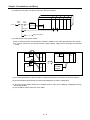
3.2.1 1:1 Connection between PC (HMI) (No modem)
PC (HMI) and Cnet I/F module is connected by RS-232C or RS-422/485 channel, PC (HMI) and PLC is
connected by 1:1 without modem. In most case, PC (HMI) acts as client and Cnet I/F module acts as server which
respond request of PC (HMI). Since there is no modem, in case of using RS-232C channel, communication
distance is max 15m, in case of using RS-422 channel, communication distance is max 500m. Operation mode of
Cnet I/F module is set according to PC (HMI)’s communication method. Wiring method and system connection is
applied in case of XGB “S” type built-in communication. In case of using XGB “H” type and external
communication module, refer to 10.5 communication interface connection method.
(1) In case of using 1:1 connection with normal PC
XGB main unit built-in
communication
[Figure 3.2.1] 1:1 communication with PC
• Wiring method
External form of
PC
PC
Pin no.
Connection number and signal
direction
XGB main unit
Signal
Pin no.
name
1
2
(RXD)
3(TXD)
1
3
SG
4
4
TX
5(GND)
5
RX
2
6
485485+
1
2
3
4
5
7
Female Type
XGB external
form
8
9
In case of using channel 2, connect 485+ and 485- of RS485 terminal.
3-3
Chapter 3 System Configuration
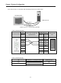
(2) In case of using 1:1 connection with monitoring device such as XGT Panel
XP series (LSIS)
XGB main unit
RS-485 I/F
RS-232C I/F
[Figure 3.2.2] 1:1 communication with HMI
• Wiring method (RS-232C)
XP
XGB main unit
Connection number and
XP external form
Pin no.
signal direction
XGB external
Pin no.
Signal
1
1
485-
2(RXD)
2
485+
3(TXD)
3
SG
4
4
TX
5(GND)
5
RX
6
form
name
1
2
3
4
5
7
Female Type
8
9
Note) In case of PMU, short no.4 and no.6, short no.7 and no.8.
• Wiring method (RS-485)
PMU
Connection no. and signal direction
XGB main unit
485+
485+
485-
485-
3-4
Chapter 3 System Configuration
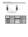
(3) In case of using 1:1 connection with XGB main unit
XGB main unit
XGB main unit
RS-232C I/F
RS-485 I/F
[Figure 3.2.3] 1:1 communication between PLCs
• Wiring method
XGB main unit
XGB main unit
XGB external
form
1
2
3
4
5
Connection no. and
signal direction
Pin no.
Pin
no.
Signal name
1
1
485-
2
2
485+
3
3
SG
4
4
TX
5
5
RX
3-5
Chapter 3 System Configuration
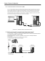
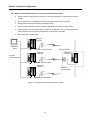
3.2.2 1:1 Dedicated modem connection with PC (HMI)
It is 1:1 communication system connected through dedicated modem through RS-232C channel
with PC (HMI). Normally, PC (HMI) acts as client station, Cnet I/F module acts as server station
which respond request of PC (HMI). Since it uses modem, RS-232C channel should be set as
dedicated modem and long distance communication is available. Operation mode of this module
should be set according to communication method of PC (HMI).
XBM-DN32S XBL-C21A
XBM-DN32S XBL-C21A
Modem
Modem
[Figure 3.2.4] dedicated modem communication with PC
3.2.3 Modem connection with PC and communication between Cnet I/F modules
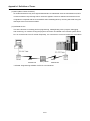
♦ PC and Cnet #1 station is connected by modem through RS-232C channel
♦ Cnet #1 station ~ N station is communication between Cnet I/F module through RS-422 channel
♦ PC acts as client station of Cnet #1 station
♦ Up to max 32 station connection is available in case of Cnet I/F module (RS-422/485
communication)
♦ It sets station 1 among Cnet I/F module as server station
♦ Dedicate modem or dial-up modem available
XGB PLC
Cnet # 1 station
XGB PLC
Cnet # 2 station
XGB PLC
Cnet # N station
RS-422 communication
RS-232C
Communication
3-6
Chapter 3 System Configuration
[Figure 3.2.5] Dedicated modem communication with PC
Module setting
Type
XBL-C41A
PLC Cnet #1
Cnet #2 ~ #N
Station no.
P2P
1
XGT client
XGT server
2~N
[Table 3.2.1] module setting table per station
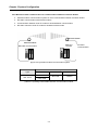
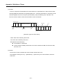
3.2.4 Dedicated communication with PC (HMI) and different type RS-422 communication
♦ Null-modem communication by using PC (HMI) and RS-232C channel
♦ PC (HMI) acts as client station, Cnet I/F module acts as server, at this time, module setting acts as
RS-232C XGT server
♦ Cnet I/F module RS-422 channel acts as P2P mode.
♦ It transmits indication data to display module of mosaic panel through RS-422 channel
♦ Reading display transmission data from PC
HMI - PC
(GLOFA VIEW)
XGB PLC
Cnet # 1
RS-422 communication
RS-232C communication
[Figure 3.2.6] 7-Segment operating system for RS-422
Type
PLC Cnet #1
XBL-C21A
Module setting
XBL-C41A
Station no.
XGT server
P2P
1
[Table 3.2.2] Module setting table per station
3-7
Chapter 3 System Configuration
3.2.5 Optical modem communication for moving material communication
♦
Optical modem communication system for Cnet communication on material above moving
linearly.
♦
P2P communication or dedicated mode communication with monitoring device
♦
RS-232C/RS-422 communication with optical modem
♦
Communication between Cnet I/F module is dedicated server/client communication
♦
Optical modem connected with Cnet I/F module on mobile body can communicate with the
other optical modem only when positioned in communication available
♦
Main application: Parking tower
XGB PLC
Cnet # 1
Optical
Monitoring
device
modem
RS-232C communication
Moving material
XGB PLC
Cnet # 2
RS-422
communication
XGB PLC
Cnet # 4
Optical
modem
RS-232C communication
XGB PLC
Cnet # 3
광
모
뎀
RS-232C
communication
Optical
modem
RS-232C communication
[Figure 3.2.7] Optical modem communication system
3-8
Chapter 3 System Configuration
3.2.6 Wireless modem communication for communication between revolution bodies
♦
Wireless modem communication system for Cnet communication between revolution bodies
♦
RS-232C communication with wireless modem
♦
Communication between Cnet I/F module is dedicated/client communication
♦
RS-232C channel of Cnet I/F module is dedicated modem mode
Wireless modem
Wireless modem
XGB PLC
Cnet # 2
RS-232C communication
[Figure 3.2.8] wireless modem communication system
Module setting
Type
RS-232C
Dedicated mode
XBL-C21A
RS-422
Station
Not used
2 station
User mode
[Table 3.2.3] setting content table between communication module
3-9
RS-232C
communication
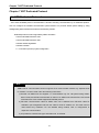
Chapter 4 Basic Setting
Chapter 4 Basic Setting
4.1 Setting Sequence of Product
It describes installation of product and sequence. Install system by be operated by the following
sequence.
Operation sequence
Equip Cnet I/F module to XGB system
(It is applied in case of using external Cnet I/F module)
Connect Cnet I/F module with device to communicate
by cable.
Cable wiring and connect terminal resistance.
After power on, check LED status of communication
module
Check whether interface of communication with CPU
is normal or not.
Set P2P parameter and basic setting at XG5000.
Set parameter according to network configuration at
XG5000, download parameter
Enable link at XG5000.
Not enable link act as server.
Operation start
Note
1) In Cnet I/F module, hardware station setting is not necessary.
By using XG5000, designate station and basic setting necessary in Cnet communication.
4-1
Chapter 4 Basic Setting
4.2 PLC Type Setting and How to Register Communication Module
To use Cnet I/F function, communication parameter should be written by XG5000. To set system
about Cnet I/F module located in temporary position, register each module at XG5000. Method on
register Cnet I/F module is as follows according to On/Off line status.
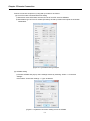
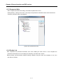
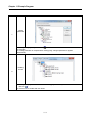
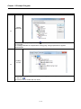
4.2.1 Making new project
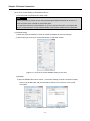
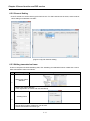
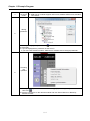
First, after click Project-New Project and input project name, select XGB series as PLC series.(In
case of IEC type, select XGB(IEC)) About CPU type, in case of “S” type, select “XGB-XBMS”, in case
of “H” type, select “XBC-XBCH”.
[Figure 4.2.1] New project making screen
4-2
Chapter 4 Basic Setting
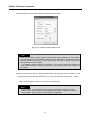
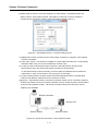
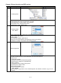
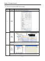
4.2.2 In case of off line, method on Cnet I/F module registration
In the status PLC is not connected, in case the user set about communication module and write
parameter related with communication, right click “Unspecified Network” in the project tree and select
[Add Item]-[Communication Module]. Click “Add Module” in the “Select communication module”
window. Then register the Cnet I/F module about wanted slot position in the “Communication Module
Settings” window.
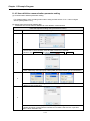
[Figure 4.2.2] Cnet module registration screen
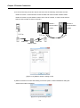
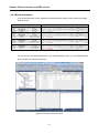
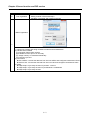
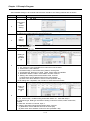
4.2.3 How to register Cnet I/F module in case of online
If you register communication module at online status by using XG5000, you should connect basic
unit. After [Online]-> [Connection] after doing communication setting by using [Online] -> [Connection
Settings] and doing local connection (or remote 1/2 connection). In case of normal connection, lower
menu of “online” is activated, selecting [Online]-> [Diagnosis]-> [I/O Information] and click “I/O Sync”,
then equipped communication module is searched automatically.
[Figure 4.2.3] Cnet I/O information screen
4-3
Chapter 4 Basic Setting
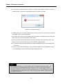
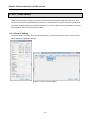
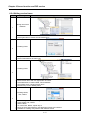
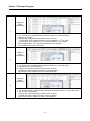
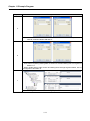
At this time, the following message occurs. Check the message and click “Yes” or “No”.
[Figure 4.2.4] I/O information change message
If you execute Read IO Information, equipped communication module like the following is indicated
IO module information window.
[Figure 4.2.5] Communication module registration compete screen
4-4
Chapter 4 Basic Setting
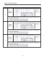
4.2.4 Read parameter saved in PLC
For read the basic setting of communication module and P2P setting that saved in PLC, select
[Project]-[Open from PLC] then set the connection settings and click “OK”.
[Figure 4.2.6] Open form PLC
4-5
Chapter 4 Basic Setting
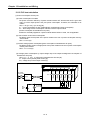
4.3 How to Set Basic Parameter
Communication function used in Cnet I/F module is classified as followings.
1) Server mode service
Without other program at PLC, you can read or write information in PLC and data.
It can act as XGT server providing XGT dedicated protocol and Modbus server providing
RTU/ASCII protocol.
2) Client (P2P) service
Cnet I/F module acts as client in network.
In case designated event occurs, you can read or write memory of other station.
It can act as XGT client and Modbus client.
In case of sending/receiving user wanted frame and communicating with other device.
You can define P2P block with max. 32 per one channel acting independently.
3) Loader service
By using remote 1/2, you can monitor/download program about remote PLC.
To use Cnet I/F module, you should set transmission specification such as data type like transmission
speed and data/stop bit.
You should select transmission specification of system to be same with specification of system.
Written standard setting value is saved CPU module of PLC and this value keeps though power goes
off and this value is not changed before writing. Also though Cnet I/F module is changed and new
module is installed, the standard setting value saved at CPU module previously written is applied to
new module automatically. Standard communication setting parameter and P2P, all parameter is
applied if download is complete.
4-6
Chapter 4 Basic Setting
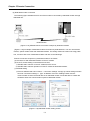
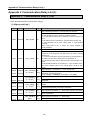
4.3.1 Setting item
When setting Cnet communication parameter, the fact the user should define is as follows [Table 4.3.1]
[Figure 4.3.1] Built-in communication standard setting screen
Item
Setting content
Station no. • You can set from station 0 to station 255.
Communicati
• 1200, 2400, 4800, 9600, 19200, 38400, 57600,115200 bps available
on speed
Data bit
•7
Parity bit
• None, Even, Odd available
Stop bit
• 1 or 2 bit available
or 8 bit available
• It is fixed as follows according to Cnet type
1) Built-in communication → channel 1 : RS-232C , channel 2 : RS-485
2) XBL-C41A → channel 1 : not used, channel 2: RS-422/RS-485
3) XBL-C21A → channel 1 : not used, channel 2: RS-232C
• It sets the time waiting respond after sending frame
Response
1) Setting: It can be set when active mode is “Use P2P”.
waiting time
2) Waiting time: 100ms+(value X 100ms)
• It sets interval of communication frame
Delay time
1) Setting: It can be set when communication channel is RS-422/485.
Delay time • If receives the character while in set time, it process as one frame.
between
1) Setting: It can be set regardless of setting
Note 1)
character
2) If set delay time “0”, 3.5 character time
will apply that fits communication speed.
Communicati
on channel
[Table 4.3.1] communication parameter setting item
4-7
Chapter 4 Basic Setting
The meaning of each item is as follows.
1) Parity bit
Cnet I/F module can define three parity bits. Meaning of each parity bit is as follows.
Parity bit type
Meaning
None
Not using parity bit
Even
If the number of 1 in one byte is even, parity bit becomes “0”.
Odd
If the number of 1 in one byte is odd, parity bit becomes “1”.
Reference
[Table 4.3.2] Parity content table
2) Operation mode setting
▪ Sets operation mode
Driver type
P2P
XGT server
Meaning
Reference
Each port acts as client and executes the communication
P2P setting
by setting P2P parameter.
reference
It acts as XGT server supporting XGT dedicated
communication.
Modbus ASCII server
It acts as Modbus ASCII server
Modbus RTU server
It acts as MOdbus RTU server
Dedicated service
Modbus
communication
Modbus
communication
[Table 4.3.3] operation mode setting item
Note
Note 1) Character Time: The time of sending one character. This value can be changed according to
communication speed
In case of communication speed is 9600bps
Character Time=(Bit number of one character(11)/Communication speed)*Character time
=(11/9600)*3.5
=4.01ms
4-8
Chapter 4 Basic Setting
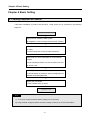
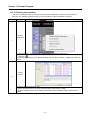
4.3.2 Setting method
You should do like following to operate Cnet I/F module according to communication specification
defined by user. In case of setting like the followings about XBL-C41A (RS-422/485 1 port) installed
slot 2, setting method is as follows.
(1) Communication specification
Channel 2: RS-422, 38400Bps, 8/1/Odd, Null modem, P2P, 2 station, delay time 10 ㎳
Executing XG5000, you register communication module Cnet for setting at each slot position. After
Cnet module is registered, if you double-click Cnet module, the following standard setting window
shows.
[Figure 4.3.2] Communication module setting screen
If standard communication parameter setting ends, download Cnet module.
If you select [Online -> Write], download is executed. After downloading, parameter is applied
shortly.
[Figure 4.3.3] Write Parameter screen
4-9
Chapter 5 Remote Connection
Chapter 5 Remote Connection
5.1 Remote Connection
5.1.1 General
In case PC executing XG5000 is far from XGB PLC, if you use remote connection function of Cnet I/F
module, you can control remote PLC such as program download, upload, program debugging and
monitor. Especially, in case XG5000 is far from PLC, if you use XG5000 remote connection function
and modem connection function of Cnet I/F module, you can access easily by remote connection
through air line. Remote connection is supported at XGB communication module, FEnet I/F module
and Cnet I/F module. Connection between networks is available and you can control remote PLC
through multiple connections. There are two methods for remote connection by using Cnet I/F module,
first, XG5000 is connected with Cnet I/F module of remote PLC through modem, second, XG5000 and
local PLC are connected into CPU through RS-232C, Cnet I/F module of local PLC communicates
with Cent I/F module of remote PLC.
5.1.2 XG5000 remote connection
[Figure 5.1.1] is figure indicating remote connection example where XG5000 and PLC are connected
through modem. Like figure, it is necessary configuration in case PC executing XG5000 is far from
PLC and telephone line and connected by dedicated modem or wireless modem. At this case, you
should connect Cnet I/F module by modem from XG5000 and you should select modem as
connection method at connection option. There are two methods, dedicated modem connection using
dedicated line and dial-up modem connection using public line.
(1) Dial-up modem connection
[Figure 5.1.1] is example using dial-up modem. You can establish remote connection by
connecting dial-up modem to PC and Cnet I/F module (RS-232C). In PC side, you can use external
modem or internal dial-up modem and in Cnet I/F side (RS-232C), you should use external modem.
Public line
Public line
Tandem center
[Figure 5.1.1] XG5000 remote connection example by dial-up modem
5-1
Chapter 5 Remote Connection
Remote connection sequence by using dial-up modem is as follows.
(a) Cnet I/F module connected with PLC setting
1) Sets active mode of RS-232C channel of Cnet I/F as XGT server at XG5000.
2) Sets Modem type of Cnet I/F module (RS-232C) as Dial-up modem and inputs atz in Modem
Initialization.
[Figure 5.1.2] XG5000 setting example
(b) XG5000 setting
1) Execute XG5000 and pop up online settings window by selecting “Online -> Connection
settings”.
Here selects “Connection settings -> Type” as Modem.
[Figure 5.1.3] Modem connection setting screen of XG5000
5-2
Chapter 5 Remote Connection
2) Select settings of “Connection settings” and set detail of modem
[Figure 5.1.4] Modem detail setting screen
Note
Baud rate in modem settings means communication speed between PC and modem,
not communication speed of modem. Baud rate of modem means communication speed
between modem and modem, it is set automatically according to quality of public line
and destination modem’s speed.
For XG5000 remote connection at XGB PLC, you should use RS-232C channel. At
communication standard setting, set “RS-232C dial-up modem” and write it to XGB Cnet
I/F module.
3) Phone number means phone number of modem side connected with Cnet I/F module, in case
of going out from local through extension line, you can use extension number and ‘,’ symbol.
(Ex) In case extension number is ‘9’: set as 9, 0343-398-xxxx
Note
In case modem connected with Cnet I/F module of destination station is through
tandem center, communication is impossible. Namely, there is extension number for
receive station, dial-up modem communication is impossible.
5-3
Chapter 5 Remote Connection
4) In case of selecting connection step as remote 2, like the following, select base and slot
number of remote 1 communication module in detail and communication module station
number of remote 2. Inputs station number set in Cnet I/F module, In case of Cnet channel,
selects communication channel of remote 2.
Remote 1
Remote 2
Communication
Communication
module
module
Public line
Public line
Tandem center
[Figure 5.1.5] Modem remote 2 setting screen
5) Select connection on online after setting connection option, modem initialization dialog box
shows and modem is initialized.
[Figure 5.1.6] Connecting to PLC
5-4
Chapter 5 Remote Connection
6) In case setting of COM channel of modem or connection with modem is wrong or, the error
message shows. At this time, check COM channel or modem connection.
[Figure 5.1.7] Failed connecting
7) If making phone call is complete, XG5000 tries remote connection. In case remote connection
is complete, “Online” menu is activated.
8) This case is same with connection status where connection is established through RS-232C
cable. Here you can use all function of online menu.
9) In case you want to disconnect remote connection, select disconnect at online menu. Then
disconnection menu box shows and remote connection is disconnected.
10) If connection is disconnected, XG5000 quit call automatically and disconnection telephone
connection.
11) If it is success to quit call normally, local and remote modems return to initialization status.
You can establish remote connection through making phone call.
Note
After remote connection, you can use online menu of XG5000 like local connection. You
can use program download/upload/monitor function etc. PLC control through modem is
affected by capability of modem and status of telephone line. In case telephone line is bad,
connection may be canceled. At this time, don’t try reconnection instantly, wait for 30s and
retry again from step 1)
5-5
Chapter 5 Remote Connection
(2) Dedicated modem connection
The following figure indicates that PC and Cent module is connected by dedicated modem through
dedicated line.
Dedicated line
[Figure 5.1.8] XG5000 remote connection example by dedicated modem
[Figure 5.1.8] is example of dedicated modem connection by dedicated line. You can use wireless
modem, optical modem other than dedicated modem. For setting method of modem not using public
line, it is same with case of dedicated modem and refer to the followings.
Remote connection sequence by dedicated modem is as follows.
(a) Connects PC with dedicated modem at Cnet I/F module
(b) Cnet I/F module setting connected at remote PLC
1) Sets RS-232C channel of Cnet I/F module as XGT server.
2) Sets RS-232C channel operation of Cnet I/F module as dedicated modem.
(c) XG5000 setting
1) Execute XG5000 and select “Online -> connection settings” and pop up online settings window.
Here set “Connection settings -> Type” as Modem. Press the “Settings” button and set
communication channel and baud rate set in dedicated modem connected with PC. Baud rate
should be same with communication speed of dedicated modem.
[Figure 5.1.9] dedicated modem setting screen
5-6
Chapter 5 Remote Connection
2) In case of setting depth as remote 2, set settings related with remote 1, 2 at the “Detail”
window like the followings.
[Figure 5.1.10] dedicated modem remote 2 setting screen
3) After completing setting, if you click connection of connection setting, XG5000 tried remote
connection. In case remote connection is complete, it is same when connection is established
by RS-232C cable. Here you can use all functions of “Online” menu.
4) In case you want to disconnect remote connection, select disconnect at online menu.
Disconnection menu box shows and remote connection is disconnected.
5) If disconnection is done normally, Cnet I/F module and XG5000 are switch into initial mode. In
case of reconnection, retry from 2) item to reconnect.
6) Since for optical modem, wireless modem, only media between modems is different.
Connection method is same.
Note
After remote connection, you can use online menu of XG5000 like local connection.
You can use program download/upload/monitor etc. PLC control through modem is affected
by capability of modem and status of telephone line. In case telephone line is bad,
connection may be canceled. At this time, don’t try reconnection instantly, wait for 30s and
retry again from step 1)
5-7
Chapter 5 Remote Connection
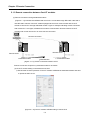
5.1.3 Remote connection between Cnet I/F modules
(1) Remote connection through dedicated modem
[Figure 5.1.11] indicates that XG5000 and local PLC is connected through RS-232C cable and in
case RS-232C channel of Cnet I/F module equipped at local PLC communicates with Cnet I/F
module of remote PLC through dedicated modem. Figure is example indicating remote connection
with remote PLC. Like figure, XG5000 uses modem communication function between Cnet I/F
modules and control remote PLC by using remote connection.
Remote connection
Remote server
Remote client
Dedicated modem
Dedicated line
Dedicated modem
[Figure 5.1.11] remote connection between Cnet I/F modules
Remote connection sequence by dedicated modem is as follows.
(a) Cnet I/F module setting connected at remote PLC
1) Set RS-232C channel operation of Cnet I/F module at XG5000 as dedicated modem and have
it operate as XGT server.
[Figure 5.1.12] Cnet I/F module XG5000 setting of remote PLC
5-8
Chapter 5 Remote Connection
(b) Cnet I/F module setting connected at local PLC
1) Converts local connected PLC to Stop mode
Note
Basic parameter of remote server connected through XG5000 should be set as server. In
case of remote client, it should be set as P2P client.
In case there are many communications, if you try to remote connection, you may fail. Be
sure to convert local PLC to stop mode and stop communication before remote connection.
(c) XG5000 setting
1) Set active mode of RS-232C of Cnet I/F module at XG5000 as Use P2P settings.
2) Set modem type of Cnet I/F module (RS-232C) as dedicated modem.
[Figure 5.1.13] Cnet I/F module XG5000 setting of local PLC
3) XG5000
a) Execute XG5000 and select “Online – Connection Settings” and set connection method.
Select Type as RS-232C and communication channel. This is same in case of local
connection.
[Figure 5.1.14] XG5000 remote connection setting screen
5-9
Chapter 5 Remote Connection
b) Select depth as remote 1 and click “Settings” for detail setting. In the detail window, set
station number. AS for station number, input station number set in Cnet I/F module to
execute remote connection. Figure is case Cnet station number is set as 1.
[Figure 5.1.15] XG5000 remote 1 connection setting screen
c) XG5000 tries remote connection and in case remote connection is complete, online related
function is activated.
d) In this case, remote 1 connection is complete, it is same status with where it is connected by
RS-232C cable. Here you can use all functions of online menu.
e) In case you want to disconnect remote connection, select disconnect at online menu.
Disconnection menu box shows and remote connection is disconnected.
In case disconnection is done normally, Cnet I/F module and XG5000 are converted into
initial mode. In case of reconnection, retry from (a) for reconnection.
f) In case of optical modem, wireless modem other than dedicated modem, communication
media is only different, method of remote connection is same.
g) [Figure 5.1.16] indicates remote connection by wireless modem. As for connection method, it
is same with method of remote connection between Cnet I/F module by using communication.
In case of using wireless modem, 1:N remote connection where there are many Cnet I/F
module is also available.
Remote connection
Remote Cent
Wireless modem
Wireless modem
[Figure 5.1.16] remote connection by using wireless modem
5-10
Chapter 5 Remote Connection
(2) Remote connection by RS-422/485
[Figure 5.1.17] indicates XG5000 and local PLC is connected into CPU module by RS-232C cable,
in case RS-422/485 channel of Cnet I/F module connected at local PLC communicates, it is figure
indicating remote connection example to remote PLC. Like figure, XG5000 can control program of
remote PLC by remote connection through remote connection function between Cnet I/F modules.
Remote server
●
Remote server
●
●
Remote client
Remote server
[Figure 5.1.17] Remote connection in case of RS-422/485 communication
Note
Basic parameter of remote server connected through XG5000 should be set as server, in case of
remote client, it should be set P2P client.
If you try remote connection when there is many communications, connection may fail. You
should convert PLC as Stop mode and stop communication before remote connection.
Remote connection sequence by using dedicated modem is as follows.
(a) Set basic parameter of remote server as XGT server.
(b) Convert local connected PLC into Stop mode.
(c) Execute XG5000 and select “Online – Connection settings” and set connection method. And
select connection method RS-232C and communication channel. This is same with case of local
connection. At this time, you should set station number of remote server to connect.
5-11
Chapter 6 Server function and P2P service
Chapter 6 Server function and P2P service
6.1 Server Modbus Service
Dedicated service is built-in service in Cnet I/F module. Without specific program at PLC, you can
read or write information and data from PC and other device. It acts as server at communication
network and if read, write request conforming XGT dedicated protocol or Modbus protocol come, it
responds.
To use dedicated service, select operation mode about channel used as server among channel 1,
channel of Cnet, when setting standard communication setting.
It supports XGT server and Modbus server and Modbus server responds about RTU and ASCII
type.
Since each channel of Cnet I/F module acts independently, you can set as other type server. For
normal operation check and diagnosis of dedicated service, refer to Chapter 9 Diagnosis.
6-1
Chapter 6 Server function and P2P service
6.1.1 XGT dedicated server
It is used in case of communication between our products by our dedicated service, all characters
are configured as ASCII code. In case of using multi drop, up to 32 stations can be connected. In
case of setting station number, duplicated station number should not be set. In case of using multi
drop, communication speed/stop bit/parity bit/data bit of all Cnet I/F module in network should be
same. For more detail protocol, refer to “chapter 7 XGT dedicated protocol”.
6.1.2 Modbus server
It is used in case partner device acts as Modbus client.
ASCII mode and RTU mode of Modbus are all supported. You can define in standard settings
active mode.
[Figure 6.1.1] Modbus server standard settings screen
Modbus instruction and response data max. number which is supported by Modbus RTU/ASCII
driver are as follows.
Other client device should request in the range of the following table.
6-2
Chapter 6 Server function and P2P service
Code
Purpose
Address
Max. no. of response data
01
Read Coil Status
0XXXX
2000 Coils
02
Read Input Status
1XXXX
2000 Coils
03
Read Holding Registers
4XXXX
125 Registers
04
Read Input Registers
3XXXX
125 Registers
05
Force Single Coil
0XXXX
1 Coil
06
Preset Single Register
4XXXX
1 Register
15
Force Multiple Coils
0XXXX
1968 Coils
16
Preset Multiple Registers
4XXXX
120 Registers
[Table 6.1.1] Modbus instruction code
About request per above code, you should set area about XGB PLC memory. At ‘Modbus Settings
of Cnet active mode’ window, if you click “Modbu Settings” button which is activated when
selecting Modbus ASCII server/RTU server, the following setting window shows.
[Figure 6.1.2] Modbus server memory settings window
Meaning of each setting item is as follows.
Item
Meaning
Reference
Bit read area Address
Address of XGB relevant to digital Input area
Bit address
Bit write area Address
Address of XGB relevant to digital output area
Bit address
Word read area Address
Address of XGB relevant to analog input area
Word address
Word write area Address
Address of XGB relevant to analog output area
Word address
[Table 6.1.2] Modbus area meaning
In case of IEC type, use IEC type address value
Address value of each item is base address of each area.
The setting of above screen is the situation of allocating bit reading area from M0000 (bit) and
Word writing area from D0000 (word).
Base address input value should be in XGB series internal device area.
Since address of Modbus 1~9999 (decimal number), size of bit IO area is 9999/8=1249.875 byte
(Namely 1249, byte should be integer unit).
Also size of word IO area is 9999*2=19998 byte.
In case the user set 0 as base address of bit output (0XXXX) area, Modbus bit area 00001
th
th
th
corresponds 0 byte 0 bit, 00002 corresponds 0 byte first bit.
6-3
Chapter 6 Server function and P2P service
6.2 P2P Service
6.2.1 General
P2P service means acting client operation of communication module. P2P instructions available at
Cnet I/F module are 4 (Read/Write/Send/Receive).
Registration and edit of P2P service is executed in XG5000, each P2P parameter consists of max.
32 P2P block.
The following figure is example of P2P parameter setting window of XG5000.
[Figure 6.2.1] P2P parameter setting example
Note
Note 1) P2P 01 is fixed allocated at built-in communication, P2P 02 for first communication module,
P2P 03 for second communication. So slot number should be correct.
6-4
Chapter 6 Server function and P2P service
6.2.2 P2P parameter configuration
To use P2P service, the user executes the setting for the wanted operation at the P2P
parameter window. Like the following figure, P2P parameter consists of three information.
[Figure 6.2.2] P2P parameter configuration screen
1) P2P channel
P2P channel setting defining communication protocol of P2P service to execute
XGT/Modbus available
Each channel is independent. It is applied when active mode is “Use P2P settings”
2) P2P block
Setting P2P block of 32 acting independently
3) User frame definition
User frame definition registration
6-5
Chapter 6 Server function and P2P service
6.2.3 Channel information
Built-in Cnet I/F function provides two fixed communication channel as fixed P2P 1.
Cnet I/F module are allocated P2P 2 and P2P 3 according to equipment sequence and
communication channel supports only one channel.
At Built-in Cnet I/F, you can define driver type for P2P service about each.
If you select P2P channel at P2P setting window, like the following, P2P channel setting window
shows. If you select P2P driver to use, setting is complete.
[Figure 6.2.3] P2P channel setting screen
Driver
Meaning
None
Not using P2P service
User frame definition
XGT client
In case of transmitting/receiving user frame definition
Select in case of executing read, write of XGT memory.
Select in case of acting as Modbus client, using ASCII mode
Select in case of acting as Modbus client, using RTU mode.
Modbus ASCII client
Modbus RTU client
[Table 6.2.1] Driver table
About communication channel, in case of selecting P2P driver as XGT or Modbus, user frame
definition can not be used.
6-6
Chapter 6 Server function and P2P service
6.2.4 Block information
If you select P2P block of each parameter at P2P parameter setting window, P2P block setting
window shows.
P2P Channel
P2P Block
[Figure 6.2.4] P2P block setting screen
You can set up to 32 independent blocks. If you select temporary block, you can designate each
block operation by selecting instruction.
[Figure 6.2.5] P2P instruction screen
6-7
Chapter 6 Server function and P2P service
6.3 XGT Client Service
When communicating by using XGT protocol, XGT client requests read or write data from server and
XGT server analyses received data from client then if received frame is fit to XGT protocol specification,
processes requested instruction with ACK response, or is not fit to XGT protocol specification, transmits
NAK response with error code to the XGT client.
6.3.1 Channel Setting
Cnet I/F module can set the driver type for P2P service. For P2P channel acts as client, active mode of
basic setting must defined “Use P2P”.
[Figure 6.3.1] P2P Channel setting
6-8
Chapter 6 Server function and P2P service
6.3.2 P2P Block Setting
After set the P2P channel as XGT client, you can set the P2P block.
Meaning of each item is as follows.
No
Item
1
Channel
2
P2P function
Setting
Description
Driver will be changed by P2P channel setting
1. READ: Select if read the data from destination station.
2. WRITE: Select if write the data to destination station.
1. Enter the time of data transmission by using special flag or
bit contact
2. XGK type: F0090(20ms cycle), M00001
2. XGI type: _T20MS(20ms cycle), %MX01
1. Single: Read or write max. four data of memory area to
destination station. Ex) M01, M10, M20, M30
2. Continuous: Read or write continuous data to destination
station Ex) M01~M10
1. Command type is single
- BIT, 1BYTE, 2BYTE, 4BYTE, 8BYTE
2. Command type is continuous
- 1BYTE, 2BYTE, 4BYTE, 8BYTE
3
Conditional flag
4
Command type
5
Data type
6
No. of variables
1. It is activate when command type is single. Select number
of data to transmission.
2. It will be fixed 1 when command type is continuous
7
Data size
1. It is activate when command type is continuous. Setting
range is 1~120byte. (In case of data type is 1BYTE)
8
Detestation station
number
1. It means destination station number and setting range is
0~31.
Setting
1. P2P function is READ
1) Read area: Device area of data saved in destination
station(server)
2) Save area: Device area of self station to save the data
2. P2P function is WRITE
1) Read area: Device area of data saved in self station
2) Save area: Device area of destination station area to
save the data
9
6-9
Chapter 6 Server function and P2P service
6.3.3 Parameter Write
After completed the P2P block setting, download the parameter to CPU.
Select [Online]→[Write] on the menu, click [OK] in the parameter download window. After download is
complete, parameter will be right applied.
[Figure 6.3.2] Parameter write
6.3.4 Enable Link
After completed the parameter download, user must enabling the P2P service. If user complete the
parameter download but do not enabling the P2P(IEP), P2P block will not work.
Select [Online]→[Communication Module Setting]→[Enable Link] and check the P2P(EIP) to use, then
P2P will be activated.
6-10
Chapter 6 Server function and P2P service
[Figure 6.3.3] Enable P2P Link
6.3.5 Diagnosis
User can check the normal operation to using diagnosis feature.
Select [Online]→[Communication module setting]→[System diagnosis]. Right click on the module to check
and select frame moniter or status by service. Then user can check the communication status.
For more information, please refer to the Chapter 10 Diagnosis.
6-11
Chapter 6 Server function and P2P service
6.4 Modbus Client Service
Modbus protocol is a standardized open protocol for client-server communication. It operates send/receive
data by function code. Device to device communication using Modbus protocol, use client-server feature to
handle only one client.
6.4.1 Channel Setting
Cnet I/F module can set the driver type for P2P service. For P2P channel acts as client, active mode of
basic setting must defined “Use P2P”.
[Figure 6.4.1] P2P Channel setting
6-12
Chapter 6 Server function and P2P service
6.4.2 P2P Block Setting
The operation using Modbus RTU/ASCII client has read function that read the data from destination
station and write function that write the data to destination station. Modbus RTU/ASCII client block
setting is as follows.
No
Item
1
Channel
2
P2P function
Setting
Description
Driver will be changed by P2P channel setting
1. READ: Select if read the data from destination station.
2. WRITE: Select if write the data to destination station.
1. Enter the time of data transmission by using special
flag or bit contact
2. XGK type: F0090(20ms cycle), M00001
2. XGI type: _T20MS(20ms cycle), %MX01
1. Single: Read or write max. four data of memory
area to destination station. Ex) M01, M10, M20,
M30
2. Continuous: Read or write continuous data
to destination station Ex) M01~M10
3
Conditional flag
4
Command type
5
Data type
Data type can be set BIT or WORD
Data size
▷It is activate when command type is continuous.
1. In case of P2P function is READ
1) Modbus RTU client
(1) BIT: 1~2000
(2) WORD: 1~120
2) Modbus ASCII client
(1) BIT: 1~976
(2) WORD: 1~61
2. In case of P2P function is WRITE
1) Modbus RTU client
(1) BIT: 1~1968
(2) WORD: 1~120
2) Modbus ASCII client
(1) BIT: 1~944
(2) WORD: 1~120
6
6-13
Chapter 6 Server function and P2P service
7
8
Detestation
station
number
1. It means destination station number and setting range is
0~31.
1. Read area: Device area of data saved in destination
station(server)
BIT Input(0x10000), WORD Input(0x30000),
2. Save area: Device area of self station to save the data
BIT Output(0x00000), WORD Output(0x40000)
Setting
6.4.3 Parameter Write
After completed the P2P block setting, download the parameter to CPU.
Select [Online]→[Write] on the menu, click [OK] in the parameter download window. After download is
complete, parameter will be right applied.
[Figure 6.4.2] Parameter write
6-14
Chapter 6 Server function and P2P service
6.4.4 Enable Link
After completed the parameter download, user must enabling the P2P service. If user complete the
parameter download but do not enabling the P2P(IEP), P2P block will not work.
Select [Online]→[Communication Module Setting]→[Enable Link] and check the P2P(EIP) to use, then
P2P will be activated.
[Figure 6.4.3] Enable P2P Link
6.4.5 Diagnosis
User can check the normal operation to using diagnosis feature.
Select [Online]→[Communication module setting]→[System diagnosis]. Right click on the module to check
and select frame moniter or status by service. Then user can check the communication status.
For more information, please refer to the Chapter 10 Diagnosis.
6-15
Chapter 6 Server function and P2P service
6.5 User Frame Definition
There are many protocols according to producer of communication device and it is impossible to supports
diverse protocols. So if the user defines protocols and writes program, Cnet I/F module allows the
communication between different devices according to defined protocol. In order to communicate with device
which doesn’t use specific protocols (XGT protocol, Modbus protocol), the user can directly define protocol
used in the device the user want to communicate and communicate. At this time, the user should define TX
and RX frame so that it meets partner device’s protocol.
[Figure 6.5.1] User frame definition
6.5.1 Structure of user definition frame
When writing frame by user definition frame, frame is divided into HEAD that start of frame, TAIL that end
of frame and BODY that data area. Each HEAD, TAIL and BODY is divided into segment. Total size of one
frame should be less than 1024 byte.
1) Structure of HEAD
Input type of segment for HEAD is divided into numerical constant and string constant.
In case of numerical constant, it means HEX value and in case of string constant, it means ASCII value.
2) Structure of TAIL
Input type of segment for HEAD is divided into numerical constant, string constant and BCC which check
frame error. Meaning of numerical constant and string constant is same with HEAD’s. BCC is segment
used for checking TRX frame error, only one can be set in the TAIL.
6-16
Chapter 6 Server function and P2P service
◆ BCC error check
It is the meaning that the numerical value and the character string which are used in HEAD are used
to be equal. BCC is the segment which is used to inspect the error of the TRX frame. It can only set
Tail. When BCC is applied, calculation about TRX frame is executed and if calculation is different,
relevant frame is ignored to improve the reliability of communication. Calculation methods about each
BCC are as follows.
Classification
General method
checking error
BCC method
Byte SUM
Adds designated data as I byte unit and uses lower byte value
Word SUM
Adds designated data as 1 word unit and uses lower word value
Byte XOR
Executes Exclusive OR calculation about designated data as 1
byte unit and uses lower byte
7bit SUM
Uses result value of byte sum except the most significant bit
7bit XOR
Uses result value of byte XOR except the most significant bit
7bit SUM#1
If result of 7 bit SUM is less than 20H, it adds 20H.
Byte SUM 2’S
COMP
Byte SUM 1’S
COMP
Method checking
error for dedicated
communication
Contents description
Takes 2’s complement about byte sum result
Takes 1’s complement about byte sum result
CRC 16
16 bit error detection method
LGIS CRC
Error detection method used for LSIS PLC
DLE AB
Error detection method used for DF1Protocol of Allen Bradley
DLE
SIEMENS
Error detection method used for Siemens 3964R communication
When setting BCC, in case of general method, the user need not set BCC setting range and
indication method and in case of dedicated method, the user should set BCC setting range and
indication method.
Item
Start
position
Start area
Segment
Contents
Determines where BCC calculation starts from among HEAD/BODY/TAIL
Determines segment location to start BCC calculation in HEAD/BODY/TAIL. 0 means
first segment will be included in the BCC calculation
Before
BCC
End
End
of
position
area
Settings
ASCII conversion
Included from start position to designated area segment
Converts result value, its size will be double
Initial value 0
Designates BCC initial value as 0. If there is no designation, initial value is FFH.
Included from start position to before BCC
Included from start position to end of designated area
6-17
Chapter 6 Server function and P2P service
3) Structure of BODY
Input type of segment which composes BODY is different according to receive and transmission.
In case of transmission, they are divided into string constant, numerical constant and fix sized variable.
Meaning of string constant and numerical constant is same with HEAD’s.
(1) Variable sized variable (in RX frame)
Part where size and contents changes are defined as variable sized variable. Variable sized variable
can be set in the BODY and after variable sized variable, the user can’t add segment. When using
variable sized variable, there should be one among HEAD, TAIL. If the user registers variable sized
variable without HEAD, TAIL, when receiving frame, there may be error according to communication
status. For reliability of communication, register one among HEAD, TAIL. (In case of Variable sized
variable of TX frame, the size is designated in P2P Block setting, so the function and characteristic is
same with Fix sized variable of RX frame.)
(2) Fix sized variable (in RX frame)
Frame part where size is fixed but contents changes are defined as Fix sized variable. It can be set in
the BODY. In case of Fix sized variable, the user can register up to 4.
TRX frame standard for user - defined communication of XGT Cnet I/F module is as follows.
Group
Frame
HEAD
TX
frame
TAIL
BODY
HEAD
TAIL
RX
frame
Segment
Numerical constant
String constant
Numerical constant
String constant
BCC
Numerical constant
String constant
Variable sized variable
Numerical constant
String constant
Numerical constant
String constant
BCC
Numerical constant
String constant
Fix sized variable
BODY
Variable sized variable
6-18
Reference
Max. 10 byte
Max. 10 byte
Max. 10 byte
Max. 10 byte
Only one BCC applicable
Max. 10 byte
Max. 10 byte
Available up to 4
Max. 10 byte
Max. 10 byte
Max. 10 byte
Max. 10 byte
Only one BCC applicable
Max. 10 byte
Max. 10 byte
Available up to 4
Fix sized variable 3, variable sized variable
1 are available
Only one variable sized variable available
After variable sized variable, adding
segment is impossible
Chapter 6 Server function and P2P service
6.5.2 Channel Setting
Cnet I/F module can set the driver type for P2P service. For P2P channel acts as client, active mode of
basic setting must defined “Use P2P”.
[Figure 6.5.2] P2P Channel setting
6.5.3 Writing transmission frame
Frame is composed of HEAD indicating start, TAIL indicating end and BODY which is data area. How to
write transmission frame is as follows.
Seq.
Setting
Setting method
Writing user frame
definition
1
1.Select User frame definition
2. Click right button of mouse and click Add Group
Creating frame
2
1.Group name is name of frame for user to write
2. Select Transmission as frame type
6-19
Chapter 6 Server function and P2P service
Seq.
Setting
Setting method
Creating frame
3
1. Check creation of frame
2. Select frame name and click right button of mouse.
3. Click Add frame to create HEAD, TAIL and BODY
4. Group Edit: when changing frame name
5. Delete Group: when deleting frame
Creating HEAD,
TAIL, BODY
4
1. After clicking Add frame, select type of frame
2. Type: HEAD, TAIL, BODY
3. Select HEAD
4. To create TAIL, BODY, repeat step 3
5. Name of frame edit window is activated when frame type is BODY
6. Available to creating many BODYs with different name
HEAD registration
5
1. Double-click HEAD. Then edit window is created.
2. Double-click edit window or click right button and select Add segment
3. Select Form
1) Numerical constant
(1) Defines numerical constant among frame
(2) Data value is always Hex (Hexadecimal)
2) String constant
(1) Registers string constant among frame
(2) Data value is always ASCII
4. Input value into Data
Ex) Form: Numerical constant
Data: 5(ENQ)
* When clicking the right button on the created segment, edit, deletion, insertion, copy, etc. are
available.
6-20
Chapter 6 Server function and P2P service
Seq.
Setting
6
TAIL registration
Setting method
1.If double-click TAIL, edit window shows
2. Setting method is same with step 5
3. Add BCC is activated after inserting segment
BODY registration
7
1.Doule-click BODY and select data form
1) Numerical constant and string constant are same as described above.
2) Variable sized variable
(1) used when frame length change
(2) available to insert up to 4 for one body
(3) ‘Assign memory’ is checked automatically
(4) Control by byte unit
3) Conversion
▶Hex to ASCII: converts the data red from PLC into ASCII and configures transmission frame
▶ASCII to Hex: converts the data red from PLC into Hex and configures transmission frame
4) Swap
▶2 Byte swap: 2 byte swap of data. Ex) 0x1234→0x3412
▶4 Byte swap: 4 byte swap of data. Ex) 0x12345678→0x78564321
▶8 Byte swap: 8 byte swap of data
6-21
Chapter 6 Server function and P2P service
6.5.4 Writing receive frame
Seq.
1
Setting
Setting method
Writing user frame
definition
1.Select User frame definition
2. Click right button of mouse and click Add Group
Creating frame
2
1.Group name is name of frame for user to write
2. Select Transmission as frame type
Creating frame
3
1. Check creation of frame
2. Select frame name and click right button of mouse.
3. Click Add frame to create HEAD, TAIL and BODY
4. Group Edit: when changing frame name
5. Delete Group: when deleting frame
Creating HEAD,
TAIL, BODY
4
1. After clicking Add frame, select type of frame
2. Type: HEAD, TAIL, BODY
3. Select HEAD
4. To create TAIL, BODY, repeat step 3
5. Name of frame edit window is activated when frame type is BODY
6. Available to creating many BODYs with different name
6-22
Chapter 6 Server function and P2P service
Seq.
Setting
Setting method
HEAD registration
5
1. Double-click HEAD. Then edit window is created.
2. Double-click edit window or click right button and select Add segment
3. Select Form
1) Meaning of each form is same as described in the transmission
4. Input value into Data
6
TAIL registration
1.If double-click TAIL, edit window shows
2. Setting method is same with step 5
3. Add BCC is activated after inserting segment
BODY registration
7
1.Doule-click BODY and select data form
1) Numerical constant and string constant are same as described above.
2) Variable sized variable
(1) used when frame length change
(2) available to insert up to 4 for one body
(3) ‘Assign memory’ is checked automatically
(4) Control by byte unit
3) Fix sized variable
(1) Used when frame size is fixed
(2) available to insert up to 4 for one body
(3) When checking ‘Assign memory’, it is available to save in the PLC memory
4) Assign memory: when setting the device area of PLC to save data
5) Conversion
▶Hex to ASCII: converts the data red from PLC into ASCII and configures transmission frame
▶ASCII to Hex: converts the data red from PLC into Hex and configures transmission frame
6) Swap
▶2 Byte swap: 2 byte swap of data. Ex) 0x1234→0x3412
▶4 Byte swap: 4 byte swap of data. Ex) 0x12345678→0x78564321
▶8 Byte swap: 8 byte swap of data
6-23
Chapter 6 Server function and P2P service
6.5.5 Parameter setting
To send and receive the user definition frame of XG-PD, the user should set the parameter by P2P block.
How to set the P2P block is as follows.
No.
Type
Block type
Meaning
1
Channel
Driver name changes according to driver set in the P2P Driver.
2
P2P
Function
1. Receive: used when receiving the frame written according to
partner’s protocol
2. Send: used when sending the frame written according to
partner’s protocol
3
Condition
al flag
1. Determines when Cent sends frame
2. It is activated when P2P function is [Send].
3. In case of XGK type Ex.: F90(20ms flag), M01
4. In case of XGI type Ex.: _T20MS(20ms flag), %MX01
1. In case of selecting [SEND] in the P2P function, select body of
transmission frame written in the user definition frame.
4
Frame
1. In case of selecting [RECEIVE] in the P2P function, select body
of receive frame written in the user definition frame.
5
Setting
1. Setting is available when [Assign memory] of Fix sized variable
and variable sized variable is checked.
2. Save area: start address to save the data received from
destination station.
6-24
Chapter 6 Server function and P2P service
6.5.6 Parameter Write
After completed the P2P block setting, download the parameter to CPU.
Select [Online]→[Write] on the menu, click [OK] in the parameter download window. After download is
complete, parameter will be right applied.
[Figure 6.5.3] Parameter write
6.5.7 Enable Link
After completed the parameter download, user must enabling the P2P service. If user complete the
parameter download but do not enabling the P2P(IEP), P2P block will not work.
Select [Online]→[Communication Module Setting]→[Enable Link] and check the P2P(EIP) to use, then
P2P will be activated.
[Figure 6.5.4] Enable P2P Link
6-25
Chapter 6 Server function and P2P service
6.5.8 Diagnosis
User can check the normal operation to using diagnosis feature.
Select [Online]→[Communication module setting]→[System diagnosis]. Right click on the module to check
and select frame moniter or status by service. Then user can check the communication status.
For more information, please refer to the Chapter 10 Diagnosis.
6-26
Chapter 6 Server function and P2P service
6.6 UDATA Instruction
6.6.1 SEND_UDATA [IEC]
SEND_UDATA
Availability
Flags
User defined data send
XGI, XGR
-
Function Block
Description
Input
REQ: requires to execute the function block
BASE : base number
SLOT: slot number
CH: channel(1 or 2)
DATA: data area to send
SIZE: data size to send
Output
DONE: maintains 1 after operation
STAT: completion and ERR info
(a) Function
1) SEND_UDATA instruction sends user defined data(UDATA).
2) BASE and SLOT should input a base and the slot number that CNET module was
attached to now.
3) CH means a channel number and must set 1 or 2
4) DATA must be declared only ARRAY OF BYTE type.
5) Array size is 1 ~ 1024 byte.
6) Save to transmit buffer as number as SIZE from DATA[0]. (Limit of data size is 1024 at
once)
7) If 1 is output by Done and STAT, it accomplished normally and If an error is produced,
state information
is displayed by STAT
6-27
Chapter 6 Server function and P2P service
(b) Error
STAT
Message
Description
0
Initial state
Initial state before instruction operation
1
No error
normal operation
2
Module setting error
Module is not installed or CNET module trouble
3
Channel setting error
Input range(1, 2) is exceeded
4
Array size error
Transmit data size exceed 1024
5
Parameter setting
CNET module’s parameter is not set as User defined or link
error
enable is not set
Instruction timeout
No response from module or maximum scan time is
error
exceeded(10 scan)
Version mismatch
XGI CPU version is under V3.9, XGR CPU version is under
error
V2.6 or CNET module version is under V3.2
6
7
(c) Program example
Order to send up to 1,024 Byte with CNET module attached to BASE, SLOT
6-28
Chapter 6 Server function and P2P service
6.6.2 RCV_UDATA [IEC]
RCV_UDATA
Availability
Flags
User defined data send
XGI, XGR
-
Function Block
Description
Input
REQ: requires to execute the function block
BASE : base number
SLOT: slot number
CH: channel(1 or 2)
DATA: data area to save
Output
DONE: maintains 1 after operation
STAT: completion and ERR info
SIZE: received data size
(a) Function
1) RCV_UDATA instruction saves received user defined data(UDATA) from CNET module.
2) BASE and SLOT should input a base and the slot number that CNET module was
attached to now.
3) CH means a channel number and must set 1 or 2
4) DATA must be declared only ARRAY OF BYTE type.
5) Array size is 1 ~ 1024 byte.
6) Save to transmit buffer as number as SIZE from DATA[0]. (Limit of data size is 1024 at
once)
7) If 1 is output by Done and STAT, it accomplished normally and If an error is produced,
state information
is displayed by STAT
(b) Error
STAT
Message
Description
0
Initial state
Initial state before instruction operation
1
No error
normal operation
2
Module setting error
Module is not installed or CNET module trouble
3
Channel setting error
Input range(1, 2) is exceeded
4
Array size error
Transmit data size exceed 1024
5
Parameter setting
CNET module’s parameter is not set as User defined or link
error
enable is not set
Instruction timeout
No response from module or maximum scan time is exceeded(10
error
scan)
Version mismatch
XGI CPU version is under V3.9, XGR CPU version is under V2.6
error
or CNET module version is under V3.2
6
7
6-29
Chapter 6 Server function and P2P service
6.6.3 SEND_DTR [IEC]
SEND_DTR
Availability
Flags
DTR signal send
XGI, XGR
-
Function Block
Description
Input
REQ: requires to execute the function block
BASE : base number
SLOT: slot number
CH: channel(1 or 2)
DTR: 0 or 1
Output
DONE: maintains 1 after operation
STAT: completion and ERR info
(a) Function
1) SEND_DTR instruction send DTR(Data Terminal Ready) signal that means
communication ready complete.
2) If 1 is output by Done and STAT, it accomplished normally and If an error is produced,
state information
is displayed by STAT
(b) ERROR
STAT
Message
Description
0
Initial state
Initial state before instruction operation
1
No error
normal operation
2
Module setting error
Module is not installed or CNET module trouble
3
Channel setting error
Input range(1, 2) is exceeded
4
DTR setting error
Input range(0, 1) is exceeded
5
Parameter setting error
CNET module’s parameter is not set as User defined or link
enable is not set
6
Instruction timeout error
No response from module or maximum scan time is
exceeded(10 scan)
7
Version mismatch error
XGI CPU version is under V3.9, XGR CPU version is under
V2.6 or CNET module version is under V3.2
6-30
Chapter 6 Server function and P2P service
6.6.4 SEND_RTS [IEC]
SEND_RTS
Availability
Flags
RTS signal send
XGI, XGR
-
Function Block
Description
Input
REQ: requires to execute the function block
BASE : base number
SLOT: slot number
CH: channel(1 or 2)
RTS: 0 or 1
Output
DONE: maintains 1 after operation
STAT: completion and ERR info
(a) Function
1) SEND_DTR instruction send DTR(Data Terminal Ready) signal that means
communication ready complete.
2) If 1 is output by Done and STAT, it accomplished normally and If an error is produced,
state information
is displayed by STAT
(b) ERROR
STAT
Message
Description
0
Initial state
Initial state before instruction operation
1
No error
normal operation
2
Module setting error
Module is not installed or CNET module trouble
3
Channel setting error
Input range(1, 2) is exceeded
4
RTS setting error
Input range(0, 1) is exceeded
5
Parameter setting error
CNET module’s parameter is not set as User defined or link
enable is not set
6
Instruction timeout error
No response from module or maximum scan time is
exceeded(10 scan)
7
Version mismatch error
XGI CPU version is under V3.9, XGR CPU version is under
V2.6 or CNET module version is under V3.2
6-31
Chapter 6 Server function and P2P service
6.6.5 SNDUDATA [MK]
Area Available
Instruction
Flag
Step
PM
F
L
T
C
S
Z
D.x R.x Const U N
D
Error
Zero
Carry
R
K
(F110) (F111) (F112)
sl
-
-
-
-
-
-
-
-
-
O
-
-
-
-
S1
O
-
O
-
-
-
O
-
-
O
O O
O
O
SNDUDATA S2
O
-
O
-
-
-
O
-
-
-
O O
O
O
S3
O
-
O
-
-
-
O
-
-
-
O O
O
O
D
O
-
O
-
-
-
O
-
-
-
O O
O
O
4~7
O
-
-
COMMAND
SNDUDATA
SNDUDATA
sl
S1
S2
S3
D
[Area Setting]
Operand
sl
S1
S2
S3
D
Description
Base and slot number
Channel (1 or 2)
Data area to send
Data size to send (maximum 1024 Byte)
Temporary device that used in instruction
Data type
WORD
WORD
WORD
WORD
WORD
[Flag Setting]
Flag
Error
Description
If sl value is not matched with CNET module installed.
Device
Number
F110
(a) SNDUDATA
1) SNDUDATA instruction sends user defined data(UDATA).
2) sl is base and slot number of CNET module installed.
3) S1 is channel number (1 or 2).
4) S2 is start device to send UDATA
5) S3 is size of UDATA, instruction sends the number of S3 from S2(Maximum 1024 Byte).
6) D is temporary device area to save instruction information. Initial value is 0 and If user
change that value, instruction is not operated normally.
CPU Device
Data size
Information
D
WORD
State code
D+1
WORD
Reserved area
D+2
WORD
(Prohibition on Use)
D+3
WORD
6-32
Chapter 6 Server function and P2P service
(b) Error
1) If sl value is not matched with CNET module installed, set error flag(F110).
(a)
(c) State Information
State
code
00
01
02
03
04
State
06
Initial state
Done
Modlue setting error
Channel setting error
Data size setting error
Communication
parameter setting error
Timeout error
07
Verseion mismatch
05
Information
Before excute instruction
Instruction excute complete
If sl value is not matched with CNET module installed
S1 value is not 1 or 2
Size if data to send exceeds range(0~1024)
If parameter of CNET module is not set as user defined
data, or when Link enable is not set
No response casue of abnormal CNET module
CNET OS version is below V3.2
(If CPU version is below V4.2, program download in not
operated )
(d) Program Example
1) If Input signal REQ, Order to send up to SIZE with CNET module attached to BASE,
SLOT
Remark
(1) Devices D+1 ~ D+3 set in operand D are the areas to be saved with instruction information. So users
must not change that areas. If change that areas, instruction is not operated normally.
6-33
Chapter 6 Server function and P2P service
6.6.6 RCVUDATA [MK]
Area Available
Flag
Instruction
Step
Con
PMK
F
L
T
C
S
Z
D.x R.x
U
N
D
Error
Zero
Carry
R
st
(F110) (F111) (F112)
sl
-
-
-
-
-
-
-
-
-
O
-
-
-
-
S1
O
-
O
-
-
-
O
-
-
O
O
O
O
O
SNDUDATA D1
O
-
O
-
-
-
O
-
-
-
O
O
O
O
D2
O
-
O
-
-
-
O
-
-
-
O
O
O
O
D3
O
-
O
-
-
-
O
-
-
-
O
O
O
O
4~7
O
-
-
COMMAND
RCVUDATA
RCVUDATA
sl
S1
D1
D2
D3
[Area Setting]
Operand
sl
S1
D1
D2
D3
Description
Base and slot number
Channel (1 or 2)
Data area to receive
Data size to receive (maximum 1024 Byte)
Temporary device that used in instruction
Data type
WORD
WORD
WORD
WORD
WORD
[Flag Setting]
Flag
Error
Description
If sl value is not matched with CNET module installed.
(b) RCVUDATA
1)
2)
3)
4)
5)
6)
Device
Number
F110
RCVUDATA instruction receives user defined data(UDATA).
sl is base and slot number of CNET module installed.
S1 is channel number (1 or 2).
D1 is start device to save UDATA
D2 is size of UDATA and unit is Byte.
D3 is temporary device area to save instruction information. Initial value is 0 and If user
change that value, instruction is not operated normally.
CPU Device
Data size
Information
D3
WORD
State code
D3+1
WORD
Reserved area
D3+2
WORD
(Prohibition on Use)
D3+3
WORD
(c) Error
1) If sl value is not matched with CNET module installed, set error flag(F110).
6-34
Chapter 6 Server function and P2P service
(d) State Information
State code
00
01
02
03
04
06
State
Initial state
Done
Modlue setting error
Channel setting error
No data received
Communication
parameter setting
error
Timeout error
07
Verseion mismatch
05
Information
Before excute instruction
Instruction excute complete
If sl value is not matched with CNET module installed
S1 value is not 1 or 2
No data received
If parameter of CNET module is not set as user defined data,
or when Link enable is not set
No response casue of abnormal CNET module
CNET OS version is below V3.2
(If CPU version is below V4.2, program download in not
operated )
(e) Program Example
(f) 1) If Input signal M00001, Order to receive up to SIZE with CNET module attached to BASE, SLOT
Remark
(1) Devices D3+1 ~ D3+3 set in operand D3 are the areas to be saved with instruction information. So
users must not change that areas. If change that areas, instruction is not operated normally.
(2) Maximum size of data received is 1024 Byte and device number set as D2 must smaller than (end
area of that device – 1024 Byte).
6-35
Chapter 6 Server function and P2P service
6.6.7 SENDDTR [MK]
Area Available
Flag
Instruction
Step
Con
PMK
F
L
T
C
S
Z
D.x R.x
U
N
D
Error
Zero
Carry
R
st
(F110) (F111) (F112)
sl
-
-
-
-
-
-
O
-
-
O
-
-
-
-
S1
O
-
O
-
-
-
O
-
-
O
O
O
O
O
S2
O
-
O
-
-
-
O
-
-
O
O
O
O
O
D
O
-
O
-
-
-
O
-
-
-
O
O
O
O
SNDDTR
4~7
O
-
-
COMMAND
SENDDTR
SENDDTR
sl
S1
S2
D
[Area Setting]
Operand
Description
Data type
WORD
WORD
WORD
WORD
Base and slot number
Channel (1 or 2)
DTR (0 or 1)
Temporary device that used in instruction
sl
S1
S2
D
[Flag Setting]
Flag
Error
Description
If sl value is not matched with CNET module installed.
Device Number
F110
(a) Function
1) SENDDTR instruction sends DTR(Data Terminal Ready) signal.
2) sl is base and slot number of CNET module installed.
3) S1 is channel number (1 or 2).
4) S2 is DTR value (0 or 1).
5) D is temporary device area to save instruction information. Initial value is 0 and If user
change that value, instruction is not operated normally.
CPU Device
Data size
Information
D
WORD
State code
D+1
WORD
Reserved area
D+2
WORD
(Prohibition on Use)
D+3
WORD
(b) Error
1) If sl value is not matched with CNET module installed, set error flag(F110).
(c) State Information
6-36
Chapter 6 Server function and P2P service
State code
State
00
01
Initial state
Done
Modlue setting
error
Channel setting
error
DTR level setting
error
Communication
parameter setting
error
Timeout error
02
03
04
05
06
07
Verseion
mismatch
Information
Before excute instruction
Instruction excute complete
If sl value is not matched with CNET module installed
S1 value is not 1 or 2
S2 DTR setting value is not 0 or 1
If parameter of CNET module is not set as user defined data, or
when Link enable is not set
No response casue of abnormal CNET module
CNET OS version is below V3.2
(If CPU version is below V4.2, program download in not
operated )
(d) Program Example
1) If Input signal M00002, Order to send DTR(Data Terminal Ready) up to SIZE with CNET
module attached to BASE, SLOT
(g)
(h)
Remark
(1) Devices D+1 ~ D+3 set in operand D are the areas to be saved with instruction information. So users
must not change that areas. If change that areas, instruction is not operated normally.
6-37
Chapter 6 Server function and P2P service
6.6.8 SENDRTS [MK]
Area Available
Flag
Instruction
Step
Con
PMK
F
L
T
C
S
Z
D.x R.x
U
N
D
Error
Zero
Carry
R
st
(F110) (F111) (F112)
sl
-
-
-
-
-
-
O
-
-
O
-
-
-
-
S1
O
-
O
-
-
-
O
-
-
O
O
O
O
O
S2
O
-
O
-
-
-
O
-
-
O
O
O
O
O
D
O
-
O
-
-
-
O
-
-
-
O
O
O
O
SNDDTR
4~7
O
-
-
COMMAND
SENDRTS
SENDRTS
sl
S1
S2
D
[Area Setting]
Operand
sl
S1
S2
D
Description
Base and slot number
Channel (1 or 2)
RTS (0 or 1)
Temporary device that used in instruction
Data type
WORD
WORD
WORD
WORD
[Flag Setting]
Flag
Error
Description
If sl value is not matched with CNET module installed.
Device
Number
F110
(a) Function
1) SENDRTS instruction sends RTS(Request To Send) signal.
2) sl is base and slot number of CNET module installed.
3) S1 is channel number (1 or 2).
4) S2 is RTS value (0 or 1).
5) D is temporary device area to save instruction information. Initial value is 0 and If user
change that value, instruction is not operated normally.
CPU Device
Data size
Information
D
WORD
State code
D+1
WORD
Reserved area
D+2
WORD
(Prohibition on Use)
D+3
WORD
(b) Error
1) If sl value is not matched with CNET module installed, set error flag(F110).
6-38
Chapter 6 Server function and P2P service
(c) State Information
State code
00
01
02
03
06
State
Initial state
Done
Modlue setting error
Channel setting error
DTR level setting
error
Communication
parameter setting
error
Timeout error
07
Verseion mismatch
04
05
Information
Before excute instruction
Instruction excute complete
If sl value is not matched with CNET module installed
S1 value is not 1 or 2
S2 RTS setting value is not 0 or 1
If parameter of CNET module is not set as user defined data,
or when Link enable is not set
No response casue of abnormal CNET module
CNET OS version is below V3.2
(If CPU version is below V4.2, program download in not
operated )
(d) Program Example
1) If Input signal M00003, Order to send RTS(Request to send) up to SIZE with CNET
module attached to BASE, SLOT
Remark
(1) Devices D+1 ~ D+3 set in operand D are the areas to be saved with instruction information. So users
must not change that areas. If change that areas, instruction is not operated normally.
6-39
Chapter 7 XGT Dedicated Protocol
Chapter 7 XGT Dedicated Protocol
7.1 XGT Dedicated Protocol
XGT series dedicated protocol communication is function executing communication by our dedicated protocol.
User can configure the intended communication system between our products without special setting by using
reading/writing data of internal device area and monitoring function.
Dedicated protocol function supported by XGB is as follows.
• Device individual/continuous read
• Device individual/continuous write
• Monitor variable registration
• Monitor execution
• 1:1 connection (Our link) system configuration
Note
XGB’s built-in communication function supports Cnet communication without any separate Cnet
I/F module. It must be used under the following instructions.
1) Channel 0 of XGB’s main unit supports 1:1 communication only. For 1:N system having masterslave Format, use RS-485 communication in channel 1 or XGB’s main unit with XGL-C41A module
connected. XGL-C41A module supports RS-422/485 protocol.
2) RS-232C communication cable for XGB’s main unit is different from RS-232C cable for
XG5000 in pin arrangement and from the cable for Cnet I/F module, too. The cable can’t be
used without any treatment. For the detailed wiring method, refer to configuration of
respective communication.
3) It’s possible to set baud rate type and station No. in XG5000.
7-1
Chapter 7 XGT Dedicated Protocol
7.1.1 Frame structure
(1) Base format
(a) Request frame (external communication device→XGB)
Header
(ENQ)
Station
number
Command
Command
type
Structurized data area
Tail
(EOT)
Frame check
(BCC)
(b) ACK response frame (XGB→external communication device, when receiving data normally)
Header
(ACK)
Station
number
Command
Command
type
Structurized data area or Tail
Null code
(ETX)
Frame check
(BCC)
(c) NAK response frame (XGB→external communication device when receiving data abnormally)
Header
(NAK)
Station
number
Command
Command
type
Error code ( ASCII 4 Byte )
Tail
(ETX)
Frame check
(BCC)
Note
1) The numerical data of all frames are ASCII codes equal to hexadecimal value, if there’s no clear
statement.
The terms in hexadecimal are as follows.
• Station No.
• When the main command is R(r) or W (w) and the command type is numerical (means a data type)
• All of the terms indicating size of all data in the formatted data area.
• Monitoring registration and command registration number of execution commands.
• All contents of data
2) If it is hexadecimal, H is attached in front of the number of frames like H01, H12345, H34, H12,
and H89AB.
3) Available frame length is maximum 256 bytes.
4) Used control codes are as follows.
Codes
Hex value
Name
Contents
ENQ
H05
Enquire
Request frame initial code
ACK
H06
Acknowledge
ACK response frame initial code
NAK
H15
Not
Acknowledge
NAK response frame initial code
EOT
H04
End of Text
Request frame ending ASCII code
ETX
H03
End Text
Response frame ending ASCII code
5) If the command is small letter (r), BCC value is added in check frame. The other side capital
letter (R), BCC value is not added in check frame.
7-2
Chapter 7 XGT Dedicated Protocol
(2) Command frame sequence
▪ Sequence of command request frame
Stati
on
No.
ENQ
Comma
nd
Formatted data
EOT
BCC
Station
Command
No.
(PLC ACK response)
Formatted data
ETX
BCC
Formatted data
ETX
BCC
ACK
NAK
Station
Command
No.
(PLC NAK response)
7.1.2 List of commands
List of commands used in dedication communication is as shown below.
Command
Classification
Items
Reading
device
Writing
device
Main command
Code
Command type
ASCII code
Code
ASCII code
Individual r(R)
H72
(H52)
SS
5353
Continuous r(R)
H72
(H52)
SB
5342
Individual w(W)
H77
(H57)
SS
5353
Continuous w(W)
H77
(H57)
SB
5342
Classification
Treatment
Reads direct variable of Bit, Byte, Word, Dword, Lword type.
Read direct variable of Byte, Word, Dword, Lword with
block unit
(Bit continuous read is not allowed)
Write data of Bit, Byte, Word, Dword, Lword at direct
variable
Write data of Byte, Word, Dword, Lword at direct
variable with block unit
(Bit continuous read is not allowed)
Command
Main command
Register No
Item
Code
ASCII code
Monitoring
variable
register
x(X)
H78
(H58)
H00~H0F
Execution of
monitoring
y(Y)
H79
(H59)
H00~H0F
Treatment
Register device to monitor.
Execute registered device to monitor.
Note
• It identifies capitals or small letters for main commands, but not for the others.
7-3
Chapter 7 XGT Dedicated Protocol
7.1.3 Data type
It’s possible to read and write device in built-in communication. When device is used, be aware of data type.
• Available types of device
- XBM-DXXXS and XBC-DXXXH
Device
“S” type range
“H” type range
Size (Word)
Remark
P
P0 – P127
P0 – P1023
1024
Read/Write/Monitor available
M
M0 – M255
M0 – M1023
1024
Read/Write/Monitor available
K
K0 – K2559
K0 – K4095
4096
Read/Write/Monitor available
F
F0 – F255
F0 – F1023
1024
Read/Monitor available
T
T0 – T255
T0 – T1023
1024
Read/Write/Monitor available
C
C0 – C255
C0 – C1023
1024
Read/Write/Monitor available
L
L0 – L1279
L0 – L2047
2048
Read/Write/Monitor available
N
N0 – N3935
N0 – N5119
5120
Read/Monitor available
D
D0 – D5119
D0 – D10239
10240
Read/Write/Monitor available
U
U00.00 – U07.31
U00.00 – U0A.31
352
Read/Write/Monitor available
Z
Z0 – Z127
Z0 – Z127
128
Read/Write/Monitor available
10240
Read/Write/Monitor available
R
-
R0 – R10239
- XEC-DXXXH
Device
Range
Size (Word)
Remark
I
%IW0.0.0 ~ %IW15.15.3
1024
Read/Write/Monitor available
Q
%QW0.0.0 ~ %QW15.15.3
1024
Read/Write/Monitor available
M
%MW0 ~ %MW8191
8192
Read/Write/Monitor available
W
%WW0 ~ %WW10239
10240
Read/Write/Monitor available
R
%RW0 ~ %RW10239
10240
Read/Write/Monitor available
F
%FW0 ~ %FW1023
1024
Read/Monitor available
K
%KW0 ~ %KW4095
4096
Read/Write/Monitor available
L
%LW0 ~ %LW2047
2048
Read/Write/Monitor available
N
%NW0 ~ %NW5119
5120
Read/Monitor available
U
%UW0.0.0 ~ %UW0.15.31
512
Read/Write/Monitor available
7-4
Chapter 7 XGT Dedicated Protocol
• When device is designated, attach ‘%’ (25H) in front of the marking characters.
(‘%’ is stands for starting of device.)
Marking
Data type
Examples
characters
Bit
X(58H)
%PX000,%MX000,%LX000,%KX000,%CX000,%TX000,%FX000 etc.
Byte
B(42H)
%PB000,%MB000,%LB000,%KB000,%CB000,%TB000,%FB000 etc.
Word
W(57H)
Dword
D(44H)
Lword
L(4CH)
%PW000,%MW000,%LW000,%KW000,%CW000,%TW000,%FW000,
%DW000 etc.
%PD000,%MD000,%LD000,%KD000,%CD000,%TD000,
%FD000,%DD000 etc.
%PL000,%ML000,%LL000,%KL000,%CL000,%TL000,
%FL000,%DL000 etc.
Note
• Timer/Counter used in bit command means contact point values.
(word command means current values.)
• Data register (D) can uses only word or byte commands.
• In byte type commands, address is doubled. For example, D1234 is addressed to ‘%DW1234’
in word type, and is addressed to ‘%DB2468’ in byte type.
7-5
Chapter 7 XGT Dedicated Protocol
7.2 Detail of Instruction
7.2.1 Individual reading of device (R(r)SS)
This is a function that reads PLC device specified in accord with memory data type. Separate device
memory can be read up to 16 at a time.
• PC request format
Format name
Header
Station No.
Command
Command
type
Number
of blocks
Device
length
Device name
Tail
Frame
check
Ex. of frame
ENQ
H20
R(r)
SS
H01
H06
%MW100
EOT
BCC
ASCII value
H05
H3230
H52(72)
H5353
H3031
H3036
H254D57313030
H04
....
1 block (setting can be repeated up to max. 16 blocks)
Item
Description
When command is lowercase(r), only one lower byte of the value resulted by adding 1
BCC
Byte each to ASCII values from ENQ to EOT is converted into ASCII and added to BCC.
For example, the BCC of the above frame is gotten as below:
H05+H32+H30+H72+H53+H53+H30+H31+H30+H36+H25+H4D+H57+H31+H30+H30+
H04 = H03A4 Therefore BCC value is A4 (ASCII value : H4134).
Number of
Blocks
Device length
(Length of
device name)
Device name
This specifies how much of the blocks composed of "[device length][device name]" are in
this request format. This can be set up to 16. Therefore, the value of [Number of blocks]
must be set between H01(ASCII value:3031)-H10(ASCII value:3030).
This indicates the number of name's characters that means device, which is allowable up
to 16 characters. This value is one of ASCII converted from hex type, and the range is
from H01(ASCII value:3031) to H10(ASCII value:3130). For example, if the device name
is %MW0, it has 4 characters to be H04 as its length. If %MW000 characters to be H06.
Address to be actually read is entered. This must be ASCII value within 16 characters,
and in this name, digits, upper/lower case, '%' is only allowable to be entered.
Note
• BCC value is low 1byte in the sum of each byte from ENQ to EOT.
• In case of making actual frame, 'H' is not attached. Because the data of frame indicates hexadecimal.
7-6
Chapter 7 XGT Dedicated Protocol
• XGB response format (ACK response)
Format name Header Station No. Command Command type
Ex. of frame ACK
H20
R(r)
SS
ASCII value H06
H3230
H52(72)
H5353
Number Number of
of blocks data
H01
H02
data
Tail
Frame
check
ETX
BCC
......
HA9F3
H3031 H3032 H41394633
H04
1 block (max. 16 blocks possible)
Item
Description
BCC
When command is lowercase(r), only one lower byte of the value resulted by
adding 1 Byte each to ASCII values from ACK to ETX is converted into ASCII and
added to BCC, and sent.
Number of data means byte number of hex type, and is converted into ASCII. This
number is determined according to data type (X,B,W) included in device name of
computer request Format.
• Number of data in accordance with its data type is as follows:
Number of
data
Data type
Available variable
Number of data
Bit(X)
%(P,M,L,K,F,T,C,D,R,I,Q,W)X
1
Byte(B)
%(P,M,L,K,F,T,C,D,R,I,Q,W)B
1
Word(W)
%(P,M,L,K,F,T,C,D,R,I,Q,W)W
2
※R area is supported at XBC-DXXXH
Data
• In data area, there are the values of hex data converted to ASCII code saved.
▪ Example 1
The fact that number of data is H04 (ASCII code value:H3034) means that there is hex data of 4
bytes in data. Hex data of 4 bytes is converted into ASCII code in data.
▪ Example 2
If number of data is H04 and the data is H12345678, ASCII code converted value of this is "31
32 33 34 35 36 37 38," and this contents is entered in data area. Name directly, highest value is
entered first, lowest value last.
7-7
Chapter 7 XGT Dedicated Protocol
• XGB response format (NAK response)
Format name
Heade
r
Station
No.
Ex. of frame
NAK
H20
R(r)
ASCII value
H15
H3230
H52(72)
Command
Error code
(Hex 2 Byte)
Tail
Frame check
SS
H1132
ETX
BCC
H5353
H31313332
H03
Command type
Item
Explanation
BCC
When command is lowercase(r), only one lower byte of the value resulted by adding 1 Byte each to
ASCII values from NAK to ETX is converted into ASCII and added to BCC.
Error code
Hex and 2 bytes (ASCII code, 4 bytes) indicate error type. Refer to Appendix 3 error codes and
countermeasures.
• Example
XGB main unit
This example supposes when 1 WORD from M20 and 1 WORD from P001 address of station No.1
are read
(At this time, it is supposed that H1234 is entered in M20, and data of H5678 is entered in P001.)
• PC request format (PC → XGB)
Comman Number of Variable
Device
Variable name
Variable name
blocks
length
length
d type
Ex. of frame ENQ H01
R(r)
SS
H02
H06
%MW020
H06
%PW001
ASCII value H05 H3031 H52(72) H5353 H3032 H3036 H254D57303230 H3036 H25505730303031
Format name Header
Station
No.
Tail
Command
EOT
H04
Frame
check
BCC
• For ACK response after execution of command (PC ← XGB)
Station
No.
Command
Command Number of Number of
type
blocks
data
Format name
Header
Ex. of frame
ASCII value
ACK H01
R(r)
SS
H06 H3031 H52(72) H5353
H02
H3032
Data
Number of
data
H02
H1234
H02
H3032 H31323334 H3032
Data
Tail
Frame check
H5678
H35363738
ETX
H03
BCC
• For NAK response after execution of command (PC ← XGB)
Format name
Header
Station No.
Command
Command type
Ex. of frame
ASCII value
NAK
H15
H01
H3031
R(r)
H52(72)
SS
H5353
7-8
Error code
Error code (2 Byte)
Error code (4 Byte)
Tail
ETX
H03
Frame check
BCC
Chapter 7 XGT Dedicated Protocol
7.2.2 Direct variable continuous reading (R(r)SB)
This is a function that reads the PLC device memory directly specified in accord with memory data type.
With this, data is read from specified address as much as specified continuously.
• PC request format
Format
name
Ex. of
frame
ASCII
value
Head
er
Station
No.
Comman
d
Comman
d type
Device length
Device
Number of data
Tail
Frame check
ENQ
H10
R(r)
SB
H06
%MW100
H05
EOT
BCC
H05
H3130
H52(72)
H5342
H3036
H254D5731
3030
H3035
H04
Item
Description
BCC
When command is lowercase(r), only one lower byte of the value resulted by adding
1 Byte each to ASCII values from ENQ to EOT is converted into ASCII and added to
BCC.
Device length
(Length of
device name)
Device name
This indicates the number of name's characters that means device, which is
allowable up to 16 characters. This value is one of ASCII converted from hex type,
and the range is from H01 (ASCII value:3031) to H10 (ASCII value:3130).
Address to be actually read is entered. This must be ASCII value within 16
characters, and in this name, digits, upper/lowercase, and '%' only are allowable to
be entered.
Note
• Number of data specifies the number to read according to the type of data. Namely, if the data type
of device is word and number is 5, it means that 5 words should be read.
• In the number of data, you can use up to 60 words (120Byte).
• Protocol of continuous reading of direct variable doesn't have number of blocks.
• Bit device continuous reading is not supported.
7-9
Chapter 7 XGT Dedicated Protocol
• XGB response format (ACK response)
Format name
Header
Station
No.
Command
Ex. of frame
ACK
H10
R(r)
ASCII value
H06
H3130
H52(72)
Number of
blocks
Number of
data
data
Tail
Frame check
SB
H01
H02
H1122
ETX
BCC
H5342
H3031
H3134
H31313232
H03
Command
type
Item
Description
It means byte number of hex type, and is converted into ASCII
Data type
Available device
Data size (Byte)
Number of data
BYTE(B)
%(P,M,L,K,F,T,C,D,R,I,Q,W)B
1
WORD(W)
%(P,M,L,K,F,T,C,D,R,I,Q,W)W
2
DWord(D)
%(P,M,L,K,F,T,C,D,R,I,Q,W)D
4
LWord(L)
%(P,M,L,K,F,T,C,D,I,Q,W)L
8
※R area is supported at XBC-DXXXH
• Example 1
When memory type included in variable name of computer request Format is W (Word), and data
number of computer request Format is 03, data number of PLC ACK response after execution of
command is indicated by H06 (2*03 = 06 bytes)Byte and ASCII code value 3036 is entered in data area.
• Example 2
In just above example, when data contents of 3 words are 1234, 5678, and 9ABC in order, actual ASCII
code converted values are 31323334 35363738 39414243, and the contents are entered in data area.
• XGB response format (NAK response)
Format name
Heade
r
Station
No.
Command
Command type
Error code
(Hex 2 Byte)
Tail
Frame check
Ex. of frame
NAK
H10
R(r)
SB
H1132
ETX
BCC
ASCII value
H15
H3130
H52(72)
H5342
H31313332
H03
Item
BCC
Error code
Description
When command is lowercase(r), only one lower byte of the value resulted by adding 1
Byte each to ASCII values from NAK to ETX is converted into ASCII and added to BCC,
and sent.
Hex and 2 bytes (ASCII code, 4 bytes) indicate error type. For the details, Refer to
Appendix 3 error codes and countermeasures.
7-10
Chapter 7 XGT Dedicated Protocol
• Example
This example supposes that 2 WORDs from M000 of station No. 10 is read
(It supposes that M000 = H1234, M001 = H5678.)
• PC request format (PC → XGB)
Format name Header
Station
No.
Command
Command
Device length
type
Device name
Number of data
Tail
Frame check
BCC
Frame (Example)
ENQ
H0A
R(r)
SB
H06
%MW000
H02
EOT
ASCII value
H05
H3041
H52(72)
H5342
H3036
H254D303030
H3032
H04
•For ACK response after execution of command (PC ← XGB)
Format name
Header
Frame (Example)
ACK
H0A
ASCII value
H06
H3041
Command
type
Number
of block
Number
of data
Data
Tail
Frame check
R(r)
SB
H01
H04
12345678
ETX
BCC
H52(72)
H5342
H3031
H3034
H3132333435363738
03
Command type
Error code
Tail
BCC
BCC
Station No. Command
•For NAK response after execution of command (PC ← XGB)
Format name
Header Station No.
Command
Frame (Example)
NAK
H0A
R(r)
SB
Error code (2 Byte)
ETX
ASCII value
H15
H3041
H52(72)
H5342
Error code (4 Byte)
H03
7-11
Chapter 7 XGT Dedicated Protocol
7.2.3 Individual writing of device (W(w)SS)
This is a function that writes the PLC device memory directly specified in accord with memory data type.
• PC request format
Format name
Header
Station No.
Command
Command
type
Number of
blocks
Device
Length
Device Name
Data
.....
Frame
Tail
check
Frame (Example)
ENQ
H20
W(w)
SS
H01
H06
%MW100
H00E2
EOT
ASCII value
H05
H3230
H57(77)
H5353
H3031
H3036
H254D57313030
H30304532
H04
BCC
1 block (setting can be repeated up to max. 16 blocks)
Item
Description
BCC
When command is lowercase(r), only one lower byte of the value resulted by adding 1
Byte each to ASCII values from ENQ to EOT is converted into ASCII and added to
BCC.
Number of blocks
This specifies how much of the blocks composed of "[device length][device name]"
are in this request Format. This can be set up to 16. Therefore, the value of [Number
of blocks] must be set between H01(ASCII value:3031)-H10 (ASCII value:3030).
Device
Length
(Name length of device)
device
Data
This indicates the number of name's characters that means device, which is allowable
up to 16 characters. This value is one of ASCII converted from hex type, and the
range is from H01 (ASCII value: 3031) to H10 (ASCII value:3130).
Address to be actually read is entered. This must be ASCII value within 16
characters, and in this name, digits, upper/lower case, and '%' only is allowable to be
entered.
If the value to be written in %MW100 area is H A, the data Format must be H000A. If
the value to be written in %MW100 area is H A, the data Format must be H000A. In
data area, the ASCII value converted from hex data is entered.
• Example 1
If type of data to be currently written is WORD, the data is H1234, ASCII code converted value of this is
"31323334" and this content must be entered in data area. Namely, most significant value must be sent
first, least significant value last.
Note
• Device data types of each block must be the same
• If data type is Bit, the data to be written is indicated by bytes of hex. Namely, if Bit value is 0,
it must be indicated by H00 (3030), and if 1, by H01 (3031).
7-12
Chapter 7 XGT Dedicated Protocol
• XGB Response format (ACK response)
Format name
Header
Station No.
Command
Command type
Tail
Frame check
Frame (Example)
ACK
H20
W(w)
SS
ETX
BCC
ASCII value
H06
H3230
H57(77)
H5353
H03
Item
BCC
Description
When command is lowercase (r), only one lower byte of the value resulted by
adding 1 Byte each to ASCII values from ACK to ETX is converted into ASCII and
added to BCC, and sent.
• XGB Response format (NAK response)
Error code
Format name
Header
Station No.
Command
Command type
Frame (Example)
NAK
H20
W(w)
SS
ASCII value
H15
H3230
H57(77)
H5353
Item
BCC
Error code
Tail
Frame check
H4252
ETX
BCC
H34323532
H03
(Hex 2 Byte)
Description
When command is lowercase(r), only one lower byte of the value resulted by adding
1 Byte each to ASCII values from NAK to ETX is converted into ASCII and added to
BCC, and sent.
Hex and 2 bytes (ASCII code, 4 bytes) indicate error type. For the details, Refer to
Appendix 3 error codes and countermeasures.
• Example
This example supposes that "HFF" is written in M230 of station No. 1.
• PC request format (PC → XGB)
Format name Header
Frame (Example) ENQ
ASCII value
H05
Station
Command Number
No. Command
type
of blocks
Device
Device Name
Data
Tail
%MW230
H254D573233
30
H00FF
EOT
H30304646
H04
Length
H01
W(w)
SS
H01
H06
H3031
H57(77)
H5353
H3031
H3036
Frame
check
BCC
• For ACK response after execution of command (PC ← XGB)
Format name
Header
Station No.
Command
Command type
Tail
Frame check
Frame (Example)
ACK
H01
W(w)
SS
ETX
BCC
ASCII value
H06
H3031
H57(77)
H5353
H03
• For NAK response after execution of command (PC ← XGB)
Format name
Header
Station
No.
Command
Command type
Error code
Tail
Frame check
Frame (Example)
NAK
H01
W(w)
SS
Error code (2 Byte)
ETX
BCC
ASCII value
H15
H3031
H57(77)
H5353
Error code (4 Byte)
H03
7-13
Chapter 7 XGT Dedicated Protocol
7.2.4 Continuous writing of device (W(w)SB)
This is a function that directly specifies PLC device memory and continuously writes data from specified
address as much as specified length.
• Request format
Format
name
Head
er
Station
No.
Command
Comma
nd type
Device
Length
Device name
Number
of data
Data
Tail
Frame
check
Frame
(Example)
ENQ
H10
W(w)
SB
H06
%MW100
H02
H11112222
EOT
BCC
ASCII
value
H05
H3130
H57(77)
H5342
H303
6
H254D573130
H31313131323232
H3032
30
32
H04
Item
Description
BCC
When command is lowercase(r), only one lower byte of the value resulted by
adding 1 Byte each to ASCII values from ENQ to EOT is converted into ASCII and
added to BCC.
Device
Length
This indicates the number of name's characters that means device, which is
allowable up to 16 characters. This value is one of ASCII converted from hex type,
and the range is from H01 (ASCII value: 3031) to H10 (ASCII value: 3130).
Device
Address to be actually read. This must be ASCII value within 16 characters, and in
this name, digits, upper/lower case, and '%' only are allowable to be entered.
(Name length of
variable)
Note
• Number of data specifies the number according to the type of device. Namely, if the data type of
device is WORD, and number of data is 5, it means that 5 WORDs should be written.
• Number of data can be used up to 120Bytes (60 Words).
• XGB Response format (ACK response)
Format name
Header
Station No.
Frame (Example)
ACK
ASCII value
H06
Command
Command type
Tail
Frame check
H10
W(w)
SB
ETX
BCC
H3130
H57(77)
H5342
H03
Item
Description
BCC
When command is lowercase(r), only one lower byte of the value resulted by adding 1
Byte each to ASCII values from ACK to ETX is converted into ASCII and added to
BCC, and sent.
7-14
Chapter 7 XGT Dedicated Protocol
• XGB Response format (NAK response)
Format name
Header
Station No.
Frame (Example)
ENQ
ASCII value
H05
Error code (Hex 2 Byte)
Tail
Frame check
SB
H1132
EOT
BCC
H5342
H31313332
H03
Command
Command type
H10
W(w)
H3130
H57(77)
Item
Description
BCC
When command is lowercase(r), only one lower byte of the value resulted by adding
1 Byte each to ASCII values from NAK to ETX is converted into ASCII and added to
BCC, and sent.
Error code
Hex and 2 bytes (ASCII code, 4 bytes) indicate error type. For the details, Refer to
Appendix 3 error codes and countermeasures.
• Example
This example supposes that 2 byte H’AA15 is written in D000 of station No. 1.
• PC request format (PC → XGB)
Format name Header
Frame
(Example)
ENQ
ASCII value
H05
Station
Comman
Command
No.
d type
H01
W(w)
H3031 H57(77)
Device
Length
Device
Number of
data
Data
Tail
Frame check
SB
H06
%DW000
H01
HAA15
EOT
BCC
H5342
H3036
H2544573030
30
H3031
H41413135
H04
• For ACK response after execution of command (PC ← XGB)
Format name
Header
Station No.
Frame (Example)
ACK
ASCII value
H06
Command
Command type
Tail
Frame check
H01
W(w)
SB
ETX
BCC
H3031
H57(77)
H5342
H03
• For NAK response after execution of command (PC ← XGB)
Format name
Header
Station No.
Frame
(Example)
NAK
ASCII value
H15
Error code
Tail
Frame check
SB
Error code (2)
ETX
BCC
H5342
Error code (4)
H03
Command
Command type
01
W(w)
H3031
H57(77)
7-15
Chapter 7 XGT Dedicated Protocol
7.2.5 Monitor variable register (X##)
Monitor register can separately register up to 16 (from 0 to 15) in combination with actual variable reading
command, and carries out the registered one through monitor command after registration.
• PC request format
Format name
Head
er
Station
No.
Comma
nd
Registratio
n No.
Registration
format
Tail
Frame check
Frame
(Example)
ENQ
H10
X(x)
H09
Refer to
registration
format
EOT
BCC
ASCII value
H05
H3130
H58(78)
H3039
Refer to *1
H04
Item
Description
BCC
When command is lowercase(x), only one lower byte of the value resulted by
adding 1 byte each to ASCII values from ENQ to EOT is converted into ASCII,
added to BCC.
Register No.
This can be registered up to 16 (0 to 15, H00-H0F), and if an already registered
No. is registered again, the one currently being executed is registered.
Register
Format
This is used to before EOT in command of Formats of separate reading of
variable, continuous reading, and named variable reading.
Note
*1 : Register Format of request Formats must select and use only one of the followings.
1) Individual reading of device
RSS
Number of blocks (2
Device length (2 Byte)
Byte)
Device name (16 Byte)
...
1 block (max. 16 blocks)
2) Continuous reading of device
RSB
Device length (2 Byte)
Device name (16 Byte)
Number of data
• XGB Response format (ACK response)
Format name
Header
Station No.
Command
Registration
no.
Tail
Frame check
Frame (Example)
ACK
H10
X(x)
H09
ETX
BCC
ASCII value
H06
H3130
H58(78)
H3039
H03
Item
Description
BCC
When command is lowercase(x), only one lower byte of the value resulted by
adding 1 Byte each to ASCII values from ACK to ETX is converted into ASCII and
added to BCC, and sent.
7-16
Chapter 7 XGT Dedicated Protocol
• XGB Response format (NAK response)
Format name
Header
Station No.
Command
Registratio
n No.
Error code
(Hex 2Byte)
Tail
Frame check
Frame (Example)
NAK
H10
X(x)
H09
H1132
ETX
BCC
ASCII value
H15
H3130
H58(78)
H3039
H31313332
H03
Item
BCC
Error code
Description
When command is one of lower case(x), only one lower byte of the value resulted
by adding 1 Byte each to ASCII values from NAK to ETX is converted into ASCII
and added to BCC, and sent.
Hex and 2 bytes (ASCII code, 4 bytes) indicate error type. For the details, Refer to
Appendix 3 error codes and countermeasures.
• Example
This example supposes that device M000 of station NO. 1 is monitor registered.
• PC request format (PC → XGB)
Format name
Frame (Example)
ASCII value
Registration Format
Station
Registration
Header
Command
No.
No.
R##
ENQ
RSS
H01
X(x)
H05 H3031 H58(78)
H01
H3031
Number of
Device length
blocks
H01
Device name
%MW000
EOT
H2554573030
30
H04
H06
H5253
H3031 H3036
53
Frame
Tail
check
BCC
• For ACK response after execution of command (PC ← XGB)
Format name
Header
Station No.
Command
Registration No.
Tail
Frame check
Frame (Example)
ACK
H01
X(x)
H01
ETX
BCC
ASCII value
H06
H3031
H58(78)
H3031
H03
• For NAK response after execution of command (PC ← XGB)
Format name
Header
Station No.
Command
Registration No.
Error code
Tail
Frame check
Frame (Example)
NAK
H01
X(x)
H01
Error code (2)
ETX
BCC
ASCII value
H15
H3031
H58(78)
H3031
Error code (4)
H03
7-17
Chapter 7 XGT Dedicated Protocol
7.2.6 Monitor execution (Y##)
This is a function that carries out the reading of the variable registered by monitor register. This also
specifies a registered number and carries out reading of the variable registered by the number.
• PC request format
Format name
Header
Station No.
Command
Registration No.
Tail
Frame check
Frame (Example)
ENQ
H10
Y(y)
H09
EOT
BCC
ASCII value
H05
H3130
H59(79)
H3039
H03
Item
Description
Register
No.
Register No. uses the same number registered during monitor register for monitor
execution. It is possible to set from 00-09 (H00-H09).
BCC
When command is lower case(y), only one lower byte of the value resulted by
adding 1 byte each to ASCII values from ENQ to EOT is converted into ASCII,
added to BCC.
• XGB Response format (ACK response)
1) In case that the register Format of register No. is the Individual reading of device
Format name
Header
Station
No.
Command
Registration Number of
Number of data
No.
Blocks
Frame (Example)
ACK
H10
Y(y)
H09
H01
ASCII값
H06
H3130
H59(79)
H3039
H3031
Data
Tail
Frame check
H02
H9183
ETX
BCC
H3032
H39313833
H03
2) In case that the register Format of register No. is the continuous reading of device
Registration No.
Number of
data
Data
Tail
Frame check
Y(y)
H09
H04
H9183AABB
ETX
BCC
H59(79)
H3039
H3034
Format name
Header Station No. Command
Frame (Example)
ACK
H10
ASCII value
H06
H3130
H39313833414142
H03
42
• XGB Response Format (NAK response)
Format name
Head
er
Station
No.
Command
Registration
No.
Error code
(Hex 2Byte)
Tail
Frame check
Frame (Example)
NAK
H10
Y(y)
H09
H1132
ETX
BCC
ASCII value
H15
H3130
H59(79)
H3039
H31313332
H03
Item
BCC
Error code
Description
When command is lowercase(y), only one lower byte of the value resulted by
adding 1 Byte each to ASCII values from NAK to ETX is converted into ASCII and
added to BCC, and sent.
Hex and 2 bytes (ASCII code, 4 bytes) indicate error type. For the details, Refer to
Appendix 3 error codes and countermeasures.
7-18
Chapter 7 XGT Dedicated Protocol
• Example
This example supposes that registered device No. 1 of station No. 1 is read. and BCC value is
checked. And it is supposed that device M000 is registered and the number of blocks is 1.
• PC request format (PC → XGB)
Format name
Header
Station No.
Command
Registration No.
Tail
Frame check
Frame (Example)
ENQ
H01
Y(y)
H01
EOT
BCC
ASCII value
H05
H3031
H59(79)
H3031
H04
• For ACK response after execution of command (PC → XGB)
Format name Header
Frame (Example)
ACK
ASCII value
H06
Station
Registration Number of
Command
Number of data
No.
No.
Blocks
H01
Y(y)
H3031 H59(79)
H01
H01
H02
H3031
H3031
H3032
Data
Tail
Frame check
H2342
ETX
BCC
H32333432 H03
• For NAK response after execution of command (PC → XGB)
Format name
Header
Station No.
Command
Registration No.
Error code
Tail
Frame check
Frame (Example)
NAK
H01
Y(y)
H01
Error code(2)
ETX
BCC
ASCII value
H15
H3031
H59(79)
H3031
Error code(4)
H03
7-19
Chapter 8 LS Bus Protocol
Chapter 8 LS Bus Protocol
8.1 LS Bus Protocol
LS Bus Protocol communication is function executing communication between XGB Cnet and LS Inverter.
User can configure LS Bus communication system between our products without special setting by using
reading/writing data of internal device area and monitoring function.
The function of LS Bus Protocol supported by XGB is as follows.
Device continuous reading
Device continuous writing
8.1.1 Frame structure
1) Base format
(a) Request frame (External communication → XGB)
Header
(ENQ)
Station
number
Command
Frame check
(BCC)
Structurized data area
Tail
(EOT)
(b) ACK response frame (XGB → External communication, when receiving data normally)
Header
(ACK)
Station
number
Command
Frame check
(BCC)
Structurized data area
Tail
(EOT)
(c) NAK response frame (XGB → External communication, when receiving data abnormally)
Header
(NAK)
Station
number
Command
Error code ( ASCII 4 Byte )
Frame check
(BCC)
Tail
(EOT)
Note
1) The numerical data of all frames are ASCII codes equal to hexadecimal value, if there’s no clear statement.
The terms in hexadecimal are as follows.
• Station No.
• Command type is supported R (read) and W (write).
• All contents of data
2) If it is hexadecimal, H is attached in front of the number of frames like H01, H12345, H34, H12, and H89AB.
3) Available frame length is maximum 256 bytes.
4) Used control codes are as follows.
Code
Hex value
Name
Contents
ENQ
H05
Enquire
Request frame initial code
ACK
H06
Acknowledge
ACK response frame initial code
NAK
H15
Not Acknowledge
NAK response frame initial code
EOT
H04
End of Text
Request frame ending ASCII code
8-1
Chapter 8 LS Bus Protocol
2) Command frame sequence
▪ Sequence of command request frame
ENQ
Station
No.
Command
Formatted data BCC
EOT
ACK
Station
No.
Command
Formatted data BCC
EOT
Formatted data BCC
EOT
(Inverter ACK response)
NAK
Station
No.
Command
(Inverter NAK response)
8.1.2 List of commands
List of commands used in LS Bus communication is as shown below.
Classification
Command
Command type
Treatment
Code
ASCII code
Continuous read
R
H52
Read inverter variable of Word.
Continuous write
W
H57
Write inverter variable of Word.
Items
8-2
Chapter 8 LS Bus Protocol
8.2 Detail of instruction
8.2.1 Continuous writing to inverter device (W)
This command is to write PLC data in specified address of inverter.
LS Bus Client Request format
Format
name
Header
Station
No.
Command
Device
Length
Address of
inverter
Data
.....
Frame
check
Tail
ENQ
H20
W
H6
0100
H00E2
-
BCC
EOT
H05
H3230
H57
H36
H30313030
H30304532
-
-
H04
Frame
(Example)
ASCII
value
Item
Description
BCC
When ASCII value of each 1byte except ENQ and EOT is summed, the lowest 1byte of the result
value is BCC.
Device
Length
This specifies how many Words you will write. As converted value to ASCII, the range is from H01
(ASCII value: 3031) to H08 (ASCII value: 3038).
Address of inverter
Enter the address that you want to read. ASCII value above 4 characters and non-numeric is not
allowed.
Data
When you write data H'A to inverter address 0100 area, the data format has to be H000A.
Example)
If you want to write H1234, 31323334 (Converted value to ASCII) should be included in the data area. So, the
highest value has to be sent first and the lowest value has to be sent last.
Note
• Device data of Word type is only supported.
8-3
Chapter 8 LS Bus Protocol
Inverter Response format(ACK response)
Format name
Header
Station
No.
Command
Data
Frame (Example)
ACK
H20
W
H00E2
ASCII value
H06
H3230
H57
H30304532
Frame check
Tail
…
BCC
EOT
-
-
H04
Item
Description
BCC
When ASCII value of each 1byte except ENQ and EOT is summed, the lowest 1byte of the result
value is BCC.
Inverter Response format(NAK response)
Format name
Header
Station No.
Command
Error code
(ASC 2 Byte)
Frame
check
Tail
Frame (Example)
NAK
H20
W
H12
BCC
EOT
ASCII value
H15
H3230
H57
H3132
-
H04
Item
BCC
Error code
Description
When ASCII value of each 1byte except ENQ and EOT is summed, the lowest 1byte of the result
value is BCC.
Error information is shown as hex 1byte (2bytes of ASCII code).
For more information, please refer to the error code of the inverter user manual.
Example
This describes if the user want to write "H00FF" to address number 1230 of station number 1 of inverter.
XGB request format (XGB → Inverter)
Format name
Header
Frame (Example) ENQ
ASCII value
H05
Station
Command
No.
Device
length
Address of
inverter
Data
Frame check
Tail
H01
H3031
H1
H3031
1230
H31323330
H00FF
H30304646
BCC
-
EOT
H04
W
H57
For ACK response after execution of command (XGB ← Inverter)
Format name
Header
Station No.
Command
Data
Frame check
Tail
Frame (Example)
ACK
H01
W
H00FF
BCC
EOT
ASCII value
H06
H3031
H57
H30304646
-
H04
For NAK response after execution of command (XGB ← Inverter)
Format name
Header
Station No.
Command
Error code
Frame check
Tail
Frame (Example)
ASCII value
NAK
H15
H01
H3031
W
H57
H12
Error code (2 Byte)
BCC
-
EOT
H04
8-4
Chapter 8 LS Bus Protocol
8.2.2
Inverter continuous reading (R)
This is a function of continuous reading of designated amount of PLC data from designated address number.
PC Request format
Format name
Header
Station
No.
Command
Address of
inverter
Number of data
Frame
check
Tail
Frame (Example)
ASCII value
ENQ
H05
H10
H3130
R
H52
0100
H30313030
H5
H35
BCC
-
EOT
H04
Item
BCC
Device length
Address of inverter
Description
When ASCII value of each 1byte except ENQ and EOT is summed, the lowest 1byte of the
result value is BCC.
This specifies how many Words you will write. As converted value to ASCII, the range is from
H01 (ASCII value: 3031) to H08 (ASCII value: 3038).
Enter the address that you want to read. ASCII value above 4 characters and non-numeric is
not allowed.
Note
• Device data of Word type is only supported.
8-5
Chapter 8 LS Bus Protocol
Inverter response format (ACK response)
Format name
Header
Station
No.
Command
Data
Frame (Example)
ACK
H20
R
H00E2
ASCII value
H06
H3230
H52
H30304532
Frame check
Tail
…
BCC
EOT
-
-
H04
Item
Description
BCC
When ASCII value of each 1byte except ENQ and EOT is summed, the lowest 1byte of the result
value is BCC.
Inverter response format (NAK response)
Format name
Header
Station
No.
Command
Error code
(ASC 2 Byte)
Frame
check
Tail
Frame (Example)
NAK
H20
R
H12
BCC
EOT
ASCII value
H15
H3230
H52
H3132
-
H04
Item
BCC
Error code
Description
When ASCII value of each 1byte except ENQ and EOT is summed, the lowest 1byte of the result value
is BCC.
Error information is shown as hex 1byte (2bytes of ASCII code).
For more information, please refer to the error code of the inverter user manual.
Example
This describes if the user want to read 1Word data from address number 1230 of station number 1 of inverter..
XGB request format (XGB → Inverter)
Format name
Header
Station
No.
Frame (Example)
ENQ
H01
R
1230
ASCII value
H05
H3031
H52
H31323330
Command Address of inverter Device length
Frame check
Tail
H1
BCC
EOT
H31
-
H04
For ACK response after execution of command (XGB ← Inverter)
Format name
Header
Station
No.
Command
Data
Frame check
Tail
Frame (Example)
ASCII value
ACK
H06
H01
H3031
R
H52
H1234
H31323334
BCC
-
EOT
H04
For NAK response after execution of command (XGB ← Inverter)
Format name
Header
Station
No.
Command
Error code
Frame check
Tail
Frame (Example)
NAK
H01
R
H12
BCC
EOT
ASCII value
H15
H3031
H52
H3132
-
H04
8-6
Chapter 9 Modbus Communication
Chapter 9 Modbus Communication
9.1 General
Modbus protocol is specified open protocol used between client-server, which executes reading/writing data
according to function code. Communication between devices that use Modbus protocol uses Client-server
function in which only one client processes the data.
9.2 Modbus Protocol
9.2.1 Kind of modbus protocol
There are two communication modes of Modbus, ASCII and RTU.
Characteristic
Coding method
Start bit
Data bit
No. of data per
one character
Parity bit
Stop bit
Error check
Start of frame
ASCII mode
ASCII code
1
7
Even,Odd,None
1 or 2
LRC(Longitudinal Redundancy Check)
Colon (:)
9.2.2 Structure of modbus protocol
Modbus protocol’s structure is as follows.
.
In case of normal communication, process step is as follows.
9-1
RTU mode
8 bit binary code
1
8
Even,Odd,None
1 or 2
CRC (Cyclical Redundancy Check)
3.5 Character no response time
Chapter 9 Modbus Communication
In case of abnormal communication, process step is as follows.
When receiving the abnormal frame from client, server transmits error code and exceptional code. Error
code is function code adding 80(Hex) and exceptional code indicate the specific error content. Each
code has following content.
Code
Code name
01
Function code error
02
Address error
03
Data setting error
04
Server error
05
Server requesting
re-transmission
06
Server process time
delay
Meaning
Function code error
Exceeds allowed address range
Not allowed data value
Server(slave) is error
Now server is too busy to process and requests re-transmission later
Server takes time to process. Master should request again.
9-2
Chapter 9 Modbus Communication
9.3 Structure of Frame
9.3.1 Structure of frame in the ASCII mode
Frame structure in the ASCII mode is as follows.
Classification
Start
Station no.
Function code
Data
Error check
End
Size (byte)
1
2
2
N
2
2
(1) Characteristic of ASCII mode
(a) In the ASCII mode, start of frame is indicated with colon (:), which is ASCII code, and end of frame is
indicated with ‘CRLF’.
(b) Each character allows maximum 1s interval.
(c) How to check the error uses LRC, it takes 2’s complement except frame of start and end and converts it
as ASCII conversion.
(2) Address area
(a) It consists of 2 byte.
(b) When using the XGT Cnet I/F module, range of station is 0~31.
(c) Station number 0 is used for client.
(d) When server responds, it contains self address to response frame to know client’s response.
(3) Data area
(a) Transmits the data by using the ASCII data, data structure changes according to function code.
(b) In case of receiving normal frame, it responds as normal response.
(c) In case of receiving abnormal frame, it responds by using error code.
(4) Error check area
How to check error of frame takes 2’s complement except start and end of frame and converts it as ASCII.
9-3
Chapter 9 Modbus Communication
9.3.2 Frame structure in the RTU mode
Frame structure in the RTU mode is as follows.
Classification
Start
size(byte)
Idle time
Station
number
1
Function code
Data
Error check
End
1
N
2
Idle time
(1) Characteristic of RTU mode
(a) It uses hexadecimal.
(b) Start character is station number and frame is classified by CRC error check.
(c) Start and end of frame is classified by adding idle time of 1 bit.
(d) Between frames, there is interval of 3.5 character time. When exceeding 1.5 character time, it is
acknowledged as independent frame.
(2) Address area
(a) It consists of 1 byte.
(b) When using the XGT Cnet I/F module, range of station is 0~31.
(c) Station number 0 is used for client.
(d) When server responds, it contains self address to response frame to know client’s response.
(3) Data area
(a) Transmits the data by using the Hex. data, data structure changes according to function code.
(b) In case of receiving normal frame, it responds as normal response.
(c) In case of receiving abnormal frame, it responds by using error code.
(4) Error check area
It determines if frame is normal or not by using CRC check of 2 byte.
(5) Modbus address regulation
Address in the data starts from 0 and it is same with value that is minus 1 from modbus memory, Modbus
address 2 is same with address 1 of data.
9-4
Chapter 9 Modbus Communication
9.3.3 Data and expression of address
To express data and address of modbus protocol, the characteristic is as follows.
(1) It used hexadecimal as basic form.
(2) In the ASCII mode, Hex data is converted into ASCII code.
(3) RTU mode uses Hex data.
(4) Each function code has following meaning.
Code(Hex)
Purpose
Used area
01
Read Coil Status
Bit output
0XXXX
2000bit
02
Read Input Status
Bit input
1XXXX
2000bit
03
Read Holding Registers
Word output
4XXXX
125word
04
Read Input Registers
Word input
3XXXX
125word
05
Force Single Coil
Bit output
0XXXX
1bit
06
Preset Single Register
Word output
4XXXX
1word
0F
Force Multiple Coils
Bit output
0XXXX
1968bit
10
Preset Multiple Registers
Word output
4XXXX
120word
9-5
address
Max. response data
Chapter 9 Modbus Communication
9.4 Modbus Protocol
9.4.1 Reading data of bit type at the bit output (01)
(1) Reading bit of output area (function code: 01)
In case of reading data of bit type, request and response frame is as follows.
Detail of frame is applied in case of ASCII mode.
(a) Request frame
Frame
Station
no.
Function code
(01)
Address
Data size
Frame error
check
Tail (CRLF)
Size (byte)
1
1
2
2
2
2
(b) Response frame (In case of receiving normal frame)
Station Function code
Frame
No. of byte
no.
(01)
Size (byte)
1
1
1
Data
Frame error check
Tail (CRLF)
N
2
2
(c) In case of response frame (In case of receiving abnormal frame)
Exceptional
Frame
Station no.
Error code
code
Size
1
1
1
(byte)
Tail (CRLF)
2
(2) Details of frame
(a) Station no.: indicates the station no. of slave to read bit of output area.
(b) Function code: ‘01’ indicating Read Coil Status
(c) Address: start address of data to read and it consists of 2 byte. At this time, start address conforms to
modbus address regulation.
(d) Data size: size of data to read and it consists of 2 byte.
(e) Frame error check: in case of ASCII mode, it uses LRC and in case of STU mode, it uses CRC. It
consists of 2 byte.
(f) Tail: it is applies in case of ASCII mode, CRLF is added after LRC.
(g) No. of byte: no. of byte of response data
(h) Data: makes address of request frame as start address and transmits data with byte unit
(i) Error code: error code is expressed by adding 80(Hex) to function code and in case of reading bit of
output area, it is expressed as 81(Hex).
(j) Exceptional code: indicates detail of error and consists of 1 byte
9-6
Chapter 9 Modbus Communication
(3) Frame example
Example that requests reading bit of 20~28 to station number 1 server acting as modbus RTU mode
(a) Request frame
Address
Data size
Classification
Station no.
Function
code
Upper byte
Lower byte
Upper byte
Lower byte
Frame
01
01
00
13
00
13
(b) Response frame (In case receiving normal frame)
Function
Classification
Station no.
No. of byte
code
Frame
01
01
03
Data
12
Error check
CRC
Error check
31
05
CRC
(c) Response frame (In case of receiving abnormal frame)
Classification
Station no.
Function code
Exceptional code
Error check
Frame
01
81
02
CRC
9-7
Chapter 9 Modbus Communication
9.4.2 Read Input Status (02)
(1) Reading bit of input area
In case of reading data of bit type of input area, request and response frame is as follows.
Tail of frame is applied in case of ASCII mode.
(a) Request frame
Station
Classification
no.
Size (byte)
Function code
(02)
Address
Data size
Frame error check
Tail (CRLF)
1
2
2
2
2
Data
Frame error check
Tail (CRLF)
N
2
2
1
(b) Response frame (In case of receiving normal frame)
Station Function code
Classification
No. of byte
no.
(02)
Size (byte)
1
1
1
(c) Response frame (In case of receiving abnormal frame)
Exceptional
Classification
Station no.
Error code
code
Size (byte)
1
1
Tail (CRLF)
1
2
(2) Details of frame
(a) Station no.: indicates station no. of slave to read bit of input area
(b) Function code: ‘02’ indicating Read Input Status
(c) Address: indicating start address of data to read. It consists of 2 byte. At this time, start address conforms
to modbus address regulation.
(d) Data size: size of data to read, consists of 2 byte
(e) Frame error check: in case of ASCII mode, it uses LRC and in case of STU mode, it uses CRC for error
check. It consists of 2 byte.
(f) Tail: it is applied in case of ASCII mode, CRLF is added after LRC.
(g) No. of byte: no. of byte of data responding
(h) Data: address of request frame is start address and transmits data with byte unit.
(i) Error code: Error code is expressed by adding 80(Hex) and in case of reading bit of output area, it is
expressed 82(Hex).
(j) Exceptional code: details of error, consists of 1 byte.
(3) Frame example
Example that reads bit (20~38) from station number 1 server acting as modbus RTU
(a) Request frame
Classification
Station no.
Function code
Frame
01
02
Address
Upper byte Lower byte
00
13
Data size
Upper byte Lower byte
00
13
Error
check
CRC
(b) Response frame (When receiving normal frame)
Classificatio
n
Statio
n no.
Function
code
No. of byte
Frame
01
02
03
Data
12
Error check
31
05
(c) Response frame (When receiving abnormal frame)
Classification
Station no.
Function code
Exceptional code
Error check
Frame
01
82
02
CRC
9-8
CRC
Chapter 9 Modbus Communication
9.4.3 Read Holding Registers (03)
(1) Reading word of output area
When reading data of word type of output area, request and response frame is as follows.
Tail of frame is applied in case of ASCII mode.
(a) Request frame
Station
Classification
no.
Size (byte)
Function code
(03)
Address
Data size
Frame error check
Tail (CRLF)
1
2
2
2
2
Data
Frame error check
Tail (CRLF)
N*2
2
2
1
(b) Response frame (When receiving normal frame)
Station Function code
Classification
No. of byte
no.
(03)
Size (Byte)
1
1
1
(c) Response frame (When receiving abnormal frame)
Classification
Station no.
Error code
Exceptional
code
Tail (CRLF)
Size (byte)
1
1
1
2
(2) Details of frame
(a) Station no.: indicates the station no. of slave to read word data of output area.
(b) Function code: ‘03’ indicating Read Holding Registers
(c) Address: indicating start address of data to read. It consists of 2 byte. At this time, start address conforms
to modbus address regulation.
(d) Data size: size of data to read, consists of 2 byte
(e) Frame error check: in case of ASCII mode, it uses LRC and in case of STU mode, it uses CRC for error
check. It consists of 2 byte.
(f) Tail: it is applied in case of ASCII mode, CRLF is added after LRC.
(g) No. of byte: no. of byte of data responding
(h) Data: address of request frame is start address and transmits data with byte unit. At this time, since data is
word type, it is double of no. of byte.
(i) Error code: error code is expressed by adding 80(Hex) and in case of reading word of output area, it is
expressed 83(Hex).
(j) Exceptional code: details of error, consists of 1 byte.
(3) Frame example
Example that reads word (108~110) from station number 1 server acting as modbus RTU
(a) Request frame
Address
Data size
Classification
Station
no.
Function
code
Upper byte
Lower byte
Upper byte
Lower byte
Frame
01
03
00
6B
00
03
Error check
CRC
(b) Response frame (receiving normal frame)
Classification
Station
no.
Function
code
No. of byte
Frame
01
03
06
Data
13
12
3D
Error check
12
40
4F
CRC
(c) Response frame (receiving abnormal frame)
Classification
Station no.
Function code
Exceptional code
Error check
Frame
01
83
04
CRC
9-9
Chapter 9 Modbus Communication
9.4.4 Read Input Registers (04)
(1) Reading word of input area
In case of reading word of input area, request and response frame is as follows.
Tail of frame is applied in case of ASCII mode.
(a) Request frame
Station
Classification
no.
Size (byte)
Function code
(04)
Address
Data size
Frame error check
Tail (CRLF)
1
2
2
2
2
Data
Frame error check
Tail (CRLF)
N*2
2
2
1
(b) Response frame (In case of receiving normal frame)
Station Function code
Classification
No. of byte
no.
(04)
Size (byte)
1
1
1
(c) In case of response frame (In case of receiving abnormal frame)
Exceptional
Classification
Station no.
Error code
Tail (CRLF)
code
Size (byte)
1
1
1
2
(2) Details of frame
(a) Station no.: indicates the station no. of slave to read word of input area.
(b) Function code: ‘04’ indicating Read Input Registers
(c) Address: start address of data to read and it consists of 2 byte. At this time, start address conforms to
modbus address regulation.
(d) Data size: size of data to read and it consists of 2 byte.
(e) Frame error check: in case of ASCII mode, it uses LRC and in case of STU mode, it uses CRC. It
consists of 2 byte.
(f) Tail: it is applies in case of ASCII mode, CRLF is added after LRC.
(g) No. of byte: no. of byte of response data
(h) Data: makes address of request frame as start address and transmits data with byte unit. At this time,
since data is word type, it is double of no. of byte.
(i) Error code: error code is expressed by adding 80(Hex) to function code and in case of reading word of
input area, it is expressed as 84(Hex).
(j) Exceptional code: indicates detail of error and consists of 1 byte
(3) Frame example
Example that requests reading word of 9 to station number 1 server acting as modbus RTU mode
(a) Request frame
Address
Data size
Classificatio
n
Statio
n no.
Function
code
Upper byte
Lower byte
Upper byte
Lower byte
Frame
01
04
00
08
00
01
Error check
CRC
(b) Response frame (In case receiving normal frame)
Classificatio
n
Statio
n no.
Function
code
No. of byte
Frame
01
04
02
Data
00
(c) Response frame (In case of receiving abnormal frame)
Classification
Station no.
Function code
Frame
01
84
9-10
Error check
0A
Exceptional code
04
CRC
Error check
CRC
Chapter 9 Modbus Communication
9.4.5 Force Single Coil (05)
(1) Writing single bit of output area
When writing single bit of output area, request and response frame is as follows.
Tail of frame is applied in case of ASCII mode.
(a) Request frame
Classification
Station no.
Function
code (05)
Address
Output
Frame error
check
Tail (CRLF)
Size (byte)
1
1
2
2
2
2
Output
Frame error
check
Tail (CRLF)
2
2
2
(b) Response frame (In case of receiving normal frame)
Function
Classification
Station no.
Address
code (05)
Size (byte)
1
1
2
(c) In case of response frame (In case of receiving abnormal frame)
Exceptional
Classification
Station no.
Error code
code
Size (byte)
1
1
Tail (CRLF)
1
2
(2) Details of frame
(a) Station no.: indicates the station no. of slave to write single bit of output area.
(b) Function code: ‘05’ indicating Force Single Coil
(c) Address: start address of data to write and it consists of 2 byte. At this time, start address conforms to
modbus address regulation.
(d) Output: in case of turning on address set in the Address, FF00(Hex) is indicated and in case of turning off
addres set in the Address, it is indicated 0000(Hex).
(e) Frame error check: in case of ASCII mode, it uses LRC and in case of STU mode, it uses CRC. It
consists of 2 byte.
(f) Tail: it is applies in case of ASCII mode, CRLF is added after LRC.
(g) No. of byte: no. of byte of response data
(h) Error code: error code is expressed by adding 80(Hex) to function code and in case of Force Single Coil,
it is expressed as 85(Hex).
(i) Exceptional code: indicates detail of error and consists of 1 byte
(3) Frame example
th
Example that turning on 9 bit to station number 1 server acting as Modbus RTU mode
(a) Request frame
Address
Output
Classificatio
n
Statio
n no.
Function
code
Upper byte
Lower byte
Upper byte
Lower byte
Frame
01
05
00
08
FF
00
Error check
CRC
(b) Response frame (In case receiving normal frame)
Address
Output
Classificatio
n
Statio
n no.
Function
code
Upper byte
Lower byte
Upper byte
Lower byte
Frame
01
05
00
08
FF
00
Error check
CRC
(c) Response frame (In case of receiving abnormal frame)
Classification
Station no.
Function code
Exceptional code
Error check
Frame
01
85
04
CRC
9-11
Chapter 9 Modbus Communication
9.4.6 Preset Single Register (06)
(1) Writing single word of output area
In case of writing single word to output area, request and response frame is as follows.
Detail of frame is applied in case of ASCII mode.
a) Request frame
Classification
Station
no.
Function code
(06)
Address
Output
Frame error
check
Tail (CRLF)
Size (byte)
1
1
2
2
2
2
b) Response frame (In case of receiving normal frame)
Function code
Classification Station no.
Address
(06)
Size (byte)
1
1
Output
Frame error
check
Tail (CRLF)
2
2
2
2
c) In case of response frame (In case of receiving abnormal frame)
Exceptional
Classification
Station no.
Error code
Tail (CRLF)
code
Size (byte)
1
1
1
2
(2) Details of frame
(a) Station no.: indicates the station no. of slave to write single word of output area.
(b) Function code: ‘06’ indicating Preset Single Register
(c) Address: start address of data to write and it consists of 2 byte. At this time, start address conforms to
modbus address regulation.
(d) Output: data value to write in the address set in the Address.
(e) Frame error check: in case of ASCII mode, it uses LRC and in case of STU mode, it uses CRC. It
consists of 2 byte.
(f) Tail: it is applies in case of ASCII mode, CRLF is added after LRC.
(g) No. of byte: no. of byte of response data
(h) Error code: error code is expressed by adding 80(Hex) to function code and in case of writing single word
of output area, it is expressed as 86(Hex).
(i) Exceptional code: indicates detail of error and consists of 1 byte
(3) Frame example
th
Example writing 0003(Hex) to 9 word of station number 1 server acting as modbus RTU mode
(a) Request frame
Address
Output
Classificatio
n
Statio
n no.
Function
code
Upper byte
Lower byte
Upper byte
Lower byte
Frame
01
06
00
08
00
03
Error check
CRC
(b) Response frame (In case receiving normal frame)
Address
Output
Classificatio
n
Statio
n no.
Function
code
Upper byte
Lower byte
Upper byte
Lower byte
Frame
01
06
00
08
00
03
Error check
CRC
(c) Response frame (In case of receiving abnormal frame)
Classification
Station no.
Function code
Exceptional code
Error check
Frame
01
86
02
CRC
9-12
Chapter 9 Modbus Communication
9.4.7 Force Multiple Coils (0F)
(1) Writing continuous bit to output area
In case of writing continuous bit to output area, request and response frame is as follows.
Tail of frame is applied in case of ASCII mode.
(a) Request frame
Classification
Station
no.
Function
code (0F)
Address
No. of
output
Data size
Output
Frame
error
check
Tail
(CRLF)
Size (byte)
1
1
2
2
1
N
2
2
(b) Response frame (In case of receiving normal frame)
Station Function code
Classification
Address
no.
(0F)
Size (byte)
1
1
No. of
output
Frame error check
Tail (CRLF)
2
2
2
2
(c) In case of response frame (In case of receiving abnormal frame)
Classification
Station no.
Error code
Exceptional
code
Tail (CRLF)
Size (byte)
1
1
1
2
(2) Details of frame
(a) Station no.: indicates the station no. of slave to write continuous bit of output area.
(b) Function code: ‘06’ indicating Force Multiple Coils
(c) Address: start address of data to read and it consists of 2 byte. At this time, start address conforms to
Modbus address regulation.
(d) No. of output: no. of output to write and it consists of 2 byte
Ex.) When writing 10 continuous data from address number 20, no. of output is 000A(Hex)
(e) Data size: indicates no. of output as byte. Namely, in case data size is 1, no. of data is 9.
Ex.) In case of writing 10 continuous bits, data size is 2.
(f) Output: data value to write in the address set in the Address.
(g) Frame error check: in case of ASCII mode, it uses LRC and in case of STU mode, it uses CRC. It
consists of 2 byte.
(h) Tail: it is applies in case of ASCII mode, CRLF is added after LRC.
(i) No. of byte: no. of byte of response data
(j) Error code: error code is expressed by adding 80(Hex) to function code and in case of writing continuous
bit of output area, it is expressed as 8F(Hex).
(k) Exceptional code: indicates detail of error and consists of 1 byte.
9-13
Chapter 9 Modbus Communication
(3) Frame example
th
Example writing 10 continuous bits starting 20 address of 1 server acting as Modbus RTU mode
Ex.) Data value to write continuously
Bit value
1
1
0
Hex
Address
0
1
1
C
27
26
0
1
0
0
D
25
24
23
22
0
0
0
0
0
21
20
-
-
0
1
29
28
1
-
-
-
-
(a) Request frame
Classifica
tion
Station
no.
Function
code
Frame
01
0F
Address
Upper byte
00
No. of output
Lower
byte
13
Upper
byte
00
Lower
byte
0A
Data
size
02
Output
Upper
byte
CD
Lower
byte
01
Error
check
CRC
(b) Response frame (In case receiving normal frame)
Classifica
tion
Station no.
Function code
Frame
01
04
Address
No. of output
Upper byte
Lower byte
Upper byte
Lower byte
Error
check
00
13
00
0A
CRC
(c) Response frame (In case of receiving abnormal frame)
Classifica
Station no.
Function code
Exceptional code
tion
Frame
01
8F
01
9-14
Error check
CRC
Chapter 9 Modbus Communication
9.4.8 Preset Multiple Registers (10)
(1) Writing word continuously to output area
In case of writing word continuously to output area, request and response frame is as follows.
Tail of frame is applied in case of ASCII mode.
(a) Request frame
Classification
Station
no.
Function
code (10)
Address
No. of
output
Data size
Output
Frame
error
check
Tail
(CRLF)
Size (byte)
1
1
2
2
1
N*2
2
2
(b) Response frame (In case of receiving normal frame)
Statio
Function
Classification
Address No. of output
n no.
code (10)
Size (byte)
1
1
2
2
(c) In case of response frame (In case of receiving abnormal frame)
Exceptional
Classification
Station no.
Error code
code
Size (byte)
1
1
1
Frame error check
Tail (CRLF)
2
2
Tail (CRLF)
2
(2) Details of frame
(a) Station no.: indicates the station no. of slave to write continuous word of output area.
(b) Function code: ‘10’ indicating Preset Multiple Registers
(c) Address: start address of data to read and it consists of 2 byte. At this time, start address conforms to
modbus address regulation.
(d) No. of output: no. of output to write and it consists of 2 byte
Ex.) When writing 10 continuous data from address number 20, no. of output is 000A(Hex)
(e) Data size: indicates no. of output as byte. Since data type is word, in case of writing data of 1 word, data
size is 2.
(f) Output: data value to write in the address set in the Address.
(g) Frame error check: in case of ASCII mode, it uses LRC and in case of STU mode, it uses CRC. It
consists of 2 byte.
(h) Tail: it is applies in case of ASCII mode, CRLF is added after LRC.
(i) No. of byte: no. of byte of response data
(j) Error code: error code is expressed by adding 80(Hex) to function code and in case of writing continuous
word of output area, it is expressed as 90(Hex).
(k) Exceptional code: indicates detail of error and consists of 1 byte.
9-15
Chapter 9 Modbus Communication
(3) Frame example
th
Example writing continuous 2 words starting 20 address of server 1acting as Modbus RTU mode
Ex.) value to write continuously
Hex
C
D
0
Address
1
0
0
20
0
A
21
(a) Request frame
Classific
ation
Station
no.
Functio
n code
Frame
01
10
Address
Upper Lower
byte
byte
00
No. of output
Upper
Lower
byte
byte
13
00
02
Data
size
04
Error
check
Output
CD
01
00
0A
CRC
(b) Response frame (In case receiving normal frame)
Address
No. of output
Classific
ation
Station no.
Function
code
Upper byte
Lower byte
Upper byte
Lower byte
Error
check
Frame
01
10
00
13
00
02
CRC
(c) Response frame (In case of receiving abnormal frame)
Classifica
Station no.
Function code
Exceptional code
tion
Frame
01
90
01
9-16
Error check
CRC
Chapter 10Diagnosis
Chapter 10 Diagnosis
With XG5000 used, the status of the system and the network can be checked and diagnosed.
Diagnosis function is composed as described below
▶ CPU module information
▶ Communication module information
▶ Frame monitor
▶ Status by service
10.1 Diagnosis Function of XG5000
How to diagnosis system and network status by XG5000 system diagnosis are described below.
Connect XG5000 to loader port of main unit and if you select “Online -> Communication module setting ->
System Diagnosis”, the following window is created.
[Figure 11.1.1] System diagnosis window
• Select [Online] - [Communication module setting] - [System Dianosis] and click the icon ( ).
• Click the right button on the the relevant module and click Frame Monitor or Status By Service to check.
10-1
Chapter 10Diagnosis
10.1.1 Checking status of main unit
Check list
Detail result
CPU
Module
information
1. Select [Online] – [Communication module setting] - [System Diagnosis] or click the icon ( ).
2. You can check the status of main unit by clicking CPU module information after clicking main unit.
10.1.2 Communication module information
Check list
Detail result
Communication
module
information
1. Select [Online] – [Communication module setting] - [System Diagnosis] or click the icon ( ).
2. You can check communication module status by clicking communication module information and
click the right button after clicking Cnet I/F module and built-in communication.
3. Meaning of each item of communication module information is as follows.
Item
Content
Module kind
Information of module kind under diagnosis
Base number
Base information of communication module under diagnosis. It is fixed
as 0 at XGB PLC.
Slot number
Slot no. of communication module under diagnosis
In case of built-in communication, it is fixed as 0.
Station number
Connection method
Hardware error
Hardware version
OS version
P2P
System parameter
information
Station no. of relevant channel used at dedicated service, P2P
Information of communication type (RS-232C, RS-422) of relevant
channel
Indicates whether hardware of communication module is normal or not.
Version of communication module hardware
Indicates version of communication module OS
Indicates whether P2P communication is activated or not
Whether standard communication parameter is downloaded or not
Standard communication parameter error information expression
10-2
Ref.
Chapter 10Diagnosis
10.1.3 Frame monitor
The user can check whether frame is normal or not by monitoring TRX frame through Cnet I/F module
by XG5000’s frame monitor.
Check list
Detail result
Frame
monitor
1. Select [Online] – [Communication module setting] - [System Diagnosis] or click the icon ( ).
2. If you click right button after clinking Cnet I/F module and click frame monitor, you can monitor
current communication data.
3. If you use frame monitor function, you can check frame of TRX data between Cnet I/F module and
external communication device easily.
4. Detailed content of information indicated frame monitor window is as follows.
Item
Standard
information
Monitor
selections
Content
Base No.
Information of base number under diagnosis
Slot No.
Select
Channel
Form
Information of slot number under diagnosis
Result
Frame monitor
window
Size
Time
Frame data
Select channel to monitor
Indicates whether it is TX or RX frame.
Indicates the protocol type
1) XGT server
2) XGT client
3) Modbus server
4) Modbus client
5) User definition frame
6) Unknown: frame that Cnet can’t deal with
Size of frame
Time when sending/receiving the frame
In case main unit is standard type (XBM-D***S), it
indicates elapsed time from start.
Indicates the frame data
View by HEX
Indicates the frame data as HEX
View by ASCII
Indicates the frame data as ASCII
Start
Starts the frame monitor
Stop
Stops the frame monitor
Close
Closes the frame monitor window
10-3
Ref.
Chapter 10Diagnosis
10.1.4 Status by service
Check list
Detail result
Dedicated
service
1. Select [Online] – [Communication module setting] - [System Diagnosis] or click the icon (
2. Click the right button on the the Cnet I/F module and click Status By Service.
3. Click Dedicated Service tap.
4. Check the status by service by clicking Multiple Reading and Refresh
5. Detailed content of information indicated in dedicated service window is as follows.
Classification
Multiple
reading/Refresh
Item
Multiple reading
Refresh
Base
Number
Slot Number
Link type
Dedicated service
information
Port number
Standard
information
Dedicated
Service
Detailed
information
window
Service count
Error count
Status
).
Content
Checks the dedicated service status every second.
Checks the dedicated service status information at
started time
Information of base number under diagnosis
Information of slot number under diagnosis
Type of communication module under diagnosis
Drive type by service
Channel number
Indicates how many dedicated service
communication is done
Indicates how many error occurs during dedicated
service communication
Indicates status of dedicated service communication
10-4
Chapter 10Diagnosis
Check list
Detail result
P2P service
1. Select [Online] – [Communication module setting] – [System diagnosis] or click the icon (
2. Click the right button on the the Cnet I/F module and click Status By Service.
3. Click P2P service of Status by Service
4. Click mutiple reading and check Status by Service.
Classification
P2P service
Item
Base number
Standard
Slot number
information
Link type
P2P
parameter
P2P service
existence
information
Driver type
Block number
Port number
Status
Service count
Error count
Multiple reading
Refresh
Detailed
information
Multiple
reading/Refresh
).
Contents
Information of base number under diagnosis
Information of slot number under diagnosis
Type of communication module under diagnosis
Indicates whether P2P parameter exists or not
Indicates the P2P driver by port
XGT/Modbus/User definition frame
Available range:0~63
Only block under operation is indicated.
Indicates the channel number
Indicates the status by service
Indicates how many P2P service is done.
Indicates how many error occurs during service
Checks the P2P service status every second.
Check the P2P service status when refresh is done.
10-5
Chapter 10Diagnosis
▶ Service status code
It is used to check whether Cnet I/F module is normal or not.
Dedicated service
Status
0
1
2
3
9
0A
0B
P2P service
Meaning
Normal
Error of RX frame head
(There is no ACK/NAK.)
Error of RX frame tail
(There is no tail.)
Status
0
4
5
FFFE
BCC error of RX frame
Station number of RX frame is different
with self station number (Self station
number = 0)
In case of not get response from CPU
RX frame size exceeds the modbus max.
frame size
0C
RX frame is not Modbus ASCII/RTU.
0D
HEX conversion error in Modbus
10-6
Meaning
Normal
Error of max. station number
(Available range: 0~255)
Time out
1. Modbus address error
2. Commands except Read/Write are
used.
-
Chapter 10Diagnosis
10.2 Trouble Shooting by Error
10.2.1 Trouble shooing when P2P parameter setting error occurs in case of
XG5000 connection
Phenomenon
P2P setting error warning in case of
XG5000 connection
Reason
In case of enabling
link, the user
enabled the link
where P2P is not set
Trouble shooting
1. In Enable Link menu of
XG5000, check P2P setting
number and delete P2P number
not selected properly.
2. After disconnecting XG5000,
connect XG5000 again and
check
10.2.2 Trouble shooting when communication is not done after P2P client setting
Phenomenon
Reason
In case CPU is stop
mode
Tough communication setting is
completed, Tx/Rx LED of Cnet
I/F doesn’t flicker
Trouble shooting
Connect XG5000 and check CPU
mode.
If CPU mode is stop, change mode
into RUN.
Non-coincidence of
communication
standard parameter
between client and
server
Connect XG5000 and click [Project]
– [Open from PLC]. Check standard
settings of module acting as client
and server.
Enable Link setting
error
After executing P2P parameter,
enable right P2P link
10.2.3 Trouble shooting when response frame is missed in case of acting as client
and using RS-485
Phenomenon
Reason
In case P2P
After setting diverse P2P conditional flag is
parameter in P2P block, faster than
if frame monitor is
communication time
executed, response
frame is missed.
In case that
response time of
partner is slow.
10-7
Trouble shooting
1. Consider communication time and change
P2P conditional flag.
2. Communication time: transmission time +
receive time
- transmission time=
conditional flag+CPU Scan Time+reaction
time of communication module+data
transmission time
- receive time: CPU Scan Time + reaction
time of communication module+data
transmission time
1. Increase Delay time in standard settings of
XG5000.
Chapter 10Diagnosis
10.2.4 Two response frame are dealt with as unknown when executing frame
monitor
Phenomenon
Two response frame are dealt with as unknown when
executing frame monitor
Reason
Communication
type in XG5000
is set as RS-422
but output wiring
method is RS485
Trouble shooting
Change
communication type
as RS-485 and write
it to PLC.
10.2.5 Unable to analyze TRX frame
Phenomenon
Reason
More than one server
sends frame
Trouble shooting
1. Execute 1:1 communication with
server and check if it works
properly.
2. Take interlock for servers not to
sends frame simultaneously.
In case parity bit setting
is not coincident
Set the parity bit to be same each
other
In case stop bit setting
is not coincident
Set the stop bit to be same each
other
In case communication
speed setting is not
coincident
Set the communication speed to be
same each other
In case of multi drop,
terminal resistance is
not installed
Install terminal resistance
Unable to analyze TRX frame
10.2.6 Unable to know which one is reason of error, client or server
Phenomenon
Reason
Unable to know which one is
reason of error, client or server
-
10-8
Trouble shooting
1. Check Cnet I/F module
- Check module’s equipment status
- Check wiring
2.Check main unit status
Chapter 10Diagnosis
10.2.7 Communication is not normal or communication is not executed repeatedly
Phenomenon
Reason
In case of multi drop,
More than one server
sends frame
Communication is not normal
or communication is not
executed repeatedly
Connection error of
wiring communication
line
In case of RS-485 (Half
duplex), noncoincidence of timing of
TRX signal
1. When transmission is
not complete, it
requests next process
of transmission
2. When receive is not
complete, it requests
next process of receive
10-9
Trouble shooting
1. Execute 1:1 communication with
server and check if it works
properly.
2. Take interlock for servers to
sends frame simultaneously.
Change cable or check connection
of cable
Increase delay time of client and
server
Use handshake in program
thoroughly
Chapter 11 Example Program
Chapter 11 Example Program
11.1 Setting of Cnet I/F module in the XG5000
Operation of XGT Cnet I/F is divided into P2P service and Server.
• P2P service: acts as client (master) and request reading/writing.
- XGT client
- Modbus RTU/ASCII client
- User frame definition
• Server: acts as server (slave) and acts according to request
- XGT server
- Modbus RTU server
- Modbus ASCII server
11.1.1 In case of acting as server
Sequence
Procedure
Setting method
Connection
setting
1
2
1. Select [Online]-[Connection Settings] or click icon( )
2. Click [Connect] after setting.
Read I/O
Select [Online] – [Diagnosis] – [I/O Information] and click [I/O Sync]
information Reads the information about currently equipped module.
Standard
Settings
3
1. Double-click Cnet I/F module and execute standard setting window. Set Type, Speed,
Data bit, Stop bit, station no. of connection menu.
2. Modem initialization is available in case of dial modem, not null modem.
3. Delay time setting: when sending frame, it sends frame after specific delay time.
(a) Operation setting: Available when type is RS-422/485.
* When using as Modbus ASCII server, data bit should be 7
Sequence
Procedure
Setting method
11-1
Chapter 11 Example Program
4
Selecting
the active
mode
1. Select active mode of server for user to use.
2. XGB Cnet I/F module supports XGT server, Modbus ASCII server, Modbus
RTU server.
Writing
parameter
5
1. Select [Online] – [Write] or click icon ( )
2. Click [OK].
3. If you click [OK] button, parameter is sent to PLC.
If you don’t reset relevant module, XGB Cnet I/F module acts as changed parameter.
Checking
the
operation
6
1. Select [Online] – [Communication module setting] – [System Diagnosis] or
click icon ( ).
2. Click the right button on the relevant module and click Frame Monitor or Status By
Service to check
11-2
Chapter 11 Example Program
11.1.2 In case of acting as P2P service (client)
Sequence
1
2
Procedure
Standard
settings
Setting method
1. Step 1~3 is same as described above.
*In case of ASCII client, data bit should be 7.
Active
mode
1. Select Use P2P settings as active mode.
P2P
settings
3
1. Right click the Cnet I/F module in the project tree and select [Add Item]-[P2P
Communication].
2. P2P 01 is fixed as built-in Cnet and base and slot is fixed as 0 and you can’t
change that.
4
P2P
channel
setting
1. Double-click P2P driver and select protocol according to each channel.
2. P2P driver supports user definition frame, XGT client, Modbus RTU/ASCII client.
11-3
Chapter 11 Example Program
Sequence
Procedure
Setting method
P2P block
setting
5
1. P2P items are activated differently according to type of client set in the channel.
2. Write shell according to protocol
* In case of user definition frame, P2P block can be set when user definition frame is
written.
Writing
parameter
6
1. Select [Online] – [Write] or click icon ( ).
2. Click [OK].
3. If you press [OK], parameter is sent to PLC.
If you don’t reset relevant module, XGB Cnet I/F module acts as changed parameter.
Enabling
the link
7
1. Select [Online] – [Communication module setting] – [Enable Link] or
click icon ( ).
2. Click the P2P to enable and click Write.
11-4
Chapter 11 Example Program
Sequence
Procedure
Setting method
Checking
the
operation
8
1. Select [Online] – [Communication module setting] – [System Diagnosis] or
click icon ( ).
2. Click the right button on the relevant module and click Frame Monitor or Status
By Service to check.
11-5
Chapter 11 Example Program
11.2 Dedicated Communication Example
Dedicated communication?
• As defined protocol by LSIS, it is classified XGT client and XGT server
• XGT client: requests reading/writing of data to server
• XGT server: responds according to request of client
We assume that system configuration of dedicated service example is as [Figure 10.2.1] and
communication setting is as following table.
[Figure 11.2.1] Example of dedicated service system configuration
• Client setting
Type
Main unit
Communication
module
Communication type
Communication
speed
Data bit
Stop bit
Parity bit
Modem type
Operation cycle
Write
Operation
status
Read
• Server setting
Type
Main unit
Communication
module
Communication type
Communication
speed
Data bit
Stop bit
Parity bit
Modem type
Station no.
Setting content
XBM-DN16S
XBL-C21A (1 slot)
RS-232C
38,400
8
1
None
Null modem
200ms
Saves 1 word of M100 at client to M100 at server
Saves 1 word of D100 at server to M110 at client
[Table 11.2.1] client setting
Setting content
XBC-DN32H
Main unit built-in (RS-232C)
RS-232C
38,400
8
1
None
Null modem
1
[Table 11.2.2] Server setting
11-6
Chapter 11 Example Program
11.2.1 Settings of XGT server
Setting method to operate built-in RS-232C communication channel of XBC-DN32H as server is as follows.
Sequence
1
2
Procedure
Setting method
Connection
settings
1. Select [Online]-[Connection Settings] or click icon( )
2. Click [Connect] after setting.
Reading IO Select [Online] – [Diagnosis] – [I/O Information] and click [I/O Sync]
information Reads the information about currently equipped module.
Standard
settings
3
1. Set standard settings at built-in communication channel to be same with [Table 11.2.2]’s
standard settings.
2. Since active mode acts as dedicated communication server, set as XGT server.
11-7
Chapter 11 Example Program
11.2.2 Settings of XGT client
To operate XBL-C21A of client as XGT client, set Cent I/F module as follows.
Sequence
1
2
Procedure
Setting method
Connection
settings
1. Select [Online]-[Connection Settings] or click icon( )
2. Click [Connect] after setting.
Reading IO Select [Online] – [Diagnosis] – [I/O Information] and click [I/O Sync]
information Reads the information about currently equipped module.
Standard
settings
3
1. Select XBL-C21A and set standard setting at channel 2 to be same with setting
described in [Table 11.2.1].
2. In case of acting as client, station setting doesn’t have the meaning so set temporary
station (0~255).
3. When acting as client, active mode should be [Use P2P settings].
11-8
Chapter 11 Example Program
After standard settings, P2P channel and P2P block should be set. Setting methods are as follows.
Sequence
1
Procedure
P2P setting
2
Communic
ation
module
settings
Click
Setting method
P2P bottom of project tree
1. Right click PLC and select [Add Item] – [P2P Communication]
2. Select slot number acting as client and press OK.
3
4
P2P
channel
setting
1. Double-click
1. Double-click
of P2P 02 and set P2P driver of channel 2 as
of P2P 02.
Setting of
writing
operation
5
1. Channel: Select ch.2 set as XGT client set in P2P channel.
2. Since it executes write operation, select WRITE.
3. Conditional flag: to send frame every 200ms, use flag F92.
4. Command type, Data type: to write 1 word, select single and 2 byte.
5. No. of variable: since no. of word is 1, select 1.
6. Destination station number: input 1 as station number of server.
7. Setting: after setting Read area and Save area, click OK.
1) Read area: device address of data saved in the client
2) Save area: device address of server to save data
* If all settings are completed, color of index of channel becomes black.
Setting of
reading
operation
6
1. Channel, conditional flag, command type, data type, No. of variable, destination station no.:
Same as described in setting is writing.
2. P2P function: select READ.
3. Setting: after setting Read area and Save area, click [OK].
1) Read area: device address of data saved in server
2) Save area: device address of client to save
11-9
Chapter 11 Example Program
Sequence
Procedure
Setting method
Writing
parameter
7
1. Select [Online] – [Write] or click icon ( ).
2. Click [OK].
3. If writing parameter is complete After clicking [OK], changed parameter is applied
automatically.
Enabling
the link
8
1. Select [Online] – [Communication module setting] – [Enable Link] or
click icon ( ).
2. Click the P2P to enable and click Write.
11-10
Chapter 11 Example Program
11.2.3 Checking the operation
The user can analyze frame by using the frame monitor of XG5000 to check it communication is
normal or not. Method of frame monitor of Cnet I/F module is same regardless of protocol.
Sequence
Procedure
Setting method
System
Diagnosis
1
1. Select [Online] – [Communication module setting] – [System Diagnosis] or
click icon ( ).
2. Click the right button on the relevant module and click Frame Monitor or Status By Service to
check.
Frame
monitor
2
1. Select channel 2 and click Start.
2. Since dedicated service is ASCII communication, select View by ASCII.
* In case of Modbus RTU, select View by HEX and in case of Modbus ASCII, select View by
ASCII.
11-11
Chapter 11 Example Program
11.3 Modbus Communication Example
We assume that system configuration of Modbus communication (Modbus RTU mode) example is as
[Figure 10.3.1] and communication setting is as following table.
RS-485, 38400, 8, 1, None, Modbus RTU
Client
Server
[Figure 11.3.1] XGT Modbus communication system configuration example
• Mount XBL-C41A on no. 1 slot of client PLC
• Client setting
Main unit
XBM-DN32S
Communication
XBL-C41A(no.1 Slot)
module
Communication type
RS-485
Communication speed
38,400
Data bit
8
Stop bit
1
Parity bit
None
Operation cycle
200ms
▶Write 1 word of M100 of client to M1 of server
▶Write 4 words from D0 of client to M2~M5 of server
Write
th
nd
▶Write 15 bit of M2 to 2 bit of M20 of server
th
th
▶Write 0~15 bit of M2 to 0~15 bit of M21 of server
Operation
status
▶Read 1 word of M2 of server and save it at M160 of client
▶Read 4 words from P0 of server and save it at M150~M153
Read
st
st
▶Read 1 bit of P2 of server and save it at 1 bit of M170.
th
th
th
th
▶Read 0 ~ 15 bit of M10 of server and save it at 0 ~ 15 of M180 of client.
[Table 11.3.1] client setting
• Server setting
Main unit
XBC-DN32H
Communication type
Built-in RS-485
Communication speed
38,400
Data bit
8
Stop bit
1
Parity bit
None
Station no.
1
Bit read area
P0
Address
Bit write area
M0
Address
Start
address
Word write
P0
area Address
Word write
M0
area Address
[Table 11.3.2] server setting
11-12
Chapter 11 Example Program
11.3.1 Modbus RTU server setting
Standard settings are as follows to act built-in RS-485 communication channel of XBC-DN32H as
Modbus RTU server.
Sequence
1
2
3
Procedure
Setting method
Connection
setting
1. Select [Online]-[Connection Settings] or click icon( )
2. Click [Connect] after setting.
Reading IO Select [Online] – [Diagnosis] – [I/O Information] and click [I/O Sync]
information Reads the information about currently equipped module.
Standard
settings
1. Write setting value as same with [Table 11.3.2] at built-in communication channel 1.
2. Set active mode as Modbus RTU server.
Modbus
setting
4
1. Bit read area Address: P00000
2. Bit write area Address: M0000
3. Word read area Address: P0000
4. Word write area Address: M0000
* In the Bit read/write area Address, upper 4 digit is word address and the last digit is bit
address
th
th
(P00110: 0 bit of P11 word)
11-13
Chapter 11 Example Program
Sequence
Procedure
Setting method
Writing
parameter
5
1. Select [Online] – [Write] or click icon ( ).
2. Click [OK].
3. If writing parameter is complete After clicking [OK], changed parameter is applied
automatically.
11-14
Chapter 11 Example Program
11.3.2 Setting of Modbus RTU client
Standard settings are as follows to act XBL-C41A of client as Modbus RTU client.
Sequence Procedure
Setting method
1
2
Connection
setting
1. Select [Online]-[Connection Settings] or click icon( )
2. Click [Connect] after setting.
Reading IO Select [Online] – [Diagnosis] – [I/O Information] and click [I/O Sync]
information Reads the information about currently equipped module.
Standard
settings
3
1. Select XBL-C41A and write standard settings to be same with [Table 11.3.1] at channel
2. Since station setting doesn’t have meaning when acting as client, set as temporary
station number (0~255).
3. When acting as client mode, active mode should be Use P2P settings.
11-15
Chapter 11 Example Program
After standard settings, P2P channel and P2P block should be set. Setting methods are as follows.
Sequence
1
2
Procedure
P2P setting
Click
Setting method
bottom of project tree
Communic
ation
module
setting
1. Right click PLC and select [Add Item] – [P2P Communication]
2. Select slot number acting as client and press OK.
3
4
P2P
channel
setting
1. Double-click
and click [OK].
1. Double-click
of P2P 01 and set P2P driver of channel 1 as Modbus RTU client
of P2P 02.
Setting of
writing
operation
(1)
5
▶ Write 1 word of M100 of client to M1 of server
1. Ch.: Select ch.2 set as Modbus RTU client set in P2P channel.
2. P2P function: select WRITE.
3. Conditional flag: to send frame every 200ms, use flag F92.
4. Command type, Data type: to write 1 word, select single and WORD.
5. Destination station number: select station number of server.
6. Setting: after setting Read area and Save area, click OK.
(1) Read area: device address saved in the client (M100)
(2) Save area: deice address of server to save (0x40001: M1)
* If all settings are completed, color of index of channel becomes black.
Setting of
writing
operation
(2)
6
▶ Write 4 words from D0 of client to M2~M5 of server
1. Ch., P2P function, conditional flag, destination station no.: same with step 5
2. Command type, Data type: because of writing continuous 4words, select Continuous,
WORD
3. Data size: because of 4 words, input 4.
4. Setting: after setting Read area and Save area, click OK.
(1) Read area: device address saved in the client (D0)
(2) Save area: deice address of server to save (0x40002 : M2)
11-16
Chapter 11 Example Program
Sequence
Procedure
Setting method
Setting of
writing
operation (3)
7
th
nd
▶ Write 15 bit of M2 to 2 bit of M20 of server
1. Ch., P2P function, conditional flag, destination station no.: same with step 5
2. Data type: select bit
3. Setting: after setting Read area and Save area, click OK.
th
(1) Read area: device address saved in the client (M0001F : 15 bit of M1)
nd
(2) Save area: deice address of server to save (0x00142: 2 bit of M20)
* When inputting M1.F, it is converted into M0001F in the XG5000.
* Device address of server is Hex value.
Setting of
writing
operation (4)
8
th
th
▶ Write 0~15 bit of M2 to 0~15 bit of M21 of server
1. Ch., P2P function, conditional flag, destination station no.: same with step 7
2. Command type: select continuous.
3. Setting: after setting Read area and Save area, click OK.
(1) Read area: device address saved in the client (M00020)
(2) Save area: deice address of server to save (0x00150)
Setting of
reading
operation (1)
9
▶ Read 1 word of M2 of server and save it at M160 of client
1. Ch., Conditional flag, Command type, Data type, Destination station no.: same with step 5
2. P2P function: select READ
3. Setting: after setting Read area and Save area, click OK.
(1) Read area: device address saved in server (0x30002)
(2) Save area: device address of client to save (M0160)
11-17
Chapter 11 Example Program
Sequence
Procedure
Setting method
Setting of
reading
operation (2)
10
▶ Read 4 words from P0 of server and save it at M150~M153
1. Ch., Conditional flag, Command type, Data type, Destination station no.: same with step 6
2. P2P function: select READ.
3. Setting: after setting Read area and Save area, click OK.
(1) Read area: device address saved in server (0x30000)
(2) Save area: device address of client to save (M0150)
Setting of
reading
operation (3)
11
st
st
▶ Read 1 bit of P2 of server and save it at 1 bit of M170.
1. Ch., Conditional flag, Command type, Data type, Destination station no.: same with step 7
2. P2P function: select READ
3. Setting: after setting Read area and Save area, click OK.
(1) Read area: device address saved in server (0x10021)
(2) Save area: device address of client to save (M01701)
Setting of
reading
operation (4)
12
th
th
th
th
▶ Read 0 ~ 15 bit of M10 of server and save it at 0 ~ 15 of M180 of client.
1. Ch., Conditional flag, Command type, Data type, Destination station no.: same with step 8
2. P2P function: select READ
3. Setting: after setting Read area and Save area, click OK.
(1) Read area: device address saved in server (0x100A0)
(2) Save area: device address of client to save (M01800)
11-18
Chapter 11 Example Program
Sequence
Procedure
Setting method
Writing
parameter
13
1. Select [Online] – [Write] or click icon ( ).
2. Click [OK].
3. If writing parameter is complete After clicking [OK], changed parameter is applied
automatically.
Enabling
the link
14
1. Select [Online] – [Communication module setting] – [Enable Link] or
click icon ( ).
2. Click the P2P to enable and click Write.
11-19
Chapter 11 Example Program
11.4 User - defined Communication Example
11.4.1 User-defined communication example system configuration
When communication with device of which protocol is not supported by Cnet I/F module client, how
to use user-defined communication is described in the system like [Figure 10.4.1] below
• System configuration
RS-485, 9600/8/1/None/User–defined communication
[Figure 11.4.1] User defined communication system configuration
At this example, Cnet I/F module and partner device to communicate through user defined communication
system configuration are as [Table 11.4.1].
Main unit
XBC-DN32H
Han-Young temperature controller
Device name
*Note2)
Communication
PX7
Built-in RS-485
module
Operation mode
Client
Server
Protocol
Communication
type
Communication
speed
Data bit
User frame definition
PC Link
RS-485
RS-485
9,600
9,600
8
8
Stop bit
1
1
Parity bit
None
None
Station no.
0
1
*note1)
Delay time
Operation
100ms
Reads present value and setting value from temperature controller every
second and saves present value at MB200 and setting value at MB210.
[Table 11.4.1] User defined communication system configuration
Note1) Delay
time is set to prevent from frame error when communication with device of which response
is slow in case of RS-422/485 communication. It varies according to partner device and it has
50~100ms value generally.
11-20
Chapter 11 Example Program
11.4.2 User definition communication frame structure
Frame structure of PC Link, communication protocol of Han-Young used in this example, is as follows.
• Frame of temperature controller is executed as ASCII character string, it can read/write defined D, I
Register. There are two protocols, STD standard protocol and SUM protocol adding Check Sum to
standard type and protocol is selected by parameter of temperature controller. Standard protocol is
STD”. It starts with first character STX (0x02) and ends with last character CR(0x0D) LF(0x0A).
The following [Table 10.4.2] and [Table 10.4.3] indicates structure of standard protocol and Sum
protocol.
[Table 11.4.2] standard protocol structure
[Table 11.4.3] SUM protocol structure
(1) Writing example frame
In this example, present value and setting value is saved in M device area of PLC. [Table 11.4.4] is
frame requesting continuous data and [Table 11.4.5] is frame responding to request.
[Table 11.4.4] request frame
• DRS: command that request reading continuous D register value. No of data and start address of D
register is necessary.
• In the example, no. of data is 2 and start address is 01.
[Table 11.4.5] response frame
11-21
Chapter 11 Example Program
11.4.3 User definition communication parameter setting
(1) Communication standard parameter setting
For standard setting, refer to setting method when acting as P2P service of 10.1.2 and configure
above system [Table 11.4.1].
(2) Writing frame that requests reading data
Describes how to write frame at XG5000 for user definition communication
frame that requests reading data (Transmission frame)
Sequence
Setting method
1
1. Right click PLC and select [Add Item] – [P2P Communication]
2. As for built-in communication, base and slot is fixed as 0. Click OK.
3. Double-click P2P Channel and select User frame definition in Channel 2.
2
1. Click user definition frame and click right button of mouse.
2. Click ‘Add Group’ and input group name (DRS) and select frame type as transmission.
3
1. Click ‘Add Frame’ and select type HEAD, TAIL, BODY and input BODY name
2. BODY’s name is test here.
4
1. Double-click HEAD in the project tree, then segment setting window will be created
2. Select Numerical constant which indicates Hex as ASCII code as Form. Input Hex
value 2 which indicates STX.
11-22
Chapter 11 Example Program
Sequence
Setting method
5
1. Select Numerical constant which indicates Hex as ASCII code as Form. Input Hex
value D, A which indicates CR and LF.
6
1. Double-click DRS.test tap and edit segment like the following.
2. Write frame requesting reading data of continuous 2 areas starting first of D register of
station no.1.
3. When double-clicking editor screen and writing frame through segment edition, size of
one segment is less than 10.
7
1. Result writing entire frame of data reading request frame.
11-23
Chapter 11 Example Program
(3) Writing frame to receive response frame of temperature controller
Writing response frame (Receive frame)
Sequence
Setting method
1
1. Write like step 2 of frame that request reading data.
At this time, set Frame type as receive.
2. Frame name is DRS_RECE.
2
3
1. Click ‘Add Frame’ and select HEAD, TAIL, BODY as type and input BODY name.
2. BODY’s name is RECE_DRS here.
1. Method writing HEAD, TAIL is same with step 4~5 of method writing frame that
request reading data.
4
1. To save present temperature value in MB200 and setting value in MB210, set the
st
nd
storage area of 1 and 2 data as set in [Table 10.4.1].
2. Since data size of data 1 and 2 is 4 byte, select Fix sized variable and input 4 in Size
3. To select storage area of data, check Assign memory.
5
1. This is entire frame to receive response data of temperature controller.
11-24
Chapter 11 Example Program
(4) Writing P2P transmission/receive block
Write P2P TX/RX block as follows by using user definition communication segment written ahead.
Sequence
Setting method
1
2
1. Double-click P2P block of P2P 01.
2. Input channel selected at P2P channel (user frame definition).
3. In case P2P function is TX frame, select SEND. In case P2P function is RX, select
RECEIVE.
4. Conditional flag is activated when P2P function is SEND.
5. Since it reads data every 1 second, use F93 as conditional flag.
6. Click Setting of RX frame and set save area of current temperature and setting value.
Execute Write Parameter and Enable Link.
(5) Checking TRX data
Check whether written frame is transmitted/received properly
Sequence
Setting method
1
1. Select [Online]-[Communication module setting]-[System Diagnsis] or
2
click icon ( )
2. After clicking relevant module and click right button of mouse, select Status by
service or frame monitor.
3. When frame is not dealt with properly, unknown message is displayed.
Check device area by device monitor of XG5000.
11-25
Chapter 11 Example Program
11.5 SMS transmission method using the CDMA modem
This example is a method to send CDMA modem road SMS using the UDATA function of the Cnet I/F
module.
This example made the CDMA modem in an exercise to send a message to using BSM-856R, RCU-890.
[Figure 11.5.1] below shows the environment where Cnet module and a CDMA modem were constructed.
[Figure 11.5.1] Example of CDMA communication system
▶ Cnet I/F module
The Cnet I/F modem is used by a use to control a CDMA modem and uses CDMA modem and
the RS-232 communication. CDMA modem send the AT instruction controlling a CDMA modem, to
receive it, and to control a modem
▶ CDMA modem
CDMA modem perfome the functions such as setting a modem in the AT instruction which modem
received from Cnet I/F modem, making a call, SMS transmission and receive and the M2M
modem connection.
Please refer to the user’s manual which was provided by production Corporation th control a
modem, because the AT instruction are different by modem distinction between production
company.
When a modem uses DTR/RTS of RS-232, SEND_DTR, SRND_RTS can control a signal of
DTR/RTS in the UDATA instruction for the normal communication.
▶ Parameter setting
BSM-856R
RCU-890
Type
RS-232C
RS-232C
Speed
115,200
115,200
Data bit
8
8
Stop bit
1
1
Parity bit
NONE
NONE
Note1) BSM-856R and RCU-890’s basic value is 115,200(Factory initialization setting)
The communication setting of the modem is possible according to the setting of the
user. Please refer to the manual of the modem
11-26
Chapter 11 Example Program
▶ XBL-C21A setting
Sequence
Setting method
1
1. Set standard setting at the channel 1 to be same with setting described in the example
of client above. Speed(115,200), Data bit(8), Stop bit(1), parity bit(NONE)
2. When acting as client mode, active mode should be Use P2P settings.
2
1. Double-click P2P Channel and select User frame definition in Channel 1.
2. Click the P2P to enable and click Write.
11-27
Chapter 11 Example Program
11.5.1 SMS send message using CDMA modem
The Cnet I/F module communicate with a CDMA modem using the UDATA communication
instruction. The communication method speaks the AT instruction to offer with a CDMA modem.
Please refer to the use manual of the CDMA modem for the AT instruction.
This example is the methods to explain SMS message send and receive using [Figure 11.5.1]
▶ DTR/RTS setting
The some CDMA modem uses the modem signal for RS-232 communication. Therefore, to
communicate with such a modem, you should set DTR/RTS. Please refer to the use manual of the
CDMA modem for this and the details contents.
Sequence
DTR/RTS setting
1
[XEC Instruction]
[XBC Instruction]
1) SEND_DTR/SEND_RTS instruction controls a signal level of DTR/RTS of the modem
connection port.
2) If use BSM-856R, RCU-890 of [Figure 11.5.1], set a signal of DTR, RTS in SET (1,
DONE).
11-28
Chapter 11 Example Program
▶ SMS send message using XEC instruction
Sequence
Program example(BSM-856R SMS send)
1
1) Upper example program generate the AT instruction for the SMS send message of
BSM-856R(‘4098,,,,’ is SMS send message instruction of BSM-856R.)
2) The example program is an order to send ‘Hello’. BSM-856R changes the character
string to send to Hex. The instruction can be added by send character string.
(Character Hello Hex : 48656C6C6F)
3) 21 data of SND1 and 30 data of SMS_SND0 are saved in a Byte type in variable
CON_DATA[51].
11-29
Chapter 11 Example Program
2
1) Send AT instruction using SEND_UDATA through a CDMA modem connection port.
3
1) Receive ‘OK’ message in RCV_UDATA.
If the AT instruction send a modem normally, the modem send ‘OK’ message.
2) Receive ‘$006’ message in RCV_UDATA again.
If the modem send SMS message normally, the modem send ‘$006’ message.
When you cannot receive it, you should check a communication network connection
state of the modem.
11-30
Chapter 11 Example Program
Sequence
Program example(RCU-890 SMS send)
1
1) Upper example program generate the AT instruction for the SMS send message of
RCU-890
2) The example program is an order to send ‘TESTMSG’. RCU-890 changes the
character string to send to ASCII. The instruction can be added by send character
string.
2
1) Send AT instruction using SEND_UDATA through a CDMA modem connection port.
11-31
Chapter 11 Example Program
3
1) Receive ‘*SKT*PRIMO: 0’ and ‘OK’ message in RCV_UDATA.
If the AT instruction send a modem normally, the modem send ‘*SKT*PRIMO:0’ and
‘OK’ message.
2) Receive ‘*SKT*MOACK: 0, 1’ message in RCV_UDATA again. If the modem sends
SMS message normally, the modem send ‘*SKT*MOACK: 0, 1’ message.
When you receive ‘*SKT*MOACK: 0, 0’, you should check a communication network
connection state of the modem.
▶ SMS send message using XGK instruction
Sequence
Program example(BSM-856R SMS send)
1
11-32
Chapter 11 Example Program
1) Upper example program generate the AT instruction for the SMS send message of
BSM-856R. It generate the AT instruction Using FMOV, $MOV, SCH.
2) Initialize a send buffer using FMOV.
3) Input the AT instruction into the send buffer. (even unit)
4) Count data length using SCH instruction. (word unit)
5) Input the AT instruction using $MOV.
6) Send AT instruction using SEND_UDATA through a CDMA modem connection port.
2
1) Receive ‘OK’ message in RCV_UDATA.
If the AT instruction send a modem normally, the modem send ‘OK’ message.
2) Receive ‘$006’ message in RCV_UDATA again.
If the modem send SMS message normally, the modem send ‘$006’ message.
When you cannot receive it, you should check a communication network connection
state of the modem.
11-33
Chapter 12 Installation and Wiring
Chapter 12 Installation and Wiring
12.1 Safety Instruction
Danger
Please design protection circuit at the external of PLC for entire system to operate safely because an
abnormal output or an malfunction may cause accident when any error of external power or malfunction
of PLC module.
(1) It should be installed at the external side of PLC to emergency stop circuit, protection circuit, interlock
circuit of opposition action such as forward /reverse operation and interlock circuit for protecting machine
damage such as upper/lower limit of positioning.
(2) If PLC detects the following error, all operation stops and all output is off.
(Available to hold output according to parameter setting)
(a) When over current protection equipment or over voltage protection operates
(b) When self diagnosis function error such as WDT error in PLC CPU occurs
In case of error about IO control part that is not detected by PLC CPU, all output is off.
Design Fail Safe circuit at the external of PLC for machine to operate safely. Refer to 12.2 Fail Safe
circuit.
(1) Because of error of output device, Relay, TR, etc., output may not be normal. About output signal that
may cause the heavy accident, design supervisory circuit to external.
In case load current more than rating or over current by load short flows continuously, danger of heat, fire
may occur so design safety circuit to external such as fuse.
Design for external power supply to be done first after PLC power supply is done. If external power
supply is done first, it may cause accident by misoutput, misoperation.
In case communication error occurs, for operation status of each station, refer to each communication
manual.
In case of controlling the PLC while peripheral is connected to CPU module, configure the interlock circuit
for system to operate safely. During operation, in case of executing program change, operation status
change, familiarize the manual and check the safety status. Especially, in case of controlling long
distance PLC, user may not response to error of PLC promptly because of communication error or etc.
Limit how to take action in case of data communication error between PLC CPU and external device
adding installing interlock circuit at the PLC program.
12 −1
Chapter 12 Installation and Wiring
Danger
Don’t close the control line or communication cable to main circuit or power line. Distance should be more
than 10mmm. It may cause malfunction by noise.
In case of controlling lamp load, heater, solenoid valve, etc. in case of Off -> On, large current (10 times of
normal current) may flows, so consider changing the module to module that has margin at rated current.
Process output may not work properly according to difference of delay of PLC main power and external
power for process (especially DC in case of PLC power On-Off and of start time.
For example, in case of turning on PLC main power after supplying external power for process, DC output
module may malfunction when PLC is on, so configure the circuit to turn on the PLC main power first
Or in case of external power error or PLC error, it may cause the malfunction.
Not to lead above error to entire system, part causing breakdown of machine or accident should be
configured at the external of PLC
12 −2
Chapter 12 Installation and Wiring
12.1.1 Fail safe circuit
(1) example of system design (In case of not using ERR contact point of power module)
In case of AC
In case of AC . DC
Power
Power
Check direct
current
Signal input
Trans
Fuse
Trans
Trans
Fuse
Fuse
F0045
DC power
F0045
(2) 시스템 설계
회로 예 (전원모듈의 ERR 접점을 사용하지 않는 경우) Pm
Pm
Fuse
F009C
F009C
Start
switch
Pm
Program
Stop
SW
Pm
PLC RUN output
Start available as
RA1
Pm
Tm
Timer
setting
which DC input
signal
is
configured.
Input module
Start
switch
Program
Output for warning
(Lamp or buzzer)
Stop
module
P080Output
은 0.5
초 간격으로 On/Off 를 반복하므로 무접점의 출력모듈을
사용하여 주십시오.
SW
Pm
Pn
RUN by F009C
(5) 소비 전력 계산
Pm
PLC 제어반내의 온도는 사용주변
온도인
55℃이하로
억제할 필요가 있습니다.
Power
off to
output
제어반내의 방열 설계를 위하여device
내부에 있는 각기긱들의 평균 소비 전력(발열량)
(a) PLC 시스템의 전력 소비 블록도
Emergency stop,
Output module
Output module
Stop by limit
Voltage
equipped
relay
Output for warning
(Lamp or buzzer)
Run by F009C
Configure part that
lead opposite operation
or breakdown such as
interlock
circuit
forward,
reverse
revolution by external
interlock circuit
Output module
Power Off to
output device
(Emergency
stop,
Start sequence of power
In case of AC
(1) Turn on power
(2) Run CPU.
(3) Turn on start switch
(4) Output device runs by program through
magnetic contactor (MC) [On]
12 −3
stop by limit
switch)
Start sequence of power
In case of AC DC
Run CPU after power is on
(1) Turn on RA2 as DC power on
(2) Turn on timer after DC power is stabilized.
(3) Turn on timer after DC power is stable.
(4) Turn on start switch
(5) Output device runs by program through
magnetic contactor (MC) [On]
Chapter 12 Installation and Wiring
(2) System design circuit example (In case of using ERR contact point of power module)
Power
Checking
DC
current
Signal input
Trans
Fuse
Trans
Fuse
F0045
DC power
Pm
Start stop circuit
Fuse
F009C
Pm
PLC RUN output
Available to start as
RA1
Timer
setting
which DC input
signal
is
configured.
Pm
Tm
Tm
Program
Start
SW
Voltage relay
equipped
Stop SW
Pm
Output for warning
(Lamp or buzzer)
Output module
Pm
Pn
ERR
RA3
Stop by ERR
Error Off
Output module
Configure part that
lead opposite operation
or breakdown such as
interlock
circuit
forward,
reverse
revolution by external
interlock circuit
ERR contact point off
to
output
device
power off
(Emergency stop,
stop by limit)
Start sequence of power
In case of AC DC
(1) Run CPU after turning on power.
(2) Turn on RA2 with DC power supplied
(3) Turn on timer after DC power is stable
(4) Turn on start switch
(5) Turn on start switch Output device runs by program through magnetic
contactor (MC) [On]
12 −4
Chapter 12 Installation and Wiring
(3) Fail safe countermeasure in case of PLC error
Error of PLC CPU and memory is detected by self diagnosis but in case error occurs in IO control part, etc.,
CPU can detect the error. At this case, though it is different according to status of error, all contact point is on
or off, so safety may not be guaranteed. Though we do out best to our quality as producer, configure safety
circuit preparing that error occurs in PLC and it lead to breakdown or accident.
System example
Input
16
point
Main
unit
Input
16
point
Input
16
point
Input
16
point
Output
16
point
Output
16
point
Output module for fail safe
Equip output module for fail safe to last slot of system.
[Fail safe circuit example]
On delay timer
T1
P80
Off delay timer
F0093
T2
P80
P81
MC
External load
L
~
L
P8F
P80
24V
0.5s
0.5s
-
0V
T1
CPU unit
Output module
Since P80 turn on/off every 0.5s, use TR output.
12 −5
T2
+
DC24
MC
Chapter 12 Installation and Wiring
12.1.2 PLC heat calculation
(1) Power consumption of each part
(a) Power consumption of module
The power conversion efficiency of power module is about 70% and the other 30% is gone with
heat; 3/7 of the output power is the pure power consumption. Therefore, the calculation is as
follows.
• W pw = 3/7 {(I5V X 5) + (I24V X 24)} (W)
I5V : power consumption of each module DC5V circuit(internal current consumption)
I24V: the average current consumption of DC24V used for output module
(current consumption of simultaneous On point)
If DC24V is externally supplied or a power module without DC24V is used, it is not applicable.
(b) Sum of DC5V circuit current consumption
The DC5V output circuit power of the power module is the sum of power consumption used by
each module.
• W 5V = I5V X 5 (W)
(c) DC24V average power consumption(power consumption of simultaneous On point)
The DC24V output circuit’s average power of the power module is the sum of power consumption
used by each module.
• W 24V = I24V X 24 (W)
(d) Average power consumption by output voltage drop of the output module(power consumption of
simultaneous On point)
• W out = Iout X Vdrop X output point X simultaneous On rate (W)
Iout : output current (actually used current) (A)
Vdrop: voltage drop of each output module (V)
I24V
DC24V
AC power
100V~240V
Main unit
DC5V
constant
Comm.
Comm.
output
input
I5V
Voltage
Iout
transformer
load
DC
power
24V
AC power
100V~240V
12 −6
Iin
Special input
Chapter 12 Installation and Wiring
(e) Input average power consumption of input module
(power consumption of simultaneous On point)
• Win = lin X E X input point X simultaneous On rate (W)
Iin: input current (root mean square value in case of AC) (A)
E : input voltage (actually used voltage) (V)
(f) Power consumption of special module power assembly
• WS = I5V X 5 + I24V X 24 + I100V X 100 (W)
The sum of power consumption calculated by each block is the power consumption of the entire
PLC system.
• W = W PW + W 5V + W 24V + Wout + Win + W s (W)
Calculate the heats according to the entire power consumption(W) and review the temperature
increase within the control panel.
The calculation of temperature rise within the control panel is displayed as follows.
T = W / UA [°C]
W : power consumption of the entire PLC system (the above calculated value)
2
A : surface area of control panel [m ]
U : if equalizing the temperature of the control panel by using a fan and others - - - 6
If the air inside the panel is not ventilated - - - - - - - - - - 4
If installing the PLC in an air-tight control panel, it needs heat-protective(control) design considering
the heat from the PLC as well as other devices. If ventilating by vent or fan, inflow of dust or gas may
affect the performance of the PLC system.
12 −7
Chapter 12 Installation and Wiring
12.2 Attachment/Detachment of Modules
12.2.1 Attachment/Detachment of modules
Caution in handling
Use PLC in the range of general specification specified by manual.
In case of using out of range, it may cause electric shock, fire, malfunction, damage of product.
Warning
Module must be mounted to hook for fixation properly before its fixation. The module may be damaged
from over-applied force. If module is not mounted properly, it may cause malfunction.
Do not drop or impact the module case, terminal block connector.
Do not separate the PCB from case.
(1) Equipment of module
• Eliminate the extension cover at the upper of module.
• Push the module and connect it in agreement with hook for fixation of four edges and hook for
connection at the bottom.
• After connection, get down the hook for fixation at the upper part and lower part and fix it completely.
Module fixation (Hook)
12 −8
Chapter 12 Installation and Wiring
(2) Detachment of module
• Get up the hook for fixation of upper part and lower part and disconnect it.
• Detach the module with two hands. (Don’t force over-applied force.)
Hook for module fixation
Caution
When separating module, don’t force over-applied power. If so, hook may be damaged.
12 −9
Chapter 12 Installation and Wiring
(3) Module equipment location
Keep the following distance between module and structure or part for well ventilation and easy
detachment and attachment.
30 ㎜ or above *1
P
a
PLC
n
20 ㎜ or above
30 ㎜ or above*1
5 ㎜ or above
*1
5 ㎜ or above
*1 : In case height of wiring duct is less than 50 mm (except this 40mm or above)
*2 : In case of equipping cable without removing near module, 20mm or above
*3 : In case of connector type, 80mm or above
(4) Module equipment direction
(a) For easy ventilation, install like the following figure.
12 −10
*3
e
l
Chapter 12 Installation and Wiring
(b) Don’t install like the following figure
(5) Distance with other device
To avoid radiation noise or heat, keep the distance between PLC and device (connector and relay) as far
as the following figure.
Device installed in front of PLC: 100 ㎜ or above
Device installed beside PLC: 50 ㎜ or above
100mm or above
50mm or above
50mm or above
12 −11
Chapter 12 Installation and Wiring
12.2.2 Caution in handling
Here describes caution from open to install
• Don’t drop or impact product.
• Don’t disassemble the PCB from case. It may cause the error.
• In case of wiring, make sure foreign substance not to enter upper part of module. If it enters, eliminate it.
(1) Caution in handling IO module
It describes caution in handling IO module
(a) Recheck of IO module specification
For input module, be cautious about input voltage, for output module, if voltage that exceeds the max.
open/close voltage is induced, it may cause the malfunction, breakdown or fire.
(b) Used wire
When selecting wire, consider ambient temp, allowed current and minimum size of wire is
2
AWG22(0.3mm ) or above.
(c) Environment
In case of wiring IO module, if device or material that induce high heat is too close or oil contacts wire
too long time, it may cause short, malfunction or error.
(d) Polarity
Before supplying power of module which has terminal block, check the polarity.
(e) Wiring
• In case of wiring IO with high voltage line or power line, induced obstacle may cause error.
• Let no cable pass the IO operation indication part (LED).
(You can’t discriminate the IO indication.)
• In case induced load is connected with output module, connect the surge killer or diode load to load
in parallel. Connect cathode of diode to + side of power.
.
Induced load
OUT
Output module
Surge killer
COM
Induced load
OUT
+
Output module
Diode
-
COM
(f) Terminal block
Check close adhesion status. Let no foreign material of wire enter into PLC when wring terminal block
or processing screw hole. At this case, it may cause malfunction.
(g) Don’t impact to IO module or don’t disassemble the PCB from case.
12 −12
Chapter 12 Installation and Wiring
12.3 Wire
In case using system, it describes caution about wiring.
Danger
When wiring, cut off the external power.
If all power is cut, it may cause electric shock or damage of product.
In case of flowing electric or testing after wiring, equip terminal cover included in product. It not, it may cause
electric shock.
Caution
Do D type ground (type 3 ground) or above dedicated for PLC for FG and LG terminal. It may cause electric
shock or malfunction.
When wiring module, check the rated voltage and terminal array and do properly.
If rating is different, it may cause fire, malfunction.
For external connecting connector, use designated device and solder
If connecting is not safe, it may cause short, fire, malfunction.
For screwing, use designated torque range. If it is not fit, it may cause short, fire, malfunction.
Let no foreign material enter such as garbage or disconnection part into module. It may cause fire, malfunction,
error.
12.3.1 Power wiring
(1) In case voltage regulation is larger than specified, connect constant voltage transformer.
In:24 V D C , 7 m A
00 01 02 03 04 05 06 07 08 09 0A 0B 0C 0D 0E 0F
XBC- DR64H
PWR
RUN
ERR
10 11 12 13 14 15 16 17 18 19 1A 1B 1C 1D 1E 1F
IN
OUT
20 21 22 23 24 25 26 27 28 29 2A 2B 2C 2D 2E 2F
30 31 32 33 34 35 36 37 38 39 3A 3B 3C 3D 3E 3F
AC power
100V~240V
1 85 V A 50 /6 0H z
Constant
voltage
transformer
AC power
AC100-240V
(2) Connect power that include small noise between line and earth.
(When there are many noise, connect insulated transformer.)
12 −13
BA
20
19
18
17
16
15
14
13
12
11
10
09
08
07
06
05
04
03
02
01
BA
20
19
18
17
16
15
14
13
12
11
10
09
08
07
06
05
04
03
02
01
RS-232C
Chapter 12 Installation and Wiring
(3) Isolate the PLC power, I/O devices and power devices as follows.
Main unit
Main
power
PLC
power
Constant
Voltage
Transformer
AC220V
AC100-240V
IO power
Main circuit device
(4) If using DC24V of the power module
(a) Do not connect DC24V of several power modules in parallel. It may cause the destruction of a module.
(b) If a power module can not meet the DC24V output capacity, supply DC24V externally as presented
below.
24V
CPU
I
O
24V
I
CPU
O
DC 24V
24V
I
CPU
Power
O
Supply
(c) AC110V/AC220V/DC24V cables should be compactly twisted and connected in the shortest distance.
2
(d) AC110V/AC220V cable should be as thick as possible(2mm ) to reduce voltage drop.
(e) AC110V/ DC24V cables should not be installed close to main circuit cable(high voltage/high current)
and I/O signal cable.
(f) They should be 100mm away from such cables
12 −14
Chapter 12 Installation and Wiring
(5) To prevent surge from lightning, use the lightning surge absorber as presented below.
PLC
I/O device
E1
E2
Surge absorber to prevent
(6) When noise may be intruded inside it, use an insulated shielding transformer or noise filter.
(7) Wiring of each input power should be twisted as short as possible and the wiring of shielding transformer
or noise filter should not be arranged via a duct.
Note
(1) Isolate the grounding(E1) of lightning surge absorber from the grounding(E2) of the PLC.
(2) Select a lightning surge absorber type so that the max. voltage may not the specified
allowable voltage of the absorber.
12 −15
Chapter 12 Installation and Wiring
12.3.2 I/O Device wiring
2
2
(1) The size of I/O device cable is limited to 0.3~2 mm but it is recommended to select a size(0.3 mm ) to
use conveniently.
(2) Please isolate input signal line from output signal line.
(3) I/O signal lines should be wired 100mm and more away from high voltage/high current main circuit cable.
(4) Batch shield cable should be used and the PLC side should be grounded unless the main circuit cable
and power cable can not be isolated.
PLC
Shield cable
input
RA
output
DC
(5) When applying pipe-wiring, make sure to firmly ground the piping.
12 −16
Chapter 12 Installation and Wiring
12.4 Channel Operation during Normal Run
In case of built-in Cnet, each communication port operates independently to allow simultaneous Tx/Rx in
separate transmission specifications. In case of XBL-C21A/C41A, only one channel is available. In case of
built-in Cnet, transmission specifications can be set per RS-232C and RS-422 channel, and the operation is
started and stopped according to channels. Data flow of each channel is as below.
RS-232C channel
RS-232C cable
TX
PLC
CPU
RX
RS-485 channel
RS-422 cable
PLC
TX
CPU
RX
[Figure 12.4.1] Data Flow of Each Channel
Notes
[Note1] For mode change during RUN, download parameter by using XG5000.
Though you don’t reset the PLC, if download is complete, changed mode is applied.
12 −17
Chapter 12 Installation and Wiring
12.5 Communication Interface Connection Method
12.5.1 RS-232C Interface (XBL-C21A)
Channel RS-232C uses 9-pin connector (Female) for communication with external devices. The
names and functions of pins and data directions are as shown in the figure below.
Pin No. Name
Contents
Signal Direction
(Cnet I/F module
↔ external device)
Description
1
2
3
CD Carrier Detect
RxD Received Data
TxD Transmitted Data
Reports carrier detection of DCE to DTE
Received data signal
Transmitted data signal
4
DTR
Data Terminal
Ready
Reports ready communication of DTE
Note2
DCE
5
6
7
8
9
SG
DSR
RTS
CTS
RI
Signal Ground
Data Set Ready
Request To Send
Clear To Send
Ring
Ground line for signal
Reports ready communication of DCE to DTE
DTE asks DCE to send data
DCE asks DTE to send data
Reports ringing tone received from DCE to DTE
Note1
to
[Figure 12.5.1] RS-232C 9-pin Connector Standard
Channel RS-232C can communicate with external devices directly and also with remote communication
devices using modem. When connecting modem, communication type of RS-232C must be set to
‘modem’ with XG5000, and when not using modem, it must be set to null modem
Notes
[Note1] DTE: Data Terminal Equipment (Cnet I/F module)
[Note2] DCE: Data Communication Equipment (external modem)
12 −18
Chapter 12 Installation and Wiring
(1) How to connect RS-232C connector during modem connection (XBL-C21A)
This module can communicate with devices of long distance as connected with modem. Modem and
RS-232C channel shall be connected as in [Figure 12.5.2] below.
Cnet (9-PIN)
Pin No.
Name
1
Modem side (25-PIN)
Connection No. and signal direction
Name
Pin No.
CD
CD
8
2
RXD
RXD
3
3
TXD
TXD
2
4
DTR
DTR
20
5
SG
SG
7
6
DSR
DSR
6
7
RTS
RTS
4
8
CTS
CTS
5
RI
22
9
[Note]
RI
[Figure 12.5.2] Cable Connection between RS-232C and Modem
[Note] No.9, RI signal is not used in XBL-C21A I/F module.
(2) How to connect connector for RS-232C in null modem mode
In null modem mode, the connector can be connected in 3-line type as below.
Cnet (9-PIN)
Connection No. and signal direction
Computer/communication
devices
Pin No.
Name
Name
1
CD
CD
2
RXD
RXD
3
TXD
TXD
4
DTR
DTR
5
SG
SG
6
DSR
DSR
7
RTS
RTS
8
CTS
CTS
9
RI
RI
[Figure 12.5.3] 3-line Type of Connection (no handshake)
12 −19
Chapter 12 Installation and Wiring
12.5.2 RS-422/485 interface (Built-in communication)
Built-in communication channel (RS-232C/RS-485) uses 5-pin connector (Terminal Block) for
communication with external devices. The names and functions of pins and data directions are as
shown in [Figure 12.5.4] below
Signal direction
(Cnet I/F module
↔ external device)
Pin no.
Name
Content
Function description
1
485-
485 – signal
Built-in RS-485- signal
2
485+
485 + signal
Built-in RS-485+ signal
3
SG
Signal Ground
Signal ground
4
TX
Transmitted Data
Built-in RS-232C TX data signal
5
RX
Received Data
Built-in RS-232C RX data signal
[Figure 12.5.4] RS-422 5-pin Connector Standard
Built-in RS-232C channel doesn’t support modem communication. In case of modem communication,
use XBC-C21A.
1) Connection method in case of using built-in RS-232C
In case of connecting as null modem mode, connect in 3 line type.
PC/Communication
Cnet (9-PIN)
device
Connection no. and signal direction
Pin no.
Name
Name
3
SG
SG
4
TX
TXD
5
RX
RXD
[Figure 12.5.5] 3 line type connection
2) Connection method in case of using built-in RS-485
Signal direction
External communication
(Cnet<--->external device)
device
Pin no.
Name
1
485-
485-
2
485+
485[Figure 12.5.6] built-in RS-485 connection
12 −20
Chapter 12 Installation and Wiring
12.5.3 RS-422 interface (XBL-C41A)
RS-422 channel use 5 pin connector (Terminal Block) for communicate with external
[Figure 12.5.7] indicates function of each pin name, function and data direction.
Signal direction
Pin no.
Name
1
TX+
TX data (+)
2
TX-
TX data (-)
3
RX+
RX data (+)
4
RX-
RX data (-)
5
S.G(SG)
Signal ground
(Cnet<-->External device)
Function description
[Figure 12.5.7] RS-422 5 pin connector pin standard
[Figure 12.5.8] indicates RS-422 communication cable connection example in case of single connection.
Cnet (5-Pin)
Signal direction
External communication
(Cnet<--->External device)
device
Pin no.
Name
1
TX+
RX+
2
TX-
RX-
3
RX+
TX+
4
RX-
TX-
5
S.G(SG)
S.G
[Figure 12.5.8] RS-422 connection
[Figure 12.5.9] indicates RS-485 communication cable connection example in case of single connection
Cnet (5-Pin)
Pin no.
Name
Signal direction
External
(Cnet<--->External device)
communication
device
1
TX+
RX+
2
TX-
RX-
3
RX+
TX+
4
RX-
TX-
5
S.G(SG)
S.G
[Figure 12.5.9] RS-485 connection
12 −21
Chapter 12 Installation and Wiring
Single and multi-drop connection with external device are available in XBL-C41A.
[Figure 12.5.10], [Figure 12.5.11] are RS-422/RS-485 multi drop communication connection
method.
Master (XBL-C41A) Connecti
on
External slave
Connecti
External slave
device#1
on
device#2
Pin no.
Name
1
TX+
RX+
RX+
2
TX-
RX-
RX-
3
RX+
TX+
TX+
4
RX-
TX-
TX-
5
S.G(SG)
S.G
S.G
[Figure 12.5.10] RS-422 connection
Master (XBL-C41A) Connection
Pin no.
Name
External slave
Connect
External
device#1
ion
communication
device#2
1
TX+
TX+
TX+
2
TX-
TX-
TX-
3
RX+
RX+
RX+
4
RX-
RX-
RX-
5
S.G(SG)
S.G
S.G
[Figure 12.5.11] RS-485 connection
12 −22
Chapter 12 Installation and Wiring
12.6 Cable Specifications
(1) When using communication channel, RS-422 or RS-485, twisted pair cable for RS-422 shall be used
in consideration of communication distance and speed.
(2) [Table 12.6.1] describes recommended specifications of cable. Also when using other cable than
recommended, the cable conforming to characteristics in [Table 12.6.1] shall be used.
Product : Low Capacitance LAN Interface Cable
Type
: LIREV-AMESB
Size
: 2P X 22AWG(D/0.254 TA)
Manufacturer: LS Cable
12.6.1 Electrical characteristic
Item
Standard
Test conditions
Withstanding voltage No destruction
500V/1min
Insulation resistance 1,000 ㏁.㎞ or above
20 ℃
Static
electricity
45 ㎊/M or less
1 ㎑
120 ± 5 Ω
10 ㎒
capacity
Characteristics
impedance
12.6.2 External characteristic
Item
Conductor
Unit
Standard
Cores
Pair
2
Size
AWG
22
Composition No./㎜
7/0.254
Outer dia.
㎜
0.76
Thickness
㎜
0.59
Outer dia.
㎜
1.94
Insulator
[Table 12.6.1] Cnet twisted pair cable standard
Conductor
Ins ulator
AL/MYLER TA PE
Ground line
B raided
S heath
[Figure 12.6.1] Structure
12 −23
Chapter 12 Installation and Wiring
12.7 Terminal Resistance (In case of using RS-422/485)
(1) For communication via RS-422/RS-485 channel, terminal resistance from external must be connected.
(2) Terminal resistance has the function to prevent distortion of signal by reflected wave of cable for longdistance communication, and the same resistance (1/2W) as characteristic impedance of cable must
be connected to terminal of network.
(3) When using the recommended cable in 12.6, connect terminal resistance of 120Ω to both ends of
cable. Also when using other cable than recommended, the same resistance (1/2W) as characteristic
impedance of cable must be connected to both ends of cable.
▶ Terminal Resistance: 1/2W, 120Ω, tolerance of 5%
(1) How to connect terminal resistance in case of RS-422
[Figure 12.7.1] Terminal resistance connection diagram in case of RS-422
(2) How to connect terminal resistance in case of RS-485
[Figure 12.7.2] Terminal resistance connection diagram in case of RS-485
12 −24
Chapter 13 Maintenance
Chapter 13 Maintenance
Be sure to perform daily and periodic maintenance and inspection in order to maintain the PLC in the best
conditions.
13.1 Maintenance and Inspection
The I/O module mainly consist of semiconductor devices and its service life is semi-permanent. However,
periodic inspection is requested for ambient environment may cause damage to the devices. When inspecting
one or two times per six months, check the following items.
Check Items
Judgment
Change rate of input voltage
Power supply for input/output
Temperature
Ambient
environment
Within change rate of input
voltage
(Less than −15% to +20% )
Input/Output specification of
each module
0 ~ + 55℃
Humidity
5 ~ 95%RH
Vibration
No vibration
Corrective Actions
Hold it with the allowable range.
Hold it with the allowable range of each module.
Adjust the operating temperature and humidity with the
defined range.
Play of modules
No play allowed
Use vibration resisting rubber or the vibration prevention
method.
Securely enrage the hook.
Connecting conditions of
terminal screws
No loose allowed
Retighten terminal screws.
Check the number of
Spare parts and their
Store conditions
Spare parts
Cover the shortage and improve the conditions.
13.2 Daily Inspection
The following table shows the inspection and items which are to be checked daily.
Check Items
Connection conditions of
base
Connection conditions of
Input/Output module
indicator
Judgment
Corrective
Actions
Retighten
Screws.
Retighten
Screws.
Retighten
Screws.
Check the screws.
Screws should not be loose.
Check the connecting screws
Check module cover.
Screws should not be loose.
Check for loose mounting screws.
Screws should not be loose.
Check the distance between solderless
terminals.
Proper clearance should be provided.
Correct.
Connecting of expansion cable.
Connector should not be loose.
Correct.
PWR LED
Check that the LED is On.
On(Off indicates an error)
See chapter 15.
Run LED
Check that the LED is On during Run.
On (flickering indicates an error)
See chapter 15.
ERR LED
Check that the LED is Off during Run.
Off(On indicates an error)
See chapter 15.
Input LED
Check that the LED turns On and Off.
Output LED
Check that the LED turns On and Off
Connecting conditions of
terminal block or extension
cable
LED
Check Points
13−1
On when input is On,
Off when input is off.
On when output is On,
Off when output is off
See chapter 15.
See chapter 15.
Chapter 13 Maintenance
13.3 Periodic Inspection
Check the following items once or twice every six months, and perform the needed corrective actions.
Check Items
Ambient
environment
PLC
Conditions
Connecting
conditions
Ambient
temperature
Ambient Humidity
Ambient pollution
level
Looseness,
Ingress
dust or foreign
material
Loose terminal
screws
Distance between
terminals
Loose connectors
Line voltage check
Checking Methods
Judgment
0 ~ 55 °C
-. Measure with thermometer
5 ~ 95%RH
and hygrometer
-. measure corrosive gas
There should be no
corrosive gases
The module should be move The module should be
the unit
mounted securely.
Corrective
Actions
Adjust to general
standard
(Internal environmental
standard of control
section)
Retighten screws
Visual check
No dust or foreign material
Re-tighten screws
Screws should not be loose
Retighten
Visual check
Proper clearance
Correct
Visual check
Connectors should not be
loose.
Retighten connector
mounting
screws
Measure voltage between
input terminals
DC24V: DC20.4 ~ 28.8V
Change supply power
13−2
Appendix 1 Definition of Terms
Appendix 1 Definition of Terms
Appendix 1.1 General Terms
Describes PLC general terms used in this manual
(1) Module
A standard element with a specific function to structure a system such as I/O board assembled to be
inserted into the motherboard base
Ex) CPU module, power module, I/O module
(2) Unit
A module or a group of modules as the minimum unit operating in a PLC system being consisted of a
PLC system as it is assembled with other module or a group of modules
Ex) basic unit, extension unit
(3) PLC System
A system consisting of PLC and peripherals structured to be controlled by a user’s program
(4) XG5000
Programming tool creating, editing and debugging a program
(PADT: Programming And Debugging Tool)
(5) IO image area
Internal memory area of CPU module installed for keeping IO status
A1-1
Appendix 1 Definition of Terms
Appendix 1.2 Serial Communication Terms
Describes serial communication term
(1) Communication type
(a) Simplex
This is the communication type that data is transferred in a constant direction. Information can not
be transferred in the reverse direction.
(b) Half-Duplex
Data is transferred in two ways with one cable if time interval provided, though it can’t be transferred
simultaneously.
(c) Full-Duplex
Data is simultaneously transferred and received in two ways with two cables.
(2) Transmission type
(a) Serial transmission
This type transmits bit by bit via 1 cable. The speed of transmission is slow, but the cost of
installation is low and the software is simplified.
7
6
0
5
1
4
0
3
0
2
1
1
1
0
0
1
TX
송신
RX
수신
7 6 5 4 3 2 1 0
7 6 5 4 3 2 1 0
RS-232C, RS-422 and RS-485 are the examples
A1-2
Appendix 1 Definition of Terms
(b) Parallel transmission
This type is used in printer, etc., which transmits data in unit of 1 byte, so the speed is high and
the accuracy of data is reliable. However, the longer the transmission distance is, the higher the
cost of installation is geometrically.
7
6
0
5
1
4
3
0
2
0
1
1
1
0
0
1
1
송신
TX
수신
RX
0
1
1
0
0
1
0
(3) Asynchronous Communication
This communication type transmits characters one by one synchronously in serial transmission. At
this time, synchronous signal (Clock, etc.) is not transmitted. Character code is transmitted with a
start bit attached to the head of 1 character, and it is finished with a stop bit attached to the tail.
※ For transmitting KOREA
Transmission Direction
S
T
O
P
P
A
R
I
T
Y
S
T
A
R
T
(04H)
E
O
T
S
T
O
P
P
A
R
I
T
Y
A
S
T
A
R
T
S
T
O
P
P
A
R
I
T
Y
E
S
T
A
R
T
S
T
O
P
P
A
R
I
T
Y
R
S
T
A
R
T
S
T
O
P
P
A
R
I
T
Y
O
Stop Bit
A1-3
S
T
A
R
T
S
T
O
P
Parity Bit
P
A
R
I
T
Y
K
S
T
A
R
T
Data Bits
S
T
O
P
P
A
R
I
T
Y
S
T
A
R
T
(05H)
E
N
Q
Start Bit
Appendix 1 Definition of Terms
(4) Protocol
This is communication rule established in relation between the transmission side and the receiving
side of information in order to send and accept information between two computers/terminals or more
without error, effectively, and reliably. In general, this specifies call establishment, connection,
structure of message exchange form, re-transmission of error message, procedure of line inversion,
and character synchronization between terminals, etc.
(5) BPS(Bits Per Second)와 CPS(Characters Per Second)
BPS is a unit of transfer rate that represents how many bits are transferred per second. CPS is the
number of the characters transferred for a second. Generally, one character is 1Byte (8Bits), so CPS
is the number of bytes which can be transferred per second.
(6) Node
Node is a term that means the connected nodes of the data in the network tree structure, generally
network is composed of a great number of nodes, and is also expressed as the station number.
(7) Packet
Packet, a compound term of package and bucket used for packet exchange type to send information
as divided in a unit of packet, separates transferred data into the defined length to add a header that
presents the correspondent addresses (station No., etc.) thereto.
(8) Port
Port is meant to be the part of the data process device which sends or receives the data from a
remote control terminal in data communications, but in Cnet serial communication is meant to be the
RS-232C or RS-422 port.
(9) RS-232C
RS-232C is the interface to link a modem with a terminal and to link a modem with a computer, and
is also the serial communications specification established by EIA according to the recommendations
of the CCITT. This is also used to link the null modem directly as well as the modem linkage. The
disadvantage is that the transfer length is short and that only 1 : 1 communication is available, and
the specifications which have overcome this disadvantage are RS-422 and RS-485.
(10) RS-422/RS-485
As one of the serial transmission specifications, its transferring length is long with 1 : N connection
available compared to RS-232C. The difference of these two specifications is that RS-422 uses 4
signals of TX(+), TX(-), RX(+) and RX(-), while RS-485 has 2 signals of (+) & (-), where data is sent
and received through the same signal line. Accordingly, RS-422 executes the full-duplex type of
communication and RS-485 executes the half-duplex type of communication.
A1-4
Appendix 1 Definition of Terms
(11) Half Duplex Communication
Two-way communication is available, however simultaneous communication of transmission &
receiving isn’t available. This communication type is applied to RS-485 for instance. It is used a lot
for multi-drop communication type which communicates via one signal line by several stations. Half
Duplex Communication results from the transmission characteristic performed by stations one by one
not allowing simultaneous transmission by multi stations due to the data damage of data impact
caused by the simultaneous multi-transmission of the stations. The figure below shows an example
of structure based on Half Duplex Communication. Each station in communication with the terminal
as linked with each other can send or receive data via one line so to execute communication with all
stations, where multi-sever is advantageously available.
Client
RX
TX
RX
TX
Server
RX
TX
Server
RX
TX
Server
RX
TX
Server
(12) Full Duplex Communication
Two way-communications of simultaneous transmission & receiving is available. This communication
type is applied to RS-232C & RS-422. Since the transmission line is separated from the receiving line,
simultaneous transmission & receiving is available without data impact, so called as Full Duplex
Communication. The figure shows an example of structure based on RS-422 of Full Duplex
Communication. Since transmission terminal of the client station and receiving terminals of the sever
stations are connected to one line, and transmission terminals of the sever stations are linked with
receiving terminal of the client station, the communication between sever stations is unavailable with
the restricted function of multi-sever.
Client
RX
TX
RX
TX
Server
RX
TX
Server
S
A1-5
RX
TX
Server
RX
TX
Appendix 1 Definition of Terms
(13) BCC (Block Check Character)
As serial transmission may have signals distorted due to undesirable noise in transmission line, BCC
is used as data to help receiving side to check the signals if normal or distorted and to detect errors
in signals as compared with the received BCC after calculating BCC by receiving side itself using the
data input to the front terminal of BCC.
(14) XG5000 service
This is the function to remotely perform programming, reading/writing user’s program, debugging,
and monitoring, etc. without moving the physical connection of XG5000 in the network system where
PLC is connected to Cnet I/F module. Especially, it is convenient to control a remote PLC via modem.
Public
network line
Public
Relay station
network line
* XG5000: Programming software of XGT PLC for Windows
A1-6
Appendix 1 Definition of Terms
(15) Frame
Frame is composed of transmitted and received data as in a specified form in data communication
including additional information of segments [station No., command, parameter by command], control
characters [ENQ, ACK, EOT, ETX] for synchronization, parity for detecting error, and BCC. The
structure of frame used for serial communication of Cnet is as follows.
Request Frame
E
N
Q
Station Comm
No.
and
Head
E
O
T
Parameter by Commend
Segment
Tail
B
C
C
Head
A
C
K
Segment
Station Comm Proces
sing
No.
and
Result
Tail
E
T
X
B
C
C
Response Frame
[Structure of general Tx/Rx frame]
- Head: ASCII value indicating frame start.
- Tail: ASCII value indicating frame end.
- BCC (Block Check Character)
Check data for Tx/Rx frame
Used to inspect reliability of data with such various methods as ADD, OR, Exclusive OR,
MULTPLY, etc
(16) Reset
This function is used to initialize the communication module with errors.
Use XG5000 to select [On-Line] → [Reset/Clear] → [Reset PLC] so to execute Reset, which will
restart PLC.
A1-7
Appendix 2 Communication Relay List (L)
Appendix 2 Communication Relay List (L)
Appendix 2.1 Communication Relay (L) List
Here describes data link communication relay(L).
(1) High-speed Link 1
Device IEC type
Keyword
Type
Description
High speed link parameter 1 normal operation of all station
L000 %LX000
_HS1_RLINK
Bit
Indicates normal operation of all station according to parameter set
in High speed link, and On under the condition as below.
1. In case that all station set in parameter is RUN mode and no
error,
2. All data block set in parameter is communicated normally, and
3. The parameter set in each station itself is communicated
normally.
Once RUN_LINK is On, it keeps On unless stopped by
LINK_DISABLE.
Abnormal state after _HS1RLINK On
L001 %LX001
_HS1_LTRBL
Bit
High speed link parameter 1, k
L0020 %LX032
_HS1_STATE[k]
~
~
(k = 00~63)
L005F %LX095
Bit
Array
L0060 %LX096
~
~
L009F %LX159
_HS1_MOD[k]
(k = 00~63)
Bit
Array
L0100 %LX160
~
~
L013F %LX223
_HS1_TRX[k]
(k = 00~63)
Bit
Array
L0140 %LX224
~
~
L017F %LX287
_HS1_ERR[k]
(k = 00~63)
Bit
Array
L0180 %LX288
_HS1_SETBLO
~
~
CK[k]
L021F %LX767
In the state of _HSmRLINK flag On, if communication state of the
station set in the parameter and data block is as follows, this flag
shall be On.
1. In case that the station set in the parameter is not RUN mode, or
2. There is an error in the station set in the parameter, or
3. The communication state of data block set in the parameter is not
good.
LINK TROUBLE shall be On if the above 1, 2 & 3 conditions occur,
and if the condition return to the normal state, it shall be OFF
again.
block general state
Indicates the general state of communication information for each
data block of setting parameter.
_HS1_STATE[k] = HS1MOD[k]&_HS1TRX[k]&(~_HS1_ERR[k])
Bit
Array
High speed link parameter 1, k block station RUN operation mode
Indicates operation mode of station set in k data block of
parameter.
Normal communication with High speed link parameter 1, k block
station
Indicates if communication state of k data of parameter is
communicated smoothly according to the setting.
High speed link parameter 1, k
block station operation error mode
Indicates if the error occurs in the communication state of k data
block of parameter.
High speed link parameter 1, k
block setting
Indicates whether or not to set k data block of parameter.
A2-1
Appendix 2 Communication Relay List (L)
(2) High-speed Link 2
Device IEC type
Keyword
Type
Description
High-speed link parameter 2 normal operation of all station.
L0260 %LX416
_HS2_RLINK
Bit
Indicates normal operation of all station according to parameter set in
High-speed link and On under the condition as below.
1. In case that all station set in parameter is Run mode and no error
2. All data block set in parameter is communicated and
3.The parameter set in each station itself is communicated normally.
Once RUN_LINK is On, it keeps On unless stopped by
LINK_DISABLE.
Abnormal state after _HS2RLINK On.
L0261 %LX417
_HS2_LTRBL
Bit
In the state of _HSmRLINK flag On, if communication state of the
station set in the parameter and data block is as follows, this flag
shall be On.
1. In case that the station set in the parameter is not RUN mode, or
2. There is an error in the station set in the parameter, or
3. The communication state of data block set in the parameter is not
good.
LINK TROUBLE shall be On if the above 1, 2 & 3 conditions occur,
and if the condition return to the normal state, it shall be OFF again.
High speed link parameter 1, k
%LX448
L0280 ~
_HS2_STATE[k]
~
L031F
(k = 00~63)
%LX511
block general state.
Bit
Array
Indicates the general state of communication information for each
data block of setting parameter.
High speed link parameter 1, k block station RUN operation mode.
L0320 ~
L035F
%LX512
~
%LX575
_HS2_MOD[k]
(k = 00~63)
Bit
Array
L0360 ~
L039F
%LX576
~
%LX639
_HS2_TRX[k]
(k = 00~63)
Bit
Array
L0400 ~
L043F
%LX640
~
%LX703
_HS2_ERR[k]
(k = 00~63)
Bit
Array
L0440 ~
L047F
%LX704
_HS2_SETBLO
~
CK[k]
%LX767
Bit
Array
_HS2_STATE[k]=HS2MOD[k]&_HS2TRX[k]&(~_HS2_ERR[k]
)
Indicates operation mode of station set in k data block of parameter.
Normal communication with High speed link parameter 1, k block
station.
Indicates if communication state of k data of parameter is
communicated smoothly according to the setting.
High speed link parameter 1, k
block station operation error mode.
Indicates if the error occurs in the communication state of k data
block of parameter.
High speed link parameter 1, k
block setting.
Indicates whether or not to set k data block of parameter.
A2-2
Appendix 2 Communication Relay List (L)
(3) Common area
Communication flag according to P2P service setting
In case of XGB, P2P parameter is 1~3, P2P block is 0~31.
Device
IEC type
Keyword
Type
L5120
%LX8192
_P2P1_NDR00
Bit
L5121
%LX8193
L513
%LW513
_P2P1_STATUS00
L514
%LD257
_P2P1_SVCCNT00
L516
%LD258
_P2P1_ERRCNT00
_P2P1_ERR00
Bit
Word
Double
Word
Double
Word
L07040
%LX11264
_P2P2_NDR00
Bit
L07041
%LX11265
_P2P2_ERR00
Bit
L0705
%LW705
_P2P2_STATUS00
Word
L0706
%LD353
_P2P2_SVCCNT00
L0708
%LD354
_P2P2_ERRCNT00
L08960
%LX14336
_P2P3_NDR00
Bit
L08961
%LX14337
_P2P3_ERR00
Bit
L0897
%LW897
_P2P3_STATUS00
Word
L0898
%LD449
_P2P3_SVCCNT00
L0900
%LD450
_P2P3_ERRCNT00
Double
Word
Double
Word
Double
Word
Double
Word
A2-3
Description
Indicates P2P parameter 1, 0 Block service
normal end.
Indicates P2P parameter 1, 0 Block service
abnormal end.
Indicates error code in case of P2P parameter 1, 0
Block service abnormal end.
Indicates P2P parameter 1, 0 Block service
normal count.
Indicates P2P parameter 1, 0 Block service
abnormal count.
Indicates P2P parameter 2, 0 Block service
normal end.
Indicates P2P parameter 2, 0 Block service
abnormal end.
Indicates error code in case of P2P parameter 2, 0
Block service abnormal end.
Indicates P2P parameter 2, 0 Block service
normal count.
Indicates P2P parameter 2, 0 Block service
abnormal count.
Indicates P2P parameter 3, 0 Block service
normal end.
Indicates P2P parameter 3, 0 Block service
abnormal end.
Indicates error code in case of P2P parameter 3, 0
Block service abnormal end.
Indicates P2P parameter 3, 0 Block service
normal count.
Indicates P2P parameter 3, 0 Block service
abnormal count.
Appendix 2 Communication Relay List (L)
Appendix 2.2 Network Register (N) List
Here describes about network register ( P2P parameter: 1~3, P2P block: 0~31 )
Device
IEC type
Keyword
Type
Word
Saves another station no. of P2P parameter 1, 00 block.
Word
Saves area device 1 to read P2P parameter 1, 01 block.
Word
Saves area size 1 to read P2P parameter 1, 01 block.
Word
Saves area device 2 to read P2P parameter 1, 01 block.
Word
Saves area size 2 to read P2P parameter 1, 01 block.
Word
Saves area device 3 to read P2P parameter 1, 01 block.
Word
Saves area size 3 to read P2P parameter 1, 01 block.
Word
Saves area device 4 to read P2P parameter 1, 01 block.
Word
Saves area size 4 to read P2P parameter 1, 01 block.
Word
Saves area device 1 to save P2P parameter 1, 01 block.
Word
Saves area size 1 to save P2P parameter 1, 01 block.
Word
Saves area device 2 to save P2P parameter 1, 01 block.
Word
Saves area size 2 to save P2P parameter 1, 01 block.
Word
Saves area device 3 to save P2P parameter 1, 01 block.
Word
Saves area size 3 to save P2P parameter 1, 01 block.
Word
Saves area device 4 to save P2P parameter 1, 01 block.
Word
Saves area size 4 to save P2P parameter 1, 01 block.
-
Word
Saving area of
P2P parameter 1, 01 block.
-
Word
Saving area of
P2P parameter 1, 02 block. P2P
-
Word
Saving area of
P2P parameter 1, 03~31 block.
-
Word
Saving area of
P2P parameter 2.
-
Word
Saving area of
P2P parameter 3.
N000
%NW000
_P1B00SN
N0000~0004
%NW0001
~0005
N005
%NW006
N0006~0009
%NW0007
~0011
N010
%NW012
N0011~0014
%NW0013
~0017
N015
%NW018
N0016~0019
%NW0019
~0023
N020
%NW024
N0021~0024
%NW0025
~0029
N025
%NW030
N0026~0029
%NW0031
~0035
N030
%NW036
N0031~0034
%NW0037
~0041
N035
%NW042
N0036~0039
%NW0043
~0047
N040
%NW0048
_P1B00RD
1
_P1B00RS
1
_P1B00RD
2
_P1B00RS
2
_P1B00RD
3
_P1B00RS
3
_P1B00RD
4
_P1B00RS
4
_P1B00W
D1
_P1B00WS
1
_P1B00W
D2
_P1B00WS
2
_P1B00W
D3
_P1B00WS
3
_P1B00W
D4
_P1B00WS
4
N0041~0081
N0082~0122
N0123~1311
N1312~2623
N2624~3935
%NW0049
~0097
%NW0098
~0146
%NW0147
~1567
%NW1568
~3135
%NW3136
~4703
Description
Remark
In XGB S type, Network register is available only monitoring. (Read Only)
A2-4
Appendix 3 Communication Error Code
Appendix 3 Communication Error Code
Appendix 3.1 XGT Server Error Code
Error code is displayed as hex 2 byte (4 byte as ASCII code). The user can see error by frame monitor
and in case of viewing by ASCII, the user can see the following error code.
Error code
0003
0004
0007
0011
0090
0190
0290
1132
Error type
Error details and causes
Example
Number of blocks
Number of blocks exceeds 16 at Individual
exceeded
Read/Write Request
Variable length
Variable Length exceeds the max. size of
error
16
01rSS010D%MW100000000
00..
Data type error
Other data type than X,B,W,D,L received
01rSS0105%MK10
Data length area information incorrect
01rSB05%MW10%4
In case % is unavailable to start with
Variable’s area value wrong
Other value is written for Bit Write than 00
or 01
01rSS0105$MW10
01rSS0105%MW^&
Data error
Monitor execution
error
Monitor execution
error
Monitor reg. Error
Device memory
error
01rSS1105%MW10…
01wSS0105%MX1011
Unregistered monitor execution requested
Reg. No. range exceeded
Reg. No. range exceeded
Other letter than applicable device is input
Request exceeds the max range of 60
1232
Data size error
01wSB05%MW1040AA5512
,..
Words to
read or write at a time.
1234
Extra frame error
Unnecessary details exist as added.
01rSS0105%MW10000
All the blocks shall be requested of the
1332
Data type
identical
discordant
data type in the case of Individual
01rSS0205%MW1005%MB1
0
Read/Write
1432
Data value error
Variable request
7132
area
exceeded
Data value unavailable to convert to Hex
Request exceeds the area each device
supports.
A3-1
01wSS0105%MW10AA%5
01rSS0108%MWFFFFF
Appendix 3 Communication Error Code
Appendix 3.2 Modbus Server Error Code
Error code is displayed as hex 1 byte (2 byte as ASCII code) and indicates type of error.
Code
Error type
Error details and causes
01
Illegal Function
Function code error
02
Illegal Address
Address range exceeded
03
Illegal Data Value
Data value not allowed
Appendix 3.3 P2P Client Error Code
Indicates error code shown at monitoring window of XG5000
Code
Error type
Error details and causes
01
ERR_NO_HEAD
There is no head of receive frame
02
ERR_NO_TAIL
There is no tail of receive frame
03
ERR_WRONG_BCC
BCC is not correct
04
ERR_STATION_NO
Station number of receive frame is not correct
05
ERR_WRONG_DRV_TYPE
Driver type is not correct
07
ERR_FRAME_SND
Can’t send TX frame
09
ERR_NO_USE_LINKID
There is no communication module
0A
ERR_PLC_RESP_TIMEOUT
Receive frame is not received during time out setting time
0B
ERR_FRM_LENGTH
Length of receive frame is not correct
0D
ERR_ASCII_HEX_ERR
ASC-HEX conversion of receive frame is not correct
0E
ERR_RANGE_OVER
Area of device is exceeded
0F
ERR_NAK_ERR
Response of receive frame is NAK
A3-2
Appendix 4 Dimension
Appendix 4 Dimension (Unit : mm)
(1) Stand type main unit (“S”type)
-. XBM-DN16S/32S
XBM-DN16S
PWR
RUN
ERR
RS-232C
RUN
P00~07
P20~27
-. XBM-DR16S
XBM-DR16S
PWR
RUN
ERR
RS-232C
RUN
P00~07
P20~27
A4-1
Appendix 4 Dimension
(2) Compact type main unit (“H” type)
-. XBC-DN32H / XEC-DN32H
-. XBC-DR32H / XEC-DR32H
A4-2
Appendix 4 Dimension
-. XBC-DN64H / XEC-DN64H
-. XBC-DR64H / XEC-DR64H
A4-3
Appendix 4 Dimension
(3) Extension type Cnet I/F module
-. XBL-C41A, XBL-C21A
A4-4
Warranty
1. Warranty Period
The product you purchased will be guaranteed for 18 months from the date of manufacturing.
2. Scope of Warranty
Any trouble or defect occurring for the above-mentioned period will be partially replaced or repaired. However,
please note the following cases will be excluded from the scope of warranty.
(1) Any trouble attributable to unreasonable condition, environment or handling otherwise specified in the
manual,
(2) Any trouble attributable to others’ products,
(3) If the product is modified or repaired in any other place not designated by the company,
(4) Due to unintended purposes
(5) Owing to the reasons unexpected at the level of the contemporary science and technology when delivered.
(6) Not attributable to the company; for instance, natural disasters or fire
3. Since the above warranty is limited to PLC unit only, make sure to use the product considering the safety for
system configuration or applications.
Environmental Policy
LSIS Co.,Ltd supports and observes the environmental policy as below.
Environmental Management
About Disposal
LSIS considers the environmental
LSIS’ PLC unit is designed to protect the
preservation as the preferential management
environment. For the disposal, separate
subject and every staff of LSIS use the
aluminum, iron and synthetic resin (cover)
reasonable endeavors for the pleasurably
from the product as they are reusable.
environmental preservation of the earth.
LSIS values every single customers.
Quality and service come first at LSIS.
Always at your service, standing for our customers.
http://www.lsis.com
10310000816
■ HEAD OFFICE
LS Tower, 127, LS-ro, Dongan-gu, Anyang-si,Gyeonggi-do, 431-848, Korea
Korea http://www.lsis.com
Tel : (82-2)2034-4870/Fax : 82-2-2034-4648 e-mail : [email protected]
■ LS Industrial Systems Tokyo Office _ Tokyo, Japan
Address: 16FL. Higashi-Kan. Akasaka Twin Tower 17-22,
Akasaka.Monato-ku Tokyo 107-8470. Japan
Tel : 81-3-3582-9128/Fax : 81-3-3582-2667 e-mail : [email protected]
■ LS Industrial Systems(ME) FZE _ Dubai, U.A.E.
Address : Jafza View Tower Lob 19, Room 205 Along Sheikh Zayed
Road Jebel Aali Free Zone Dubai, United Arab Emirates
Tel : 971-4-886-5360/Fax : 971-4-886-5361 e-mail : [email protected]
■ LS Industrial Systems Shanghai Office _ Shanghai, China
Address : Room E-G. 12FL Hiamin Empire Plaza. No.726. West.
Yan'an Road Shanghai 200050. P.R. China e-mail : [email protected]
Tel : 86-21-5237-9977(609)/Fax : 89-21-5237-7189
■ LS Industrial Systems Beijing Office _ Beijing, China
Address : B-Tower 17FL. Beijing Global Trade Center B/D. No. 36.
East BeisanHuan-Road. DongCheng-District. Beijing 100013. P.R. China
Tel : 86-10-5825-6027(666)/Fax : 86-10-5825-6028 e-mail : [email protected]
■ LS Industrial Systems Guangzhou Office _ Guangzhou, China
Address : Room 1403.14FL. New Poly Tower.
2 Zhongshan Liu Road.Guangzhou.P.R China
Tel : 86-20-8328-6754/Fax : 86-20-8326-6287 e-mail : [email protected]
■ LS Industrial Systems Chengdu Office _ Chengdu, China
Address : 12FL. Guodong Buiding. No.52 Jindun
Road Chengdu.610041. P.R. China
Tel : 86-28-8612-9151(9226)/Fax : 86-28-8612-9236 e-mail : [email protected]
■ LS Industrial Systems Qingdao Office _ Qingdao, China
Address : YinHe Bldg. 402 Room No. 2P Shandong Road,
Qingdao-City,Shandong-province 266071, P.R. China
Tel : 86-532-8501-6068/Fax : 86-532-8501-6057 e-mail : [email protected]
■ LS Industrial Systems Europe B.V. , Netherlands
Address : 1st. Floor, Tupolevlaan 48, 1119NZ, Schiphol-Rijk, The Netherlands
Tel : +31 (0)20 654 1420/Fax : +31 (0)20 654 1429 e-mail : [email protected]
■ Wuxi LS Industrial Systems Co., Ltd _ Wuxi, China
Address : 102-A. National High & New Tech Industrial Development Area.
Wuxi. Jiangsu. 214028. P.R. China
Tel : 86-510-8534-6666/Fax : 86-510-8534-4078 e-mail : [email protected]
■ Dalian LS Industrial Systems Co., Ltd. _ Dalian, China
Address : No. 15. Liaohexi 3-Road. Economic and Technical Development zone.
Dalian 116600. China
Tel : 86-411-273-7777/Fax : 86-411-8730-7560 e-mail : [email protected]
■ Homepage
http://www.lsis.com
※ LSIS constantly endeavors to improve its product so that
information in this manual is subject to change without notice.
ⓒ LSIS Co., Ltd 2014 All Rights Reserved.
2015. 1