Transcript
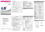
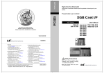
DATA SHEET LS Programmable Logic Controller XGB Compact Economy Type If you violate instructions, it can cause death, fatal injury or a Warning considerable loss of property XGB XBC-DR10E XBC-DR14E XBC-DR20E XBC-DR30E 2. Performance Specifications Safety Precautions ► Safety Precautions is for using the product safely and correctly in order to prevent the accidents and danger, so please go by them. ► The precautions explained here only apply to this module. For safety precautions on the PLC system, refer to User’s manual. ► The precautions are divided into 2 sections, ‘Warning’ and ‘Caution’. Each of the meanings is represented as follows. Caution If you violate instructions, it can cause a slight injury or a slight loss of products ► The symbols which are indicated in the PLC and User’s Manual mean as follows. This symbol means paying attention because of danger of injury, fire, or malfunction ► This symbol means paying attention because of danger of electric shock. Store this datasheet in a safe place so that you can take it out and read it whenever necessary. Always forward it to the end user Related Manual Read this data sheet carefully prior to any operation, mounting, installation or start-up of the product. Name Code XG5000 User’s Manual(Programming software) 10310000512 XGK/XGB Instruction & Programming User’s manual 10310000510 XGB Cnet I/F User’s Manual 10310000816 XGB Standard/Economic Hardware User’s manual 10310001091 ► Don’t drop or make impact. ► Don’t detach PCB from case. It may cause problem. ► When wiring, let no foreign material go into the module. If it goes into the module, remove it. ► Don’t detach the module from slot while power is on 2 4 Warning ► Protect the product from being gone into by foreign metallic matter. Risk of fire, electric shock and malfunction. Vibration resistance 5 ► Risk of fire, electric shock and malfunction. Risk of injury and fire by explosion and ignition. Shocks resistance LSIS Beijing Office _ Beijing, China Tel: 86-10-5825-6027(666) Fax: 86-10-5825-6028 . e-mail: [email protected] e-mail: [email protected] LSIS Chengdu Office _ Chengdu, China Tel: 86-20-8328-6754 Fax: 86-20-8326-6287 e-mail: [email protected] Standard 0 ~ 55℃ - -25 ~ 70℃ - 5 ~ 95%RH, non-condensing - 5 ~ 95%RH, non-condensing - For discontinuous vibration Acceleration Amplitude Frequency times 10≤f∠57 Hz 0.075 mm 10 times in 57 ≤f≤150 Hz 9.8㎨ (1G) each For continuous vibration direction Acceleration Amplitude Frequency for 10≤f∠57 Hz 0.035 mm X, Y, Z 57≤f≤150 Hz 4.9㎨(0.5G) Max. impact acceleration : 147 ㎨ (15G) Authorized time : 11㎳ Pulse wave : Sign half-wave pulse (Each 3 times in X,Y,Z directions) Square wave AC: ±1,500V impulse noise DC: ±900V Electrostatic Voltage: 4kV (Contact discharge) discharge - Radiated electromagnetic field noise Fast transient /burst noise ► Use the PLC in an environment that meets the general specifications contained in this datasheet. Risk of electrical shock, fire, erroneous operation and deterioration of the PLC. 8 ► Be sure that external load does not exceed the rating of output module. Risk of fire and erroneous operation. 10 ► Do not use the PLC in the environment of direct vibration Risk of electrical shock, fire and erroneous operation. e-mail: [email protected] LSIS Guangzhou Office _ Guangzhou, China Tel: 86-20-8328-6754 Fax: 86-20-8326-6287 Noise resistance 7 ► Tighten the screw of terminal block with the specified torque range. If the terminal screw is loose, it can cause fire and electric shock. e-mail: [email protected] Specification 9 11 Ambient conditions Operating height Pollution degree Cooling type Power supply module Voltage 2 kV Digital/analog input/output communication interface 1 kV LSIS Europe B.V., Netherlands Tel: +31 (0)20 654 1420 Fax: +31(0)20 654 1429 e-mail: [email protected] U Z No. of programs Initialization Fixed cycle External point Internal device Operating mode Self-diagnosis Program port Data keeping method at power failure Tack IEC61131-2 IEC61131-2 LSIS standard IEC61131-2 IEC61000-4-4 No corrosive gas or dust - 2000m or less - 2 or less - Natural air cooling - 18 (main +1 option) 28 38 (main+2 options) (main+2 options) P0000 ~ P127F (2,048 points) M0000 ~ M255F (4,096 points) K00000 ~ K2559F(Special area : K2600~2559F) (40,960 points) L00000 ~ L1279F (20,480 points) F000 ~ F255F (4,096 points) 100ms, 10ms, 1ms : T000 ~ T255 (256 points) (Variable by parameter setting) C000 ~ C255 (256) S00.00 ~ S127.99 D0000 ~ D5119 (5120 words) Word U00.00 ~ U0A.31 Word (256 words, analog data refresh area) Z000~Z127 (128 words) Word Max. 128 1 Max. 8 Max. 4 Max. 8 RUN, STOP Delay of operation, abnormal memory, abnormal I/O RS-232C(Loader) Setting latch area at basic parameter Dedicated protocol Modbus protocol User defined protocol Selects one port between RS-232C 1 port and RS-485 1 port by parameter Performa- 1-phase : 4㎑ 4 channels nce 2-phase : 2㎑ 2 channels 4 counter modes are supported based on input pulse and INC/DEC method Counter mode Function 1 pulse operation Mode : INC/DEC count by program 1 pulse operation Mode : INC/DEC count by phase B pulse input 2 pulse operation Mode : INC/DEC count by input pulse 2 pulse operation Mode : INC/DEC count by difference of phase Internal/External preset function Latch counter function Comparison output function Revolution number per unit time function Pulse catch 50㎲ 4 points (P0000 ~ P0003) External point 4 points: 50㎲ (P0000 ~ P0003) interrupt Selects among 1,3,5,10,20,70,100㎳ Input filter (For each module) Current consumption 250 315 355 (mA) ► Do not disassemble, repair or modify the PLC. Risk of electrical shock, fire and erroneous operation Ref. Cnet I/F function IEC61131-2 IEC 000-4-2 ► When disposing of PLC and battery, treat it as industrial waste. Risk of poisonous pollution or explosion. LSIS Qingdao Office _ Qingdao, China Tel: 86-532-8501-6068 Fax: 86-532-8501-6057 e-mail: [email protected] T C S D IEC61131-2 IEC61000-4-3 80 ~ 1,000 MHz, 10 V/m Segment Data area Built-in Function LSIS Shanghai Office _ Shanghai, China Tel: 86-21-5237-9977(609) Fax: 89-21-5237-7189 Caution ► Be sure to check the rated voltage and terminal arrangement for the module before wiring work. Risk of electric shock, fire and malfunction. e-mail: [email protected] K High Speed Counter LSIS Tokyo Office _ Tokyo, Japan Tel: 81-3-3582-9128 Fax: 81-3-3582-2667 Item Operating humidity Storage humidity 6 LSIS(ME) FZE _ Dubai, U.A.E. Tel: 971-4-886-5360 Fax: 971-4-886-5361 P M L F Operating temperature Storage temperature 1 I/O control method Specification XBCXBCXBCXBCDR10E DR14E DR20E DR30E Reiterative operation, fixed cycle operation Interrupt operation, constant period scan Scan synchronous batch processing (refresh method) Direct method by instruction Ladder Diagram Instruction List 28 677 Basic No. of instruction Application Operation speed 0.24㎲/Step (Basic instruction) Program memory 4ksteps 14 I/O points (main +1 option) First Edition Error in performance specifications is fixed KOREAN/ENGLISH data sheet integrated CI Changed V3.0 ► Do not contact the terminals while the power is applied. Risk of electric shock and malfunction. HEAD OFFICE LS Tower, 127, LS-ro, Dongan-gu, Anyang-si,Gyeonggi-do, 431-848, Korea Tel: 82-2-2034-4870 Fax: (82-2)2034-4648 e-mail: [email protected] Updated Information Applicable version For system configuration, the following version is necessary. Item Applicable version XG5000 V3.4 or above 3 - When using LSIS equipment, thoroughly read this datasheet and associated manuals introduced in this datasheet. Also pay careful attention to safety and handle the module properly. - Store this datasheet in a safe place so that you can take it out and read it whenever necessary. Version V1.0 V1.1 2011.5 No Operation method Program language Revision History Date 2010.2 2010.3 1. General Specifications Handling Precautions Item Weight(g) 330 340 450 485 465 Precautions for use ► Do not Install other places except PLC controlled place. ► Make sure that the FG terminal is grounded with class 3 grounding which is dedicated to the PLC. Otherwise, it can cause disorder or malfunction of PLC PLC Others PLC Others PLC Others Homepage: http://eng.lsis.biz A) Best LS constantly endeavors to improve our products so that information in this datasheet is subject to change without notice. The date of issue: 2011. 5 10310001095 Ver 3.0 3. Parts Name and Descriptions ► ► ► ► ► C) Bad B) Good Connect expansion connector correctly when expansion module is needed. Do not detach PCB from the case of the module and do not modify the module. Turn off power when attaching or detaching module. Cellular phone or walkie-talkie should be farther than 30cm from the PLC. Input signal and communication line should be farther than 10cm from a hightension and a power line in order not to be affected by noise and magnetic field. 5. Built-in High Speed Counter Function (1) Summary The high-speed counter can count high frequency pulse which can not be processed with the input unit. It can count pulse which occurs from encoder or pulse generator. (2) Performance Specification Item Specification Signal A Phase, B Phase Signal Input DC24V level Signal Signal Voltage Input (Open collector) Type Counting range Signed 32 Bit (-2,147,483,648 ~ 2,147,483,647) Counting speed 1-phase: 4kpps 4 channels 2-phase: 2kpps 2 channels Counter format Linear counter / Ring counter 1 pulse operation Mode : INC/DEC count by program 1 pulse operation Mode : INC/DEC count by phase B pulse input Counter mode 2 pulse operation Mode : INC/DEC count by input pulse 2 pulse operation Mode : INC/DEC count by difference of phase (4 multiplication) Internal/External preset function / Latch counter function Function Compare output function / no. of rotation per unit time (2) Input Filter Function The input filter function can be used to reject noises. The input filter constant from the range of 1-100㎳ can be designated. (1) XBC-DR10/14E (a) Usage Input signal status affects the credibility of system where noise occurs frequently or pulse width of input signal affects as a crucial factor. In this case the user sets up the proper input on/off delay time, the trouble by miss operation of input signal may be prevented because the signal which is shorter than set up value is not adopted. (b) Operation Explanation Input filter constant (Filter time) Input signal Input image data Time Input signal 6. PID Control Function No ① ② ③ ④ ⑤ ⑥ ⑦ ⑧ ⑨ ⑩ ⑪ Name Input status LED Description ■ Indicates input status. ■ Connector to connect with XG5000 PADT Connector •RS-232C 1 channel Input terminal block ■ Input Terminal Block Output terminal block ■ Output terminal block ■ Sets the operation mode of main unit. • STOP → RUN : Operation execution of RUN/STOP mode program switch • RUN → STOP : Operation stop of program (In case of STOP, it can be changed to remote mode) Output status LED ■ Indicates output status ■ Indicates the operation status of the main unit • PWR(RED ON) : Indicates power status. Operation status LED • RUN(GREEN ON) : RUN mode • ERR(RED blink) : indicates error Built-in ■ Terminal block for built-in RS-232C/485 Communication communication Terminal block Power terminal block ■ Terminal block for power (AC 100~240V) ■ Dip switch for selecting Operation or O/S download mode O/S mode dip switch •On: BOOT mode. Downloading O/S is available •Off: User mode. Downloading program by PADT is available Option board holder ■ For connecting option board (1) Dedicated communication XGB Compact Type has built-in Cnet communication function, and can communicate with various external devices without expansion Cnet I/F module. (XGB Compact Type Main Unit has built-in RS-232C and RS-485.) Built-in Cnet of XGB Main Unit supports the following functions; (a) Read single/continuous device (b) Write single/continuous device (c) Register monitoring device (d) Execute monitoring (e) 1:1 connection system (LS link) (a) Usage (2) User defined communication User can define a user-defined protocol to communicate with other manufacturer’s devices. By supporting user-defined protocol, XGB PLC can communicate with various devices which have their own protocol. (3) Modbus protocol XGB PLC includes Modbus protocol, and it is easy to connect to Modbus devices. (It is not necessary to write Modbus protocol as user-defined protocol.) (4) P2P communication support XGB PLC supports client function service with P2P form to above item. Remarks 1) Please refer to XGB Cnet I/F User’s Manual for the details of built-in Cnet I/F function. 7. Other Built-in Function (1) Pulse Catch Function In the main unit, 4 pulse catch input contact points (P000~P003) are included. Through using this contact point short pulse signal (min. 50㎲) which cannot be executed by general digital input can be taken. (a) Usage When narrow pulse signal is input which can not be executed by general digital input, the operation can not performed as user's intention. But in this case through pulse catch function even narrow pulse signal (min. 10㎲) can be executed. (b) Operation Explanation Option module #1~2 Input signal Mounting module Input image data scan1 Step Scan1 Scan2 Scan3 scan2 Narrower width pulse than input filter constant is not considered as input signal. (3) External interrupts function XGB PLC can perform max 4 external contact tasks by using input of main unit without special interrupt module (1) I/O No. Allocation grants address to unit & module for input/output data No. of module can Ref. be mounted 1 10/14 points unit Option module 2 20/30 points unit (2) The following is method of I/O number allocation Area Item Ref. Input Output Main unit P0000 ~ P003F P0040 ~ P007F Fixed Option #1 P0400~P043F 64point fixed Option #2 P0440~P047F 64point fixed -. I/O allocation for all expansion modules is fixed at 64points (The unused area can be used as internal relay) (2) XBC-DR20/30E Input image data 4. I/O No. Allocation Method Main unit 8. Dimension (㎜) scan3 Execution contents CPU senses input when pulse signal of min. 50㎲ is input, then saves the status. Turns on the region of input image. Turns off the region of input image This function is useful when you need to process operation related to external input signal fast without scan time. (b) Operation Explanation 9. Warranty External input signal Scan program In case of occurrence of external interrupt signal pauses being executed scan program and processes interrupt program Scan program Interrupt Program Ends the interrupt program process then resumes to execute scan program. (c) Function 1) It can be use the max. 4 point input (P000 ~ P003). 2) Input 4 points (P000 ~ P003) of XGB Compact Type Main Unit are shared for several functions as following table. 3) Each of the functions can be disabled according to whether other functions are enabled. High Speed External Input Point Pulse Catch Input Filter Counter Interrupt P000 Ch0 Input Unavailable Unavailable Available P001 Ch1 Input Unavailable Unavailable Available P002 Ch2 Input Unavailable Unavailable Available P003 Ch3 Input Unavailable Unavailable Available (1) Warranty period LSIS provides an 18-month-warranty from the date of the production. (2) Warranty conditions For troubles within the warranty period, LSIS will replace the entire PLC or repair the troubled parts free of charge except the following cases. (a) The troubles caused by improper condition, environment or treatment except the instructions of LSIS. (b) The troubles caused by external devices. (c) The troubles caused by remodeling or repairing based on the user’s own discretion. (d) The troubles caused by improper usage of the product. (e) The troubles caused by the reason which exceeded the expectation from science and technology level when LSIS manufactured the product. (f) The troubles caused by natural disaster. (3) This warranty is limited to the PLC itself only. It is not valid for the whole system which the PLC is attached to.