1
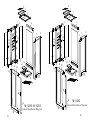
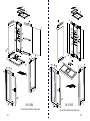
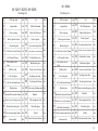
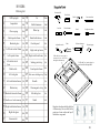
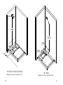
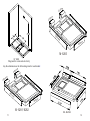
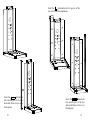
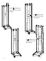
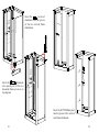
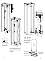
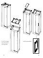
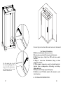
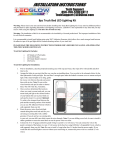
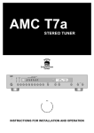
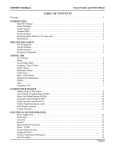
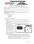
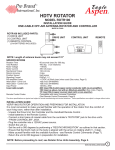
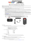
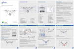
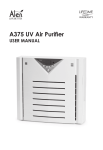
INSTALLATION MANUAL OF STEAM ROOM 1 2 2 3 3 22 22 4 5 21 20 6 19 23 24 20 23 24 18 17 28 17 25 16 27 8 7 6 19 18 25 5 21 8 7 4 15 13 14 16 27 29 28 15 14 13 29 26 26 12 10 12 11 10 11 9 9 30 30 31 31 34 01 33 M-8283/ M- 8283 General Installation Diagram M-8282 General Installation Diagram 34 33 32 02 22 M-8284 General Installation Diagram 03 M-8285 General Installation Diagram 04 M- 8282 M- 8281/ 8283/ M- 8285 Packing List Packing List 1 LED top light 1set 18 2 Lampshade 1set 19 3 Glass coping 1set 20 10set 1 LED top light 1set 18 Shelf aluminum 2set 2 Lampshade 1set 19 Shelf aluminum 2set Hand-hold shower 1set 3 Glass coping 1set 20 Hand-hold shower 1set Jet Jet 10set 4 Back topside frame 1pc 21 Control panel 1set 4 Back topside frame 1pc 21 Control panel 1set 5 Backside glass 1pc 22 Up connecting frame 2pc 5 Backside glass 1pc 22 Up connecting frame 2pc switch valves for functions 1pc 6 6 7 8 Left front vertical frame 1pc 23 Left topside frame Left side back vertical frame 1pc 24 Cold and hot water 1pc 7 1pc 25 Backboard glass 1pc 8 Left front vertical frame 1pc 23 switch valves for functions 1pc Left topside frame Left side back vertical frame 1pc 24 Cold and hot water 1pc 1pc 25 Backboard glass 1pc 9 Marble slab 2pc 26 Front vertical frame 2pc 9 Marble slab 2pc 26 Front vertical frame 1pc 10 Left side glass 1pc 27 Sealing joint strip 16pc 10 Left side glass 1pc 27 Sealing joint strip 16pc 11 Left side bottom frame 1pc 28 Front topside frame 1pc 11 Front topside frame 1pc 12 Bottom tray 1pc 29 Side water-holding strip 2pc 12 1pc 30 1pc 13 Backside downside frame Small cover for bottom tray 1pc 31 Glue magnetic strip 1pc 14 1pc 32 Movable glass 1pc 15 16 Down connecting frame 2pc 33 Gemel 2pc 17 8pc 34 Front downside frame 1pc 13 Backside downside frame 14 15 Backside board glass Steam outlet Handle Left side bottom frame 1pc 28 1pc 29 Side water-holding strip 2pc 1pc 30 1pc Small cover for bottom tray 1pc 31 Glue magnetic strip 1pc 1pc 32 Movable glass 1pc 16 Down connecting frame 2pc 33 Pulley 4pc 17 8pc 34 Front downside frame Bottom tray Backside board glass Steam outlet Handle 1pc 06 : M-8284 Packing List Percussion drill Wood block 1 LED top light 1set 18 2 Lampshade 1set 19 Shelf aluminum 2set 3 Glass coping 1set 20 Water tap 1set Hand-hold shower 1set 4 Back topside frame 1pc 21 5 Backside glass 1pc 22 6 7 8 Left front vertical frame 1pc 23 Left topside frame Left side back vertical frame 1pc 25 Sealing joint strip 1pc Front topside frame 2pc 26 10 Left side glass 1pc 27 11 Left side bottom frame 1pc 28 12 Bottom tray 1pc 29 1pc 30 Small cover for bottom tray 1pc 31 15 Right side bottom frame 1pc 32 16 2pc 33 8pc 34 17 Steam outlet Level feet Adjustable wrench Drill bit( Plastic hammer Pliers 、 ) Cross screwdriver Straight screwdriver Pencil Silicon sealant gun Measuring tape Right side top frame 1pc 1pc 2pc Right side glass 2pc 24 Right side front frame Marble slab 14 Control panel 10set 1pc 9 13 Backside downside frame Jet Cold and hot water pipe is connected into this hole through the bottom tray Cold and hot water pipe is pre-buried in this position Side water-holding strip 16pc Handle Glue magnetic strip Movable glass Gemel 1pc 2pc 1pc 1set Regulate the adjustable foot holder of bottom tray, to low a little bit the position of water outlet and lay all the holders on ground. 08 Power I np ut Pre w - bu rp ate r ie dp ipe o si tio o eam f st nf or co l m roo da nd hot w ate rp ipe M-8281/M-8282/M-8283 Diagram for water and electricity 09 M-8284 Diagram for water and electricity 10 213 213 mm mm 10 10 36 36 mm mm 640 mm M-8283 M - 8285 Diagram for water and electricity Lay the aluminums as the below diagrams for each model 240 240 mm mm 88 88 6m 6m m m 790 mm M- 8281/8282 M- 8284 11 12 Insert the alu into the backboard alu as to the below diagram M-8285 Insert the two pieces front and back screws of downside frame alu into the groove of backboard alu. 13 Insert two glasses into the groove of backboard alu and bottom frame 236* 2044 Installation Steps (Take M-8281 as an example for other models) 14 Insert the aluminum into the groove of the two vertical frame aluminums. Insert the aluminum into outside part of the two downside frame screws as to the diagram 15 Insert the aluminum into outside part of the two downside frame screws as to the diagram 16 Insert the aluminum into the groove of the two vertical frame aluminums. Put aluminum into the groove of the two vertical frame aluminums. Put aluminum into the groove of the two vertical frame aluminums. 17 18 1062 * 204 Insert the screws of aluminum into the groove of the two vertical frame aluminums. Insert the glass into the groove of backboard aluminum 4 Insert the aluminum into outside part of the two downside frame screws as to the diagram Insert the 664*2044mm glass into the groove of the vertical side frame aluminum. 19 20 Insert the screws of aluminum into the groove of the two vertical frame aluminums. 640 465* 2 044 mm Insert the aluminum into outside part of the two downside frame screws as to the diagram Insert the 465*2044mm glass into the groove of the vertical side frame aluminum. 21 22 Install the gemel and the fixed glass and install the parts as to the diagram Insert the screws of aluminum into the groove of the two vertical frame aluminums. Insert the sealing joint strip into the gap between glass and aluminum Sealing joint strip Aluminum end cap Door bottom waterholding aluminum Water-holding adhesive tape 23 24 Use the 4*20 self tapping screws to fix the top cover onto the topside frame. 25 Install the top lamp and handle 26 Connect the power and use this steam room as to the manual. Use the sealing glue to seal the connecting alu gaps at the inner side of the steam room, and do not use the steam room till 24hours later. User Manual of Steam Room ◆Multicolor and dynamic fluorescent screen. ◆System turn on auto infall; System turn off auto drain ◆ With Steam, Spray, Light, Fan, MP3 and other control functions ◆ Range of steam time: 10~60minutes; Range of steam temperature:0~90ºC ◆ With automatic temperature control and multi-protective function from over-temperature, dry-heating, over-voltage, leakage and so on ◆Side spray function(top spray, bottom spray) ◆ Built-in stereo FM Radio module with automatic search station function 27 INSTALLATION INSTRUCTION: 28 ◆ NOTICE: Only after strictly checking water intake pipes, steam pipes and connecting lines of the power control cabinet and confirming pipeline unblocked and wires in order can the product be switched on and work (Note : Never open the steamer in shortage of water). The main engine of the steamer and power control cabinet should NOT be installed in the shower room. The main engine must be installed in the vertical direction showed by the arrow on the machine body. Inner hole of steam pipeline should be over 15mm. Installation of valves on the exhausting steam pipes is strictly forbidden. Electrical equipment not recommended by the manufacturers should NOT be connected to the machine. Unauthorized disassembling and repacking the already fixed wirings in the machine or pulling up and insert the wirings and plug-ins in the power control cabinet is strictly prohibited. Pipelines should be connected to the water outlet of the main steam engine in during installation in order to leading water to the drainage location of the room body. It is suggested that water purifier be connected to the inlet of the product so as to prolong the usage life of the machine. In hard water area, the main steam engine should be cleaned and water scale eliminated regularly. It is suggested that the main steam engine be checked every three months and cleaned according to the scaling situation. The procedures are as follows: dilute 5-10 grams of citric acid with 1.4 liter warm water, dismantle the pipe connecting to the outlet of the main engine, inject the citric acid solution from the outlet, connect the steam pipe, leave it aside for 60 minutes, switch on the machines and heat 30 minutes, switch off the machine and empty it. Connecting wirings of the power control cabinet should be connected according to the plug-in parameters and specifications, and output wirings should not be mutually short circuit.. The machine should be installed in strict accordance with the installation regulations by qualified personnel. Note: The Company shall claim no responsibility when users violate the provisions of the instruction and result in adverse consequences. Operation Instructions:controlle keyboard function as follows. Fan Power switch Time setting Radio/MP3 switch Volume/FM switch MEM Lighting Lighting Steam Temperature setting - Key parameter + Key parameter 29 Diagram One: controlle keyboard function as follows. System turn on: Press random button can start the machine when electricity is on. The LCD indicates current screen room temperature, lights are on and the system is in stand-by status. Steam:Press the Steam button can turn on/off the light and LCD showsON/OFF- of Steam and its working status. Temperature setting: Press Temperature+、 - button to set steam temperature, each press on Temperature+、- button once can Increase or reduce 1℃ .(pre-set default value is 40℃ ). When environmental temperature is higher than the pre-set temperature, steam can not be turn on. Time setting: Press Time+、 - button to set the steam time, each press time+、- button once can increase or reduce 1min((pre-set default value is 20min) ◆ Spray: Press the spray key for the first time, the top spray will work and the LCD shows Top Spray signal; Press the spray key for the second time, the bottom spray will work and the LCD shows Bottom Spray signal; Press the spray key for the third time, the cycle spray function will be activated, and change the direction from top to bottom every five seconds; Press the spray key for the fourth time, all the spray function and the LCD stops. ◆ Lighting: Press the Light button to turn on/off the light and LCD showsON/OFF- of light and its working status. 30 ◆ Fan: Press the Fan button to turn on/off the light and LCD showsON/OFF- of Fan and its working status. ◆ Radio/MP3 switch: Press the Radio/MP3 switch key for the first time to turn on the Radio function, and the LCD will show the Radio working signal; Press the Radio/MP3 switch key for the second time to turn off the Radio function and to turn on the MP3 function, and the LCD will show the MP3 working signal; Press the Radio/MP3 switch key for the third time, the system will turn off the Radio/MP3 function and the LCD will lose all the signals. The system is embedded with stereo FM radio with frequency display, digital tuning and automatic searching and stored function. Under the working status of Radio function, press the MEM for two seconds, the system will search the channels between 88.0MHz~108.0MHz, and store up the wellreceived channels at one time under better signal. If the stored channels are not well received, press MEM key to delete the channels. If need searching by manual, press the VOLUME/FM switch key to enter the searching status, and press the + or key to adjust the channel between 88.0MHz~108.0MHz; If pressing the + or key without stop, the system could search the channels automatically between 88.0MHz~108.0MHz, when the channel is found, the system will stop searching and start to play this channel, then press MEM key to store this channel. Under the working status of MP3 function, press the Volume/FM switch key , and press the + or key to choose the list on the MP3 ■ Volume setting: Press the Volume/FM switch key to enter the Volume adjusting status, and press the + or key to adjust the volume. ◆ add Aroma/ liquid medicine: drop the aroma/ liquid medicine into the screw hole at the top of the steam output on the steam machine, and start to use it. ◆ System switch off: Press the power on/off key, to shut down all the function and screen content.