1
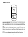
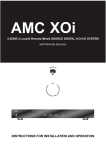
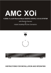
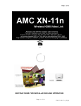
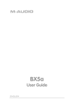
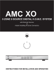
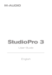
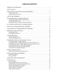
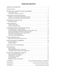
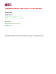
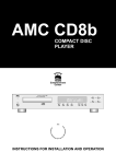
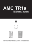
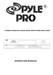
AMC T7a
STEREO TUNER
AMCTM
HOME
Entertainment
Center
INSTRUCTIONS FOR INSTALLATION AND OPERATION
RISK OF ELECTRIC SHOCK
DO NOT OPEN
RISQUE DE CHOC ELECTRIQUE
N OUVRIR PAS
RIE SGO DE ELECTROCHOQUE
NO ABRIR LA TAPA
CAUTION: TO REDUCE
THE RISK OF ELECTRIC
SHOCK, DO NOT REMOVE
COVER (OR BACK).
NO USER-SERVICEABLE
PARTS INSIDE. REFER
SERVICING TO QUALIFIED
AFIN DEVITER UN
CHOC ELECTRIQUE
ET LES CONSEQUENCES
GRAVES QUI POURRAIENT
EN RESULTER, TENTEZ
PAS D'OUVRIR L'APPAREIL
ET DE TOUCHER AUX
COMPOSANTS INTERNES
SANS LA PRESENCE D'UNE
PARA REDUCIR EL RIESGO
DE SACUDIDAS ELECTRICAS,
NO DEBERA QUITARSE LA
TAPA (NI PARTE POSTERIOR).
CONSULTESE AL PERSONAL
CAPACITADO PARA LAS
WARNING: TO PREVENT FIRE OR ELECTRIC SHOCK, DO NOT EXPOSE THIS APPLIANCE TO RAIN OR
MOISTURE.
ADVERTENICIA: PARA EVITAR EL RIESGO DE INCENDIO O SACUDIDA ELECTRICA, NO DEBERA
CAUTION: TO PREVENT ELECTRIC SHOCK DO NOT USE THIS (POLARISED) PLUG WITH AN
EXTENSION CORD, RECEPTACLE OR OTHER OUTLET UNLESS THE BLADES CAN BE FULLY INSERTED
TO PREVENT BLADE EXPOSURE.
ATTENTION: POUR PREVENIR LES CHOCS ELECTRIQUES NE PAS UTILISER CETTE FICHE POLARISEE
AVEC UN PROLONGATEUR. UNE PRISE DE COURANT OU UNE AUTRE SORTIE DE COURANT, SAUF
SILES LAMES PEUVENT ETRE INSEREES A FOND SANS EN LAISSER AUCuNE PARTIE FOND SANS EN
LAISSER AUCUNE PARTIE A DECOUVERT.
PRECAUCION: PARA EVITAR SACUDIDAS ELECTRICAS, NO DEBERA UTILIZARSE ESTA CLAVIJA
POLARIZADA CON UN CORDON DE PROLONGACION, RECEPTACULO U OTRO TIPO DE SALIDA A
MENOS QUE SE HAYAN INSERTASO COMPLETAMENTE LAS LENGšETAS PARA EVITAR SU
NOTE: Some AMC products are equipped with dual or multi-voltage transformers (which is indicated on the
back panel). If you wish to change the voltage, please bring your unit to an authorised AMC service technician
for internal conversion.
ATTENTION: Quelques pi ces AMC sont munies de transformateurs double ou multi-voltage (indiqu au
panneau arri re). Si vous voulez changer le voltage, veuillez apporter votre appareil au fournisseur de AMC
pour le transformer.
ZUR BEACHTUNG: Einige AMC Ger te sind mit Umschaltern f r unterschiedliche Netzspannungern
ausger stet (Ein Vermerk auf der R ckseiteweistdarauf hin).
Die Anpassung, wenn notwendig, mu von einem qualifizieren Techniker in einer AMC Servicestation
vorgenommenwerden.
NOTA: Ciertos componentes de AMC est n dotados de transformadores de doble tensi n o de varias
tensiones (Io que se indica en el panel posterior). Si se desea cambiar la tensi n, s rvanse llevar el aparato a
NOTE TO CATV systems installer: This reminder is provided to call the CATV system installer's attention to
Article 820-22 of the NEC that provides guidelines for proper grounding and, in particular, specifies that the cable
ground shall be connected to the grounding system of the building, as close to the point of cable entry as practical.
NOTA PARA EL INSTALADOR DE ANTENAS DE TELEVISION COLECTIVAS: La presente advertencia se
provee para llamar la atenci n del instalador al Art culo 820-22 de NEC (C rdigo El ctrico Nacional) donde se
facilitan las directrices para la pertinente puesta a tierra y que especifica en particular que el condutor a tierra del
cable debe connectarse al sistema de conexi n a tierra del edificio, lo m s proximo posible al punto de entrada
The lightning flash with arrowhead, within an equilateral
triangle, is intended to alert the user of the presence
of uninsulated" dangerous voltage" within the
product's enclosure; that may be of sufficient
magnitude to constitute a risk of electric shock
to persons.
The exclamation point within an equilateral triangle is
intended to alert the user of the presence of
important operating and maintenance (servicing)
instructions in the literature accompanying the
appliance.
APPLICATION AND FEATURE LIST
Features of the AMCmodelT7a
* The AMC model T7a was designed to meet professional quality standards for receiving
FM or AM programs.
* Components of the highest grade are used throughout with critical ones selected for the
best sound performance, such as double-sided and thru-hole plated PCB for the best
stability from RF through IF to audio.
* It is simple and easy to use, and offer a superb audiophile quality performance at a very
reasonable price.
* 30 stations (FM or AM) can be entered in the preset mode. They are stored in a non
volatile memory which allows the preset stations to remain in memory for more than two
weeks even if the unit is unplugged from the mains supply.
* In case of weak stations where the background noise becomes annoying and spoils the
listener's enjoyment of the program, there provides a MONO button on T7a to lock the
tuner in themonomodetoobtainconsistently quieter and cleaner sound.
* Its simple circuit topology gives the unit noise free and low distortion performance.
* Provides two options to upgrade the unit:
(1) RDS module: To offer the convenience and benefits of RDS (Radio Data System) but
without superfluous and confusing buttons.
(2) Digital output module: To have digital output from tuner in order to be able to make
digital recording through AMC ADC with digital pre-amp structure.
2
REAR PANEL CONNECTIONS/FRONT PANEL CONTROLS
REAR PANEL
2
3
5
4
1
4. OUTPUT JACKS
5. DIGITAL OUTPUT "(OPTION)"
1. AC LINE CORD
2. FM ANTENNA TERMINAL
3. AM ANTENNA TERMINAL
FRONT PANEL
8 9
1
10 11
2
3
1. POWER SWITCH AND POWER
INDICATOR
2. STATION PRESET
3. MEMORY
4. AM/FM
5. MONO
4
5
6. AUTO
7. TUNING
8. TEXT
9. TIME
10. PROGRAM
11. TYPE
3
6
7
REAR PANEL CONNECTIONS
station you can rotate the antenna for best
reception.
(2) A more elaborate rabbit-ears indoor TV
antenna with a tuning switch. This type of
antenna does NOT have greater sensitivity
than the simpler rabbit-ears unit, so if your
problem is that the signals you want to
receive are weak, then an outdoor antenna
is the only effective solution. But in cities
and in large buildings where signals are
strong but are contaminated by reflected
"multipath" signals that interfere with good
reception, the tuning switch on an
elaborate indoor antenna may improve
reception by reducing the interference.
(3) An electrically tuned indoor antenna.
Again, such antennas usually do not
provide any advantage over the simplest
type of "rabbit-ears" unit for receiving weak
signals. But where strong signals are
contaminated with interference, the
antenna's aiming and tuning controls can
reject the interference and yield cleaner
reception.
(4) An outdoor antenna. Even the finest
indoor antenna, no matter how elaborate,
cannot fully exploit the capabilities of a
good FM tuner. For the lowest noise,
minimum distortion, and largest choice of
wellreceived broadcasts, an outdoor
antenna is the best complement to a fine
tuner. A roofmounted antenna has three
fundamental advantages. First, its large
size yields better sensitivity (pulling in a
stronger signal form the desired station)
and a narrower directional pattern for more
effective rejection of multipath reflections
arriving form other directions. Second, its
location on a roof or tall mast places it
above many sources of interference such
as passing cars and buses, other buildings,
etc. Third, the strength of received FM
signals is directly proportional to the height
of any antenna above the ground. If you
already have an outdoor television
antenna, using a splitter to extract FM
signals from it may produce excellent
results. However, many TV antennas are
1. AC LINE CORD
Plug the AC line cord into a nearby wall
outlet that provides the correct AC power
line voltage, or into an unswitched
convenience outlet on any AMC product.
2. FM ANTENNA TERMINAL
An antenna must be connected to the tuner
for effective receipt of stereo FM
broadcasts. A ribbon-wire "folded dipole"
antenna is included to get you started.
When you stretch out the ribbon-wire
antenna you will note that it is the form of a
T. The "crossbar" portion of the T should
be stretched out horizontally and tacked in
place on a wall, on the back of a cabinet, or
on the floor. The "vertical" section of the T
goes to the 75 ohm FM antenna terminal
through 300 ohm to 75 ohm matching
transformer included in accessory
package.
In view of the exceptional sensitivity of
AMC tuner circuits, you may find the
ribbon-wire dipole antenna is all you need
for receipt of strong local stations. But it is
not very efficient at rejecting "multipath"
and other forms of FM interference, and it
cannot be easily rotated to optimize its
pickup pattern for best reception of stations
in different directions. The recommended
options, in order of increasing cost, are as
follows:
(1) A basic "rabbit-ears" indoor TV antenna
without auxiliary coils or tuning switches.
Electrically, such an antenna is just another
dipole (similar to the ribbon-wire antenna)
with its tuned elements made of solid
metal, but with the advantage of being able
to be rotated. Stretch out each of its two
arms to a length of 30 inches (75cm), and
orient them horizontally or at a shallow
angle less than 45 degrees upward. The
ribbon wire emerging from the antenna's
base should be connected to the tuner's 75
ohm FM antenna terminal through 300 ohm
75 ohm matching transformer in place of
the supplied ribbon-wire antenna. Now, for
each station in tune, after you tune the
4
effectiveness of a longwire antenna will be
improved by connecting a second wire
from the Ground (G) terminal to a true
earthground, i.e. a copperplated rod driven
several feet into earth.
A substitute
electrical ground may also improve
effectiveness: a coldwater pipe, a seam
radiator, or the third hole of modern
electrical wall socket.
potential interference with TV signals at
nearby frequencies (channel 6 in the U.S.).
You may be able to use a splitter to extract
FM signals from an apartment building's
master TV antenna system, but usually this
yields poor results because many master
antenna systems have "traps" to stop FM
signals. The best choice is a directional
FM-only antenna, mounted as high above
ground as is practical and separated by at
least two meters (7 feet) from other
antennas, vertically and horizontally. If
desired stations are located in different
directions (more than 90 degrees apart),
the antenna should be mounted on a rotor
for aiming. Use shielded leading cable
rather than plain "twinlead" wire, both to
minimize interference and to preserve
strong signals during years of weathering.
The cable may be either 75ohm coaxial or
shielded 300ohm type. Disconnect any
indoor antenna before connecting the
cable form the outdoor antenna. If you
install an outdoor antenna yourself,
observe these important CAUTIONS:
a. Do not mount the antenna close to
electric power lines. Plan the installation
so that the antenna mast cannot
accidentally touch power lines, either while
you are installing it or later.
b. Include a lightning arrester in the
installation, to protect both yourself and the
tuner circuit from potential danger during
electrical storms.
4. OUTPUT JACKS
Connect a stereo patch cord from the Left
and Right output jacks to the
corresponding Tuner input jacks on your
amplifier.
5. DIGITAL OUTPUTS (OPTION)
This is an option model for T7a. If your
AMC T7a has incorporated with Digital
Output Module the unit will be available
with digital output in two types of jacks
(RCA Jack and Toslink Jack). For details
please check with AMC dealer/distributor
in your country.
3. AM ANTENNA TERMINALS
Since the tuner is equipped with loop
antenna, no external antenna will be
needed for satisfactory reception of most
local broadcasting stations. But if you wish
to improve reception of distant AM stations,
attach a longwire outdoor antenna to the
AM terminal. As its name implies, a
"longwire" antenna is a simple, straight
wire whose length may be anything from a
few feet up to about 100 feet (30 meters),
mounted parallel to the earth and as high
as convenient.
In some cases the
5
FRONT PANEL CONTROLS
other stations that you want to store in the
remaining presets. Incidentally, if you make a
mistake or change your mind, it is not
necessary to reprogram all presets in
sequence. You can reprogram any preset
simply by tuning to the desired frequency,
press MEMORY, and pressing the preset #
that you want to reprogram. After you finish
programming the presets, you may wish to
post your list of stations and associated preset
numbers nearby for reference. CAUTION: in
day-to-day operation be careful not to press
the MEMORY button by accident. Doing so
will activate the MEMORY mode, and if you
then press any of the preset buttons you will
unintentionally reprogram that preset. You
would then have to manually retune to the
station you wanted, and reprogram it into the
preset. If you press MEMORY accidentally,
you may wait ten seconds for the MEMORY
mode to disengage. Or you can immediately
force the tuner out of the MEMORY mode, in
either of two ways: switch to the other tuning
band (e. g. from FM to AM and back), or tap
tuning buttons to change the tuned frequency.
1. POWER SWITCH
The AMC T7a is turned on by pressing the
power switch. The small indicator above the
switch will glow green.
2. STATION PRESETS
You can store the frequencies of thirty favorite
stations (FM and AM), in these presets, using
the MEMORY button. Then, to tune those
stations from day to day, just press the
appropriate presets buttons. The presets
preserve their frequency assignments when
the power is switched off, or when the AC line
cord is unplugged, for a period of at least two
weeks. Thus you can rearrange your stereo
system, or move the equipment from room to
room, without losing the preset frequencies.
But if you leave the power off for a month or
more, you may have to reprogram the tuning
presets.
3. MEMORY
This button engages the Memory enter mode.
Use this mode to enter the frequencies of your
favorite stations in the thirty presets (FM and
AM). The procedure is as follows.
(1) Decide which station you want to assign to
each preset.
(2) Select the FM or AM band, as appropriate.
Using the Tuning control, manually tune to the
first station on your list. Check the centertune indicator to be sure that you have tuned
precisely to the center of the station's
broadcast channel. Press the MEMORY
button, then press Preset #01 to store the first
station in the tuner's memory. (NOTE: After
you press MEMORY, you will have
approximately five seconds to store a station
in one of the presets. After that interval, the
MEMORY mode will automatically
deactivate).
(3) Tune to the second station on your list.
Press the MEMORY button and, within ten
seconds, press Preset #02 to store the
second station.
(4) Tune to the third station on your list, press
MEMORY and press Preset #03 to store the
station. Continue in this manner with any
4. AM/FM
This button switches between the two tuning
bands: FM or AM. The digital tuning display
shows the tuned frequency in MHz (for FM) or
KHz (for AM). The tuning circuit has a "last
station selected" memory. When you switch
between tuning to bands, the circuit
automatically retunes to the last station that
you tuned to when you previously used that
band.
5. MONO
The MONO button disables the stereo FM
circuits in the tuner. Normally the tuner
receives monophonic FM transmissions in
mono and automatically switches on its
multiplex decoding circuits when a stereo FM
broadcast is received (as shown by the
STEREO indicator). But when a very weak
FM station signal is received, it may be
excessively noisy because of the multiplex
encoding technique used for stereo
6
shift up or down by this increment, as shown
on the digital frequency display. To tune a
broadcast signal, press continuously on either
TUNING button till the tuned frequency is
close to the desired broadcast frequency.
Then finetune in small increments by tapping
the Tuning buttons. If you know the exact
frequency of the broadcast station, simply
tune to that frequency. If you don't know the
exact frequency, tune to the vicinity of the
correct frequency and then observe the
Tuning indicators while finetuning to obtain
maximum signal strength. On FM, finetune till
the centertune indicator is illuminated.
order to obtain consistently quieter and
cleaner sound. Remember to disengage the
MONO button when you retune to a stronger
signal. As long as the MONO button is
engaged, no broadcasts can be received in
stereo.
6. AUTO
When the AUTO button is engaged, a red LED
on the display will be lit, otherwise the unit is in
MANUAL mode. In AUTO mode, the tuner
scans is in a station-by-station mode rather
than in small frequency increments. When
the Tuning buttons is tapped, the tuner scans
rapidly up or down in frequency and
automatically stops at the next station whose
signal is strong enough for good reception. A
muting circuit automatically silences the
output during the scan, till the tuning circuits
lock onto a station. The MANUAL tuning
mode partially overrides the scan muting. In
this mode all stations (and the interstation
noise) remain audible at a reduced volume
level while the tuning is being scanned up or
down in frequency. If you want to search for
very weak signals, or if you need to fine tune
away from the center of a station's
broadcast channel in order to cure an
interference problem, use the manual tuning
mode.
8. TEXT
When the TEXT button is pressed, a repeated
textual message will be scrolled through the
display.
If the selected station is not
transmitting a TEXT message, "NO TEXT"
will appear on the display.
9. TIME
When the TIME button is pressed, the time is
displayed. The first two characters on the left
hand side of the display will indicate either AM
or PM, followed by the time. If the selected
station is not transmitting a time signal, "NO
CLOCK" will appear on the display.
10. PROGRAM
When the PROGRAM button is pressed, the
selected station name will appear on the
display. If the selected station is not
transmitting the station name, "NO NAME"
will appear on the display.
7. TUNING
The TUNING controls are two buttons that
allow you to tune up and down the AM of FM
radio spectrum. Press the right-hand button
to tune toward higher frequencies or the
lefthand button to tune toward lower
frequencies. When the TUNING buttons are
pressed momentarily, the tuned frequency
shifts up or down by one step, unless the
AUTO mode has been engaged. (If AUTO is
engaged the tuner will scan in a station-bystation mode rather than in small tuning
steps.) In North America the size of the
minimum tuning step is 10KHz on the AM
band and 200KHz on the FM band. In Europe
and elsewhere the tuning step is 9KHz on AM
and 50KHz on FM. Each time the TUNING
buttons are tapped, the tuned frequency will
11. TYPE
When the TYPE button in pressed, the type of
program material transmitted by the selected
station will be displayed, e.g. News, Classic,
Pop, Sport etc. If the selected station is not
transmitting TYPE information, "NONE" will
appear on the display.
Notes: When your T7a is not installed with
RDS module, you will not find these RDS
functions that are described from item (8) to
(11) on your unit. For details to upgrade your
7
REMOTE CONTROL
MEMORY
1
2
3
4
5
6
7
8
9
0
AM/FM
SCAN
AM/FM
PROGRAM
TEXT
TAPE
AMC
PRESET
RC-006
A wireless remote control is provided with your T7a enabling you to operate from the comfort
of your chair. For reliable operation there should be a clear line-of-sight path from the remote
control to the front of the tuner.
Most buttons on the remote control produce the same effect as the corresponding
button on the front panel of the tuner. To understand these functions please refer to
relevant sections. However, the handset is also equipped with two functions (SCAN and
PRESET) that are not found on front panel. The operations of these functions are described
as follows:
SCAN
The SCAN has two buttons that allow you to tune up and down the AM of FM radio spectrum.
Press the ' ' button to tune toward higher frequencies or ' ' button to tune toward lower
frequencies. When the SCAN buttons are pressed momentarily (<0.5 second), the tuned
frequency shifts up or down by one step. When the SCAN buttons are pressed and held
more than 0.5 second, the tuner will scan in a station-by-station mode rather than in small
tuning steps.
PRESET
Once the frequencies of favorite stations (up to 30 in either FM or AM) have been stored in
this unit. To see how to set upmemory stations please refer toMEMORY description.
Then, just press the PRESET buttons and the stations in the memory of the unit can be easily
8
SPECIFICATIONS
FM TUNER SECTION
Input Sensitivity MONO 30 dB THD+N.......................................11.3 dBf (1.0 uV/75 ohm)
MONO 50 dB S/N................................................15 dBf (1.5 uV/75 ohm)
STEREO 50 dB S/N.............................................37 dBf (20 uV/75 ohm)
STEREO 60 dB S/N.............................................47 dBf (60 uV/75 ohm)
Capture Ratio (45 and 65 dBf)...............................................................................<1.5 dB
AM Rejection (45 and 65 dBf).................................................................................>60 dB
Selectivity ALTERNATE CHANNEL.........................................................................65 dB
Image Rejection.......................................................................................................80 dB
RF Intermodulation..................................................................................................60 dB
IF Rejection..............................................................................................................90 dB
Subcarrier Suppression (19 and 38 kHz)..................................................................60 dB
THD at 100% Modulation MONO 1 kHz..................................................................0.08%
100 Hz6 kHz....................................................................0.2%
STEREO 1
kHz..................................................................0.08%
100 Hz6 kHz....................................................................0.3%
Signal/Noise Ratio
MONO...........................................................................>78 dB
(at 65 dNf, 1HF weighted) STEREO.......................................................................>74 dB
Frequency Response
30 Hz15 kHz................................................................+/0.5 dB
Stereo Separation
1 kHz...............................................................................50 dB
30 Hz10 kHz.......................................................................35 dB
Output Level.........................................................................................................530 mV
AM TUNER SECTION
Useable Sensitivity...................................................................................................10 uV
Selectivity.................................................................................................................30 dB
Image Rejection.......................................................................................................45 dB
IF Rejection..............................................................................................................35 dB
Signal/Noise Ratio (30% modulation, 50mV input)....................................................45
dB
THD..........................................................................................................................0.5%
Output Level..........................................................................................................125mV
Weltronics Corp. reserved the right to improve its products at any time. Specifications are
9
SAFETY INSTRUCTION
16. DAMAGE REQUIRING SERVICE
1. READ INSTRUCTIONS
All the safety and operating instructions should be read
before the appliance is operated.
2. RETAIN INSTRUCTIONS
The safety and operating instructions should be retained for
future reference.
3. HEED WARNINGS
All warnings on the appliance and in the operating instructions
should be adhered to.
4. FOLLOW INSTRUCTIONS
All operating and use instructions should be followed.
The appliance should not be used near water - for example,
near a bathtub, washbowl, kitchen sink, laundry tub, in a wet
basement, or near a swimming pool, etc.
6. CARTS AND STANDS
The appliance should be used only with a cart or stand that is
recommended by themanufacturer.
7. WALL OR CEILING MOUNTING
17. POWER LINES
(APPLIES TO TUNER AND RECEIVERS ONLY)
An outdoor antenna should be located away from power lines.
5. WATER AND MOISTURE
6A. An appliance and cart combination should be
moved with care. Quick stops, excessive force,
and uneven surfaces may cause the appliance
and cart combination to overturn.
The appliance should be serviced by qualified service
personnel when:
a) The power-supply cord or the plug has been damaged; or
b) Objects have fallen, or liquid has been spilled into the
appliance; or
c) The appliance has been exposed to rain; or
d) The appliance does not appear to operate normally or
exhibits a marked change in performance; or
e) The appliance has been dropped, or the enclosure is
damaged.
PORTABLE CART WARNING
S3125A
This equipment is not designed for use mounted on a wall or a
ceiling.
8. VENTILATION
The appliance should be situated so that its location or position
does not interfere with its proper ventilation. For example, the
appliance should not be situated on a bed, sofa, rug, or similar
surface that may block the ventilation openings, or placed in a
built-in installation, such as bookcase or cabinet that may
impede the flow of air through the ventilation openings.
9. HEAT
The appliance should be situated away from heat sources
such as radiators, heat registers, stoves, or other appliances
(including amplifiers) that produce heat.
18. OUTDOOR ANTENNA GROUNDING
(APPLIES TO TUNER AND RECEIVERS ONLY)
If an outside antenna is connected to the receiver, be sure the
antenna system is grounded so as to provide some protection
against voltage surges and built up static charges.
Section 810 of the National Electrical Code, ANSI/NFPA No.
70-1984, provides information with respect to proper
grounding of the mast and supporting structure, grounding of
the lead-in wire to an antenna discharge unit, size of grounding
conductors, location of antenna-discharge unit, connection to
grounding electrodes, and requirements for the grounding
electrode. See Figure.
a) Use No. 10 AWG (5.3 mm2) copper, No. 8 AWG (8.4 mm2)
aluminum, No. 17 AWG (1.0 mm2) copper-clad steel or
bronze wire, or larger, as a ground wire.
b) Secure antenna lead-in and ground wires to house with
stand-off insulators spaced from 4-6 feet (1.22-1.83 m)
apart.
c) Mount antenna discharge unit as close as possible to where
lead-in enters house.
d) Use jumper wire not smaller than No.6 AWG (13.3 mm2)
copper, or the equivalent, when a separate antennagrounding electrode is used. See NEC Section 810-21(j).
Antenna Grounding According to
the National Electrical Code
10. POWER SOURCES
The appliance should be connected to a power supply only of
the type described in the operating instructions or as marked
on the appliance.
Antenna Lead
In Wire
11. POWER-CORD PROTECTION
Power-supply cords should be routed so that they are not likely
to be walked on or pinched by items placed upon or against
them, paying particular attention to cords at plugs,
convenience receptacles, and the point where they exit from
the appliance
12. CLEANING
The appliance should be cleaned only as recommended by
themanufacturer.
Ground
Clamp
Electric
Service
Equipment
The power cord of the appliance should be unplugged from the
outlet when left unused for a long period of time.
Power Service Grounding
Electrode System
(NEC Art 250 Part H)
14. OBJECT AND LIQUID ENTRY
15. SERVICING
The user should not attempt to service the appliance beyond
that described in the operating instructions. All other servicing
should be referred to qualified service personnel.
Grounding Conductors
(NEC Section 810.21)
Ground Clamps
13. NON USE PERIODS
Care should be taken so that objects do not fall and liquids are
not spilled into the enclosure through openings.
Antenna
Discharge
Unit (NEC
Section 810.20)
National Electrical Code
Available from Library, book
stores, or National Fire Protection
Association (Batterymarch Park,
Quincy. MA 02269).
AMC 21-3004
AMC Web: http://www.amchome.com
PN: 21-4133