1
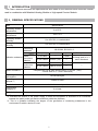
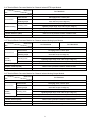
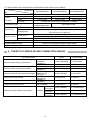
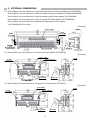
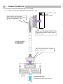
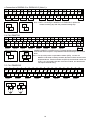
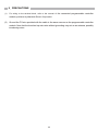
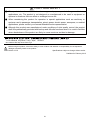
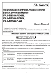
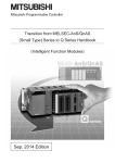
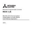
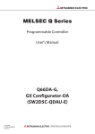
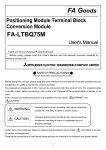
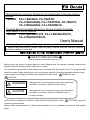
Terminal Block Converter Module for Programmable Controller Analog Module Model FA-LTB40DAG, FA-TB20TD, FA-LTB40ADGN, FA-LTB40TDG, FA-TB20TC, FA-LTB40ADDG, FA-LTB40RD3G Terminal Block Converter Module for Programmable Controller High-speed Counter Module Model FA-LTB40D63P6V5, FA-LTB40D63P6V12, FA-LTB40D63P6V24 User's Manual Thank you for purchasing the FA Goods product. Before using the product, please read this User’s Manual and the relevant manuals carefully to ensure correct use. SAFETY PRECAUTIONS (Always read these precautions prior to use.) Before using this product, please read this User’s Manual and the relevant manuals carefully and handle the product properly with full attention to safety. The precautions presented in this manual are concerned with this product only. For programmable controller system safety precautions, refer to the user's manual of the programmable controller used. In this manual, the safety precautions are classified into two levels: " WARNING" and " CAUTION". WARNING Indicates that incorrect handling may cause hazardous conditions, resulting in death or severe injury. CAUTION Indicates that incorrect handling may cause hazardous conditions, resulting in minor or moderate injury, or property damage. Under some circumstances, failure to observe the precautions given under " CAUTION" may lead to serious consequences. Always follow the precautions of both levels because they are important for personal and system safety. 1 [Design Precautions] WARNING Configure external safety circuits to ensure that the entire system operates safely even when a fault occurs in the external power supply, the programmable controller, or the product. Failure to do so may result in an accident due to an incorrect output or malfunction. (1) Configure external safety circuits, such as an emergency stop circuit, protection circuit, and protective interlock circuit for forward/reverse operation or upper/lower limit positioning. Configure a circuit to turn on the programmable controller and then the external power supply. If the external power supply is turned on first, an accident may occur due to an incorrect output or malfunction. [Design Precautions] CAUTION Precautions for the Terminal Block Converter Module for Analog Module Do not bundle the control lines or communication cables together with the main circuit lines or power cables. Keep a distance of 100mm (3.94 inches) or more between them. Failure to do so may result in a malfunction due to noise. At power on/off, voltage or current may be instantaneously output from the output terminal of this product. In such a case, wait until the analog output becomes stable, and then start controlling the external device. Precautions for the Terminal Block Converter Module for High-speed Counter Module Do not bundle the control lines or communication cables together with the main circuit lines or power cables. Keep a distance of 150mm (5.91 inches) or more between them. Failure to do so may result in a malfunction due to noise. [Installation Precautions] WARNING Be sure to shut off the external power supply for the system in all phases before installation. Failure to do so may result in an electric shock. 2 [Installation Precautions] CAUTION Use the product in an environment that meets the general specifications described in this User’s Manual. Failure to do so may result in an electric shock, fire, malfunction, or the product damage or deterioration. Securely fix the product with a DIN rail or mounting screws. Incorrect mounting may cause the product to malfunction, fail, or drop. When using the product in a vibration environment, secure the product by screws. Tighten the screws within the specified torque range. Undertightening can cause the product to drop, short circuit or malfunction. Overtightening can damage screws and/or the product, causing the product to drop, short circuit, or malfunction. Be sure to shut off the external power supply for the system in all phases before installing or removing the product. Failure to do so may damage the product, or cause the product to malfunction or fail. Do not directly touch any conductive parts and electronic components of the product. Doing so can cause the product to malfunction or fail. [Wiring Precautions] WARNING Be sure to shut off the external power supply for the system in all phases before installation and wiring. Failure to do so may cause an electric shock, or damage the product. 3 [Wiring Precautions] CAUTION Be sure to ground the FG terminal to the protective ground conductor dedicated to the programmable controller with a ground resistance of 100 Ω or less. Failure to do so may result in an electric shock or malfunction. Use applicable solderless terminals and tighten them within the specified torque range. If any spade solderless terminal is used, it may be disconnected when the terminal screw comes loose, resulting in failure. Check the rated voltage and terminal layout, and then wire the product correctly. Connecting a power supply with a different voltage rating or incorrect wiring may cause a fire or failure. Place the cables in a duct or clamp them; if not, dangling cables may swing or be inadvertently pulled,, resulting in damage to the product or cables, or a malfunction due to poor connection. Tighten the terminal screws within the specified torque range. Undertightening can cause a short circuit, fire, or malfunction. Overtightening can damage screws and/or the product, causing the product to drop, short circuit, or malfunction. Tighten the connector screws within the specified torque range. Undertightening can cause a short circuit, fire, or malfunction. Overtightening can damage screws and/or the product, causing the product to drop, short circuit, or malfunction. Connect the connector to the product securely. Failure to do so may cause a malfunction. When disconnecting a cable from the product, do not pull the cable itself. For a cable with connector, hold the connector and pull it out. For a cable connected to a terminal block, loosen the terminal block screws before removing the cable. Failure to do so may result in a malfunction or damage to the product or cable. Before connecting the cables, check the type of interface to be connected. Connecting the cables to a wrong interface or erroneous wiring may cause the product or external devices to fail. Prevent foreign matter such as dust or wire chips from entering the product. Such foreign matter can cause a fire, failure, or malfunction. The product must be installed inside the control panel. Connect the main power supply to the product inside the control panel through a relay terminal block. Only qualified service personnel with knowledge of protection against electric shock should replace and wire the product. When connecting the product to the programmable controller, check that the product configuration is correct. The modules may be failure or malfunction if the configuration is incorrect. Use the product with no pressure applied to its connector. Failure to do so may cause a breakdown or disconnection. 4 Precautions for the Terminal Block Converter Module for Analog Module Do not install the control lines or communication cables together with the main circuit lines or power cables. Keep a distance of 100mm (3.94 inches) or more between them. Failure to do so may result in a malfunction due to noise. Keep a distance of 100mm (3.94 inches) or more between a thermocouple or a resistance temperature sensor and the main circuit line or AC control lines. Also, keep the thermocouple or the resistance temperature sensor away from a circuit that includes harmonics, such as a high-voltage circuit and a load circuit of an inverter. Do not place the product near a device that generates magnetic noise. Precautions for the Terminal Block Converter Module for High-speed Counter Module Do not install the control lines or communication cables together with the main circuit lines or power cables. Keep a distance of 150mm (5.91 inches) or more between them. Failure to do so may result in a malfunction due to noise. [Startup and Maintenance Precautions] WARNING Do not touch any terminal while power is on. Doing so can cause an electric shock or malfunction. Be sure to shut off the external power supply for the system in all phases before cleaning the product or retightening the terminal screws, the mounting screws of the connector, or the fixing screws of the product. Failure to do so may result in an electric shock, or cause the product to fail or malfunction. Undertightening can cause the product to drop, short circuit, or malfunction. Overtightening can damage the screw and/or product, causing the product to drop, short circuit, or malfunction. [Startup and Maintenance Precautions] CAUTION Do not disassemble or modify the product. Doing so may cause a failure, malfunction, injury, or fire. Use any radio communication device such as a cellular phone or PHS (Personal Handy phone System) more than 25cm (9.85 inches) away from the programmable controller and the product in all directions. Failure to do so may cause a malfunction. Be sure to shut off the external power supply for the system in all phases before installing or removing the product. Failure to do so may damage the product, or cause the product to fail or malfunction. After the first use of the product, do not mount or remove the product or cables more than 50 times (IEC 61131-2 compliant). Exceeding the limit of 50 times may cause a malfunction. Only qualified service personnel with knowledge of protection against electric shock should start up or service the product in the control panel. Lock the control panel so that only qualified service personnel can operate it. Before handling the product, always touch a conducting object such as a grounded metal to discharge the static electricity from the human body. Failure to do so may cause the product to fail or malfunction. 5 [Disposal Precautions] CAUTION When disposing this product, treat it as industrial waste. [Transportation Precautions] CAUTION Avoid the shock that exceeds the shock resistance described in the general specifications during transportation, as the product is a precision device. Failure to do so can cause the product to fail. EMC and Low Voltage Directives Compliance with the EMC Directive, which is one of the EU Directives, has been mandatory for the products sold in European countries since 1996. Additionally, compliance with the Low Voltage Directive, another EU Directive, has also been mandatory since 1997. To prove the compliance with the EMC Directive and the Low Voltage Directive, manufactures must issue an EC Declaration of Conformity and the products must bear a CE marking. (1) Compliant products Terminal Block Converter Module for High-speed Counter Module : FA-LTB40D63P6V12, FA-LTB40D63P6V24 (2) Authorized representative in Europe The authorized representative in Europe is shown below. Name: Mitsubishi Electric Europe B.V. Address: Gothaer strasse 8, 40880 Ratingen, Germany (3) How to use the FA Goods in compliance with the EMC and Low Voltage Directives For information on how to conform to the EMC and Low Voltage Directives when incorporating the compliant FA Goods into a user's machinery or system, refer to "EMC and Low Voltage Directives Compliant Manual_50D-FA9010-108". 6 1.INTRODUCTION This User’s Manual describes the specifications and others of the terminal block converter module used in combination with Mitsubishi Analog Module or High-speed Counter Module. 2.GENERAL SPECIFICATIONS Item Specifications Operating ambient temperature 0 to 55°C Storage ambient temperature -25 to 75°C Operating ambient humidity 5 to 95% RH, no condensation Storage ambient humidity 5 to 95% RH, no condensation Conforming standards Under Vibration resistance intermittent vibration Under continuous vibration Shock resistance JIS B 3502, IEC61131-2 Frequency Acceleration Amplitude 5 to 8.4Hz ― 3.5mm 2 8.4 to 150Hz 9.8m/s (1G) ― 5 to 8.4Hz ― 1.75mm 8.4 to 150Hz 4.9m/s2 (0.5G) ― 10 times each in X, Y, and Z directions ― Compliant with JIS B 3502 and IEC61131-2 (147m/s2 (15G), 3 times each in X, Y, and Z directions) Operating atmosphere No corrosive gas Operating altitude (*1) 2,000m or lower Installation location Sweep count Inside the control panel Overvoltage category (*2) II or lower Pollution level (*3) 2 or lower *1: Do not use or store the module under the atmospheric pressure greater than that at an altitude of 0m. *2: Indicates the section of the power supply to which the equipment is assumed to be connected, between the public power grid and the machinery within the premises. *3: This is a guideline indicating the degree of the generation of conducting substances in the environment in which a device is used. 7 3.PERFORMANCE SPECIFICATIONS 3-1. Terminal Block Converter Module for Channel Isolated Thermocouple Input Module Model name FA-LTB40TDG Item Connectable module Terminal screw Terminal block Applicable wire, Tightening torque Module mounting Mounting screw DIN rail Withstand voltage Insulation resistance (initial) Weight Q68TD-G-H01, Q68TD-G-H02, R60TD8-G M3 regular screw, 7.62mm pitch 0.3 to 2mm2 (with solderless terminal) 50 to 75N・cm (5.2 to 7.6kgf・cm) M4 x 0.7mm x 8mm or greater Tightening torque range: 78 to 118N・cm (8 to 12kgf・cm) Applicable DIN rail: TH35-7.5Fe, TH35-7.5Al (IEC60715 compliant) Between analog input CHs: 1000VAC for 1 minute; Other: 500VAC for 1 minute 10MΩ or more by 500VDC insulation resistance tester About 200g 3-2. Terminal Block Converter Module for Thermocouple Input Module Model name FA-TB20TD Item Connectable module Terminal screw Terminal block Applicable wire, Tightening torque Module mounting Mounting screw DIN rail Cold junction compensation resistor Withstand voltage Insulation resistance (initial) Weight Q64TD, Q64TDV-GH M3 captive screw, 7.62mm pitch 0.3 to 2mm2(with solderless terminal), 58.8 to 88.2N・cm (6 to 9kgf・cm) M4 x 0.7mm x 22mm or greater Tightening torque range: 78 to 118N・cm (8 to 12kgf・cm) Applicable DIN rail: TH35-7.5Fe, TH35-7.5Al (IEC60715 compliant) Supplied with the module 1500VAC (50/60Hz) for 1 minute 100MΩ or more by 500VDC insulation resistance tester 125g 3-3. Terminal Block Converter Module for Temperature Control Module Model name FA-TB20TC Item Connectable module Q64TCTTN, Q64TCTTBWN, Terminal screw Terminal block Module mounting M3 captive screw, 7.62mm pitch 0.3 to 2mm2(with solderless terminal), 58.8 to 88.2N・cm (6 to 9kgf・cm) Applicable wire, Tightening torque Mounting screw DIN rail M4 x 0.7mm x 22mm or greater Tightening torque range: 78 to 118N・cm (8 to 12kgf・cm) Applicable DIN rail: TH35-7.5Fe, TH35-7.5Al (IEC60715 compliant) Cold junction compensation resistor Built in the module Withstand voltage Insulation resistance (initial) 1500VAC (50/60Hz) for 1 minute 100MΩ or more by 500VDC insulation resistance tester Weight 125g 8 3-4. Terminal Block Converter Module for Channel Isolated RTD Input Module Model name FA-LTB40RD3G Item Connectable module Q68RD3-G, R60RD8-G Terminal screw M3 regular screw, 7.62mm pitch 0.3 to 2mm2(with solderless terminal), 50 to 75N・cm (5.2 to 7.6kgf・cm) Applicable wire, Tightening torque Terminal block Mounting screw Module mounting DIN rail M4 x 0.7mm x 8mm or greater Tightening torque range: 78 to 118N・cm (8 to 12kgf・m) Applicable DIN rail: TH35-7.5Fe, TH35-7.5Al (IEC60715 compliant) Withstand voltage Between analog input CHs: 1000VAC for 1 minute, Other: 500VAC for 1 minute Insulation resistance (initial) 10MΩ or more by 500VDC insulation resistance tester Weight About 200g 3-5. Terminal Block Converter Module for Channel Isolated Analog Input Module Model name Item Connectable module FA-LTB40ADGN FA-LTB40ADDG Q68AD-G, R60AD8-G, R60AD16-G Q66AD-DG Terminal screw Applicable wire, Tightening torque Terminal block Mounting screw Module mounting DIN rail M3 regular screw, 7.62mm pitch 0.3 to 2mm2(with solderless terminal), 50 to 75N・cm (5.2 to 7.6kgf・cm) M4 x 0.7mm x 8mm or greater Tightening torque range: 78 to 118N・cm (8 to 12kgf・cm) Applicable DIN rail: TH35-7.5Fe, TH35-7.5Al (IEC60715 compliant) Withstand voltage Between CHs: 1000VAC for 1 minute, Other: 500VAC for 1 minute Insulation resistance(initial) 10MΩ or more by 500VDC insulation resistance tester Weight About 200g 3-6. Terminal Block Converter Module for Channel Isolated Analog Output Module Model name FA-LTB40DAG Item Connectable module Terminal block Module mounting Q66DA-G, R60DA8-G, R60DA16-G Terminal screw Applicable wire, Tightening torque Mounting screw DIN rail Withstand voltage Insulation resistance(initial) M3 regular screw, 7.62mm pitch 0.3 to 2mm2(with solderless terminal), 50 to 75N・cm (5.2 to 7.6kgf・cm) M4 x 0.7mm x 8mm or greater Tightening torque range: 78 to 118N・cm (8 to 12kgf・cm) Applicable DIN rail: TH35-7.5Fe, TH35-7.5Al (IEC60715 compliant) Between CHs: 1000VAC for 1 minute, Other: 500VAC for 1 minute 10MΩ or more by 500VDC insulation resistance tester Accessory Marking strip for R60DA8-G / R60DA16-G Weight About 200g 9 3-7. Terminal Block Converter Module for Multichannel High-speed Counter Module Model name Item FA-LTB40D63P6V5 FA-LTB40D63P6V12 Connectable module Counter input signal QD63P6 Voltage 5V±10% 12V±10% 24V±10% Current 6.4 to 11.5mA 10.8 to 15.9mA 10.5 to 14.9mA Pulse width Module mounting Compliant with the performance specifications of QD63P6 Open collector output, CMOS voltage output Connectable encoder Terminal block FA-LTB40D63P6V24 Terminal screw Applicable wire, Tightening torque Mounting screw DIN rail Open collector output M3 regular screw, 7.62mm pitch 0.3 to 2mm2(with solderless terminal), 50 to 75N・cm (5.2 to 7.6kgf・cm) M4 x 0.7mm x 8mm or greater Tightening torque range: 78 to 118N・cm (8 to 12kgf・cm) Applicable DIN rail: TH35-7.5Fe, TH35-7.5Al (IEC60715 compliant) Withstand voltage 500VAC for 1 minute Insulation resistance (initial) 10MΩ or more by 500VDC insulation resistance tester Weight About 200g 4.TARGET PLC MODULES AND CONNECTION CABLES Connection Cable Model PLC Module Model Channel Isolated Analog Input Module Channel Isolated Analog Output Module Channel Isolated Thermocouple Input Module Thermocouple Input Module Channel Isolated RTD Input Module Temperature Control Module Multichannel High-Speed Counter Module Q68AD-G R60AD8-G R60AD16-G Q66AD-DG Q66DA-G R60DA8-G R60DA16-G Q68TD-G-H01 Q68TD-G-H02 R60TD8-G Q64TD Q64TDV-GH Q68RD3-G R60RD8-G Q64TCTTN Q64TCTTBWN 5V input signal 12V QD63P6 input signal 24V input signal 10 Module Model FA-CBL**Q68ADGN FA-LTB40ADGN FA-CBL**Q66ADDG FA-CBL**Q66DAG FA-LTB40ADDG FA-LTB40DAG FA1-CBL**R60DA8G FA-LTB40DAG FA-CBL**Q68TDG FA-LTB40TDG FA-CBLQ64TD** FA-TB20TD FA-CBL**Q68RD3G FA-LTB40RD3G FA-CBLQ64TC** FA-TB20TC FA-CBL**QD63P6 FA-LTB40D63P6V5 FA-CBL**QD63P6 FA-LTB40D63P6V12 FA-CBL**QD63P6 FA-LTB40D63P6V24 5.EXTERNAL DIMENSIONS 5-1. Terminal Block Converter Module for Channel Isolated Thermocouple Input Module (FA-LTB40TDG) Terminal Block Converter Module for Channel Isolated Analog Input Module (FA-LTB40ADGN/ADDG) Terminal Block Converter Module for Channel Isolated Analog Output Module (FA-LTB40DAG) Terminal Block Converter Module for Channel Isolated RTD Input Module (FA-LTB40RD3G) Terminal Block Converter Module for Multichannel High-speed Counter Module (FA-LTB40D63P6V5/V12/V24) [Unit:mm] 5-2. Terminal Block Converter Module for Thermocouple Input Module (FA-TB20TD) [Unit:mm] 5-3. Terminal Block Converter Module for Temperature Control Module (FA-TB20TC) [Unit:mm] 11 6.CONNECTING METHOD 6-1 Connection to the terminal block type PLC module 6-1-1. When a connection cable with terminal block is used Q64TD RUN ERR. Ground the FG wire in the same manner as the programmable controller module. (FA-CBLQ64TC** only.) Programmable controller module Q64TD or others Q64TD Fully install the terminal block to the programmable controller module using the mounting screws. Connection cable FA-CBLQ64TD** FA-CBLQ64TC** Fully insert and secure the connector until you hear a click. Thermocouple input Temperature control input/output 12 6-2. Connection to the connector type PLC module 6-2-1. When a connector cable with FG wire on both ends is used Q68AD-G RUN ALM ERR. A/D -10~10V 0~20mA Ground the FG wire in the same manner as the programmable controller module. Programmable controller module Q68AD-G or others Q68AD-G Insert the connector as far as it goes, and then fully install the connector to the programmable controller module using the mounting screws. Connection cable FA-CBL**Q68ADGN FA-CBL**Q66ADDG FA-CBL**Q66DAG FA-CBL**Q68TDG FA-CBL**Q68RD3G FA1-CBL**R60DA8G Ground the FG wire in the same manner as the programmable controller module. Insert the connector as far as it goes, and then secure the connector with the clip. Voltage/Current input/output Dual wire transmitter input Thermocouple input RTD input 13 6-2-2. When a connector cable with FG wire on one end is used Programmable controller module QD63P6 QD63P6 RUN 1 ERR. Insert the connector as far as it goes, and then fully install the connector to the programmable controller module using the mounting screws. 2 3 4 5 6 CH f A f B QD63P6 Connection cable FA-CBL**QD63P6 Ground the FG wire in the same manner as the programmable controller module. Insert the connector as far as it goes, and then secure the connector with a clip. FA-LTB40D63P6V5 Pulse input 14 7.EXTERNAL CONNECTION EXAMPLE 7-1. FA-LTB40ADGN 1 CH1 V+ 3 CH1 Is 2 CH1 V-/I- 5 CH2 V+ 4 CH1 I+ 7 CH2 Is 6 CH2 V-/I- Input1 9 11 13 15 17 19 21 23 25 27 29 31 33 35 37 39 CH3 CH3 CH4 CH4 CH5 CH5 CH6 CH6 CH7 CH7 CH8 CH8 V+ Is V+ Is V+ Is V+ Is V+ Is V+ Is 10 12 14 16 18 20 22 24 26 28 30 32 34 36 38 40 CH3 CH3 CH4 CH4 CH5 CH5 CH6 CH6 CH7 CH7 CH8 CH8 V-/II+ V-/II+ V-/I I+ V-/II+ V-/II+ V-/II+ - 8 CH2 I+ Input2 Current input(Note 1) V+ Input3 V+ I+ I- I+ Input5 Input6 Input7 Input8 Voltage input(Note 2) Note 1: For current input, connect the (V+) and (Is) terminals. The screw terminal Is V-/I- Input4 block short circuit bar FA-BAR20P can be used for the above connection. (For details of the screw terminal block short circuit bar, refer to our catalog.) Note 2: For voltage input, set the (Is) and (I+) terminals as NC, and do not connect the terminals to external wiring. Is V-/I- I+ V+ V- 7-2. FA-LTB40ADDG 1 CH1 P 3 5 I/CHK 2 4 I+ /CHK 7 CH2 P 9 11 13 15 17 19 21 23 25 27 29 31 33 35 37 39 ICH3 ICH4 ICH5 ICH6 IDC24V P /CHK P /CHK P /CHK /CHK P /CHK 8 10 12 14 16 18 20 22 24 26 28 30 32 34 36 38 40 I+ I+ I+ I+ I+ - DC24G /CHK /CHK /CHK /CHK /CHK 6 - Input1 Input2 Input3 P I-/CHK I+/CHK + - Dual wire transmitter Input5 Input6 24VDC Current input Dual wire transmitter input P Input4 I-/CHK I+/CHK + - I+ I- V 7-3. FA-LTB40DAG < Connection to Q66DA-G > 1 CH1 V+ 3 CH1 I+ 5 7 CH2 V+ - 9 CH2 I+ 11 - 2 4 6 8 10 COM1 - - COM2 - Output1 I+ COM V+ V- - Output2 Voltage output V+ 13 15 17 19 21 23 25 27 29 31 33 35 37 39 CH3 CH3 CH4 CH4 CH5 CH5 CH6 CH6 DC24V V+ I+ V+ I+ V+ I+ V+ I+ 12 14 16 18 20 22 24 26 28 30 32 34 36 38 40 COM3 Output3 - - COM4 Output4 Current output V+ I+ COM I- I+ 15 - - COM5 Output5 - - COM6 Output6 - - - DC24G 24VDC < Connection to R60DA8-G or R60DA16-G (Note 1)> 1 CH1 V+/I+ 3 2 CH1 V-/I- 5 7 CH2 V+/I+ 4 6 CH2 V-/I- Output1 Output2 - 9 11 13 15 17 19 21 23 25 27 29 31 33 35 37 39 CH3 CH4 CH5 CH6 CH7 CH8 DC V+/I+ V+/I+ V+/I+ V+/I+ V+/I+ V+/I+ 24V 8 10 12 14 16 18 20 22 24 26 28 30 32 34 36 38 40 CH3 CH4 CH5 CH6 CH7 CH8 DC V-/IV-/IV-/IV-/IV-/IV-/I24G Output3 Voltage output Output4 Current output V+/I+ V+/I+ V-/I- Output5 Output6 Output7 Output8 24VDC Note 1: When connecting the R60DA8-G or R60DA16-G, replace the module’s marking strip with the provided marking strip. V-/II+ I- V+ V- 7-4. FA-LTB40TDG 1 CH1 + 3 5 CH2 + - 2 CH1 - 4 9 CH3 + - 6 CH2 - - Input1 7 8 - Input3 Input4 Input5 Input6 Input7 Input8 RTD · Install the module in a location having a constant ambient temperature. RTD input · Connect the thermocouple or compensation lead wire directly to the terminal RTDG block. (Note1) Thermocouple input + + 13 15 17 19 21 23 25 27 29 31 33 35 37 39 CH4 CH5 CH6 CH7 CH8 RTD + + + + + G 12 14 16 18 20 22 24 26 28 30 32 34 36 38 40 CH4 CH5 CH6 CH7 CH8 RTD RTD + - 10 CH3 - - Input2 11 - RTD+ RTD- - RTD (Note1) Note 1: For the cold junction compensation resistor (RTD), connect the Q68TD-G-H01/H02 accessory between terminal numbers 38 and 40 as illustrated above. Terminal number 38 (RTD G) and terminal number 40 (RTD -) are connected inside the conversion module, and therefore do not require external wiring. 7-5. FA-LTB40RD3G 1 CH1 A1 3 CH1 b1 2 CH1 B1 5 4 - Input1 7 CH2 B2 6 CH2 A2 9 11 13 15 17 19 21 23 25 27 29 31 33 35 37 39 CH3 CH3 CH4 CH5 CH5 CH6 CH7 CH7 CH8 A3 b3 B4 A5 b5 B6 A7 b7 B8 10 12 14 16 18 20 22 24 26 28 30 32 34 36 38 40 CH3 CH4 CH4 CH5 CH6 CH6 CH7 CH8 CH8 B3 A4 b4 B5 A6 b6 B7 A8 b8 - 8 CH2 b2 Input2 Input3 Input4 Input5 RTD input A B b B A B b A b A B b 16 Input6 Input7 Input8 7-6. FA-TB20TD Input2 1 3 5 7 - - - SLD 2 RTD + 4 RTD - 6 9 CH2 + 8 CH1 + SLD RTD 11 13 15 17 19 CH2 CH4 CH4 SLD + 10 12 14 16 18 20 CH1 CH3 CH3 SLD + - Input1 Thermocouple input + Input4 Input3 RTD input RTD+ RTDRTD - + (Note1) · Install the module in a location having a constant ambient temperature. · Connect the thermocouple or compensation lead wire directly to the terminal block. · For FA-CBLQ64TD**, a ground wire is not wired. Grounding with FA-TB20TD is not possible. Ground Q64TD to terminal number 18 on the terminal block of FA-CBLQ64TD** that is connected to the programmable controller module. Note 1: The cold junction compensation resistor (RTD) is supplied with FA-TB20TD. 7-7. FA-TB20TC Input1 Control output 1 3 L1 5 COM - L3 7 CH1 + 2 4 6 L2 L4 - Control output Thermocouple input + - + - Input3 9 CH1 - 8 CH2 + 15 17 19 CH3 CH3 + 10 12 14 16 18 20 CH2 CH4 CH4 + - Input2 11 13 Input4 · Install the module in a location having a constant ambient temperature. · Connect the thermocouple or compensation lead wire directly to the terminal block. · The cold junction compensation resistor (RTD) is built into FA-TB20TC. 17 7-8. FA-LTB40D63P6V** <FA-LTB40D63P6V5 (For 5V signal)> 1 - 3 5 7 CH1 CH1 A+(5) B+(5) 2 4 6 CH1 CH1 AB- 9 11 13 15 17 19 21 23 25 27 29 31 33 35 37 39 CH2 CH2 CH3 CH3 CH4 CH4 CH5 CH5 CH6 CH6 A+(5) B+(5) A+(5) B+(5) A+(5) B+(5) A+(5) B+(5) A+(5) B+(5) 8 10 12 14 16 18 20 22 24 26 28 30 32 34 36 38 40 CH2 CH2 CH3 CH3 CH4 CH4 CH5 CH5 CH6 CH6 ABABABABAB- Input1 Input2 Input3 Input4 Input5 Input6 <FA-LTB40D63P6V12 (For 12V signal)> 1 - 3 5 7 CH1 CH1 A+(12) B+(12) 2 4 6 CH1 CH1 AB- 9 11 13 15 17 19 21 23 25 27 29 31 33 35 37 39 CH2 CH2 CH3 CH3 CH4 CH4 CH5 CH5 CH6 CH6 A+(12) B+(12) A+(12) B+(12) A+(12) B+(12) A+(12) B+(12) A+(12) B+(12) 8 10 12 14 16 18 20 22 24 26 28 30 32 34 36 38 40 CH2 CH2 CH3 CH3 CH4 CH4 CH5 CH5 CH6 CH6 ABABABABAB- Input1 Input2 Input3 Input4 Input5 Input6 <FA-LTB40D63P6V24 (For 24V signal)> 1 - 3 5 7 CH1 CH1 A+(24) B+(24) 2 4 6 CH1 CH1 AB- 9 11 13 15 17 19 21 23 25 27 29 31 33 35 37 39 CH2 CH2 CH3 CH3 CH4 CH4 CH5 CH5 CH6 CH6 A+(24) B+(24) A+(24) B+(24) A+(24) B+(24) A+(24) B+(24) A+(24) B+(24) 8 10 12 14 16 18 20 22 24 26 28 30 32 34 36 38 40 CH2 CH2 CH3 CH3 CH4 CH4 CH5 CH5 CH6 CH6 ABABABABAB- Input1 Input2 Input3 Input4 Pulse input A+ B+ A- B- + - + Phase A Phase B 18 Input5 Input6 8.APPLICABLE SOLDERLESS TERMINALS Note 1: This solderless terminal is suitable to captive screws only. Do not apply the terminal to regular screws. ● Solderless terminal dimensions Round non-insulated solderless terminal Y non-insulated solderless terminal [Unit: mm] Round insulated solderless terminal Y insulated solderless terminal ● Terminal block shape [Unit: mm] Captive screw Regular screw 19 9.PRECAUTIONS (1) For wiring to the terminal block, refer to the manual of the connected programmable controller module, published by Mitsubishi Electric Corporation. (2) Ground the FG wire provided with the cable in the same manner as the programmable controller module. Note that the bunched-up extra wire without grounding may act as an antenna, possibly introducing noise. 20 FOR YOUR SAFETY This product has been manufactured as a general-purpose product for general industry applications, etc. The product is not designed or manufactured to be used in equipment or systems in situations that can affect or endanger human life. When considering this product for operation in special applications such as machinery or systems used in passenger transportation, atomic power, electric power, aerospace, or medical applications, please contact your nearest Mitsubishi sales representative. Although this product was manufactured under conditions of strict quality control, the product shall be systematically provided with backup and fail-safe functions when it is used in facilities where breakdowns of the product are likely to cause a serious accident or damage. 1-13-5 Kudankita, Chiyoda-ku, Tokyo, Japan 102-8404 Our website URL http://www.mee.co.jp/ Before using this product, ensure the safety in case of failure. We assume no responsibility for consequential damages caused by failure of the product. 50D-FA9010-127-B Specifications subject to change without notice. Published in February 2015 21