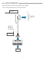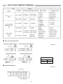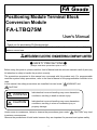
1
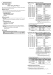
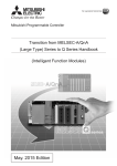
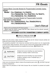
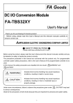
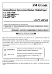
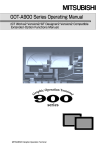
Positioning Module Terminal Block Conversion Module FA-LTBQ75M User's Manual Thank you for purchasing FA Goods product. Before using, please read this User’s Manual and the relevant manuals carefully to ensure correct use. SAFETY PRECAUTIONS (Always read these precautions prior to use.) Before using this product, please read this User’s Manual and the relevant manuals carefully and pay full attention to safety to handle the product correctly. The precautions presented in this manual are concerned with this product only. For programmable controller system safety precautions, refer to the User’s Manual of the programmable controller to be used. In this manual, the safety precautions are classified into two levels: " WARNING" and " CAUTION". WARNING Indicates that incorrect handling may cause hazardous conditions, resulting in death or severe injury. CAUTION Indicates that incorrect handling may cause hazardous conditions, resulting in minor or moderate injury or property damage. Under some circumstances, failure to observe the precautions given under " CAUTION" may lead to serious consequences. Observe the precautions of both levels because they are important for personal and system safety. 1 [Design Precautions] WARNING Configure safety circuits external to the programmable controller to ensure that the entire system operates safely even when a fault occurs in the external power supply or the programmable controller, this product. Failure to do so may result in an accident due to an incorrect output or malfunction. (1) Configure external safety circuits, such as an emergency stop circuit, protection circuit, and protective interlock circuit for forward/reverse operation or upper/lower limit positioning. Configure a circuit so that the programmable controller is turned on first and then the external power supply. If the external power supply is turned on first, an accident may occur due to an incorrect output or malfunction. [Design Precautions] CAUTION Do not install the control lines or communication cables together with the main circuit lines or power cables. Keep a distance of 100mm (3.94 inches) or more between them. Failure to do so may result in malfunction due to noise. [Installation Precautions] WARNING Shut off the external power supply (all phases) before installation. Failure to do so may result in electric shock. [Installation Precautions] CAUTION Use the programmable controller in an environment that meets the general specifications in this User’s Manual. Failure to do so may result in electric shock, fire, malfunction, or damage to or deterioration of the product. Securely fix the module with a DIN rail or mounting screws. Incorrect mounting may cause malfunction, failure or drop of the module. When using this product in an environment of frequent vibrations, fix the module with a screw. Tighten the screw within the specified torque range. Undertightening can cause drop of the screw, short circuit or malfunction. Overtightening can damage the screw and/or module, resulting in drop, short circuit, or malfunction. Shut off the external power supply for the system in all phases before mounting or removing the module. Failure to do so may result in damage to, malfunction, or failure of the product. Do not directly touch any conductive parts and electronic components of this product. Doing so can cause malfunction or failure of the product. 2 [Wiring Precautions] WARNING Shut off the external power supply for the system in all phases before installation and wiring. After wiring, attach the included terminal cover to the module before turning it on for operation. Failure to do so may result in electric shock. [Wiring Precautions] CAUTION Use applicable solderless terminals and tighten them within the specified torque range. If any spade solderless terminal is used, it may be disconnected when the terminal screw comes loose, resulting in failure. Check the rated voltage and terminal layout before wiring to the module, and connect the cables correctly. Connecting a power supply with a different voltage rating or incorrect wiring may cause a fire or failure. Do not install the control lines or communication cables together with the main circuit lines or power cables. Keep a distance of 100mm (3.94 inches) or more between them. Failure to do so may result in malfunction due to noise. Place the cables in a duct or clamp them. If not, dangling cables may swing or inadvertently be pulled, resulting in damage to the module or cables or malfunction due to poor connection. Tighten the terminal screw within the specified torque range. Undertightening can cause short circuit, fire, or malfunction. Overtightening can damage the screw and/or module, resulting in drop, short circuit, or malfunction. Tighten the connector screws within the specified torque range. Undertightening can cause short circuit, fire, or malfunction. Overtightening can damage the screw and/or module, resulting in drop, short circuit, fire, or malfunction. Install the connector to the module securely. Failure to do so may cause malfunction. When disconnecting the cable from the module, do not pull the cable by the cable part. For a cable with connector, hold the connector by hand and pull it out. For a cable connected to a terminal block, loosen the terminal block screws first before removing the cable. Failure to do so may result in malfunction and damage to the module or cable. Before connecting the cables, check the type of interface to be connected. Connecting or erroneous wiring to the wrong interface may cause failure to the module and external devices. Prevent foreign matter such as dust or wire chips from entering the module. Such foreign matter can cause a fire, failure, or malfunction. This product must be installed to control panels. Connect the main power supply to this product in the control panel through a relay terminal block. Wiring and replacement of a this product must be performed by qualified service personnel who is familiar with protection against electric shock. When connecting programmable controller, check that the product configuration are correct. The modules may be failure or malfunction if the configuration is incorrect. Use it with power doesn't join the connector of this product. Failure or disconnection may cause malfunction. 3 [Startup and Maintenance Precautions] WARNING Do not touch any terminal while power is on. Doing so will cause electric shock or malfunction. Shut off the external power supply for the system in all phases before cleaning the module or retightening the terminal screws, connector screws, or module fixing screws. Failure to do so may result in electric shock or cause the module to fail or malfunction. Undertightening can cause drop of the screw, short circuit or malfunction. Overtightening can damage the screw and/or module, resulting in drop, short circuit, or malfunction. [Startup and Maintenance Precautions] CAUTION Do not disassemble or modify the modules. Doing so may cause failure, malfunction, injury, or a fire. Use any radio communication device such as a cellular phone or PHS (Personal Handy phone System) more than 25cm (9.85 inches) away in all directions from the programmable controller, this product. Failure to do so may cause malfunction. Shut off the external power supply for the system in all phases before mounting or removing the module. Failure to do so may cause the module to fail or malfunction or damage. After the first use of the product, do not mount/remove the module, and the cable more than 50 times (IEC 61131-2 compliant) respectively. Exceeding the limit of 50 times may cause malfunction. Startup and maintenance of a control panel must be performed by qualified maintenance personnel with knowledge of protection against electric shock. Lock the control panel so that only qualified maintenance personnel can operate it. Before handling the module, touch a grounded metal object to discharge the static electricity from the human body. Failure to do so may cause the module to fail or malfunction. [Disposal Precautions] CAUTION When disposing of this product, treat it as industrial waste. [Transportation Precautions] CAUTION The shock that exceeds the range of the general specification during transportation must avoid this product for the precision instrument. Doing so results in the risk of failure. 4 1.INTRODUCTION This User’s Manual describes the specifications and so on for terminal block conversion modules used in combination with Mitsubishi Electric Corporation positioning modules. 2.GENERAL SPECIFICATIONS Item Specifications Operating Surrounding air temperature 0 to 55°C Storage ambient temperature -25 to 75°C Operating ambient humidity 5 to 95% RH, no condensation Storage ambient humidity 5 to 95% RH, no condensation Compliant standards Under Vibration resistance intermittent vibration Under continuous vibration Shock resistance JIS B 3502, IEC61131-2 Frequency Acceleration Amplitude 10 to 57Hz ― 0.075mm 2 57 to 150Hz 9.8m/s (1G) ― 10 to 57Hz ― 0.035mm 57 to 150Hz 4.9m/s2 (0.5G) Sweep count 10 times each in X, Y, and Z axis directions ― ― Conforms to JIS B 3502 and IEC61131-2 (147m/s2 (15G), 3 times each in X, Y, and Z axis directions) Operating atmosphere There should be no corrosive gases. Operating altitude (* 1) 2,000m or lower Installation location Inside control panel Overvoltage category (* 2) II or lower Pollution level (* 3) 2 or lower * 1: Do not use or store in a pressurized environment greater than the atmospheric pressure at an altitude of 0m. * 2: Indicates how an assumption has been made on the point at which the devices are connected from the public power grid to the machinery and equipment inside the facilities. * 3: This is a guideline indicating the extent to which conducting substances are found in the environment in which the devices are used. 5 3.PERFORMANCE SPECIFICATIONS Model name Item Number of supported axes Rated voltage Input Rated current signals Used voltage range Terminal block Terminal screw block Applicable wire Module mounting Mounting screws DIN rail Dielectric strength voltage Weight FA-LTBQ75M 2 axes (2 units used for 4 axes) 24 VDC (CLASS 2) 5mA 4.5 to 26.4 VDC (CLASS 2) M3 screws, 7.62 mm pitch Terminal screw tightening torque range: 50 to 75N・cm (5.2 to 7.6kgf·cm) Applicable wire: 0.5 to 1.25mm2 M4 × 0.7mm × 8mm or greater Tightening torque range: 78 to 118N·cm (8 to 12kgf·cm) Applicable DIN rail: TH35-7.5Fe, TH35-7.5Al (conform to JIS C 2812) 500 VAC for 1 minute (between all DC external terminals and earth) About 140g 6 4.CONNECTED TARGET MODEL / PLC MODULE,CONNECTION CABLE PLC Module Model MELSEC-Q Series connector type Cable Model between PLC Module QD75M1 QD75M2 QD75M4 QD75MH1 QD75MH2 FA-CBLQ7 QD75MH4 QD77MS2(Note 1),(Note 2) QD77MS4(Note 1),(Note 2) QD77MS16(Note 1),(Note 2) Module Model Connected Devices FA-LTBQ75M External devices Connection signals For terminal block conversion Note 1: The following signals to connecting differential output type of manual pulse generator/Incremental synchronous encoder will not use. QD77MS**:HAH、HAL、HBH、HBL Note 2: Units shall use to be replaced with signal names as the following. No FA-LTBQ75M QD77MS** Terminal names Signal names 1 PULSER A+ 5V 2 PULSER B+ 5V 3 PULSER A- HA 4 PULSER B- HB 5 P5 5V 6 1.CHG DI1 7 2.CHG DI2 5.EXTERNAL DIMENSIONS [Unit: mm] 7 6.INSTALLATION METHOD Connection example of PLC positioning module and servo amplifier When connected to Mitsubishi Electric Corporation MR-J4 Series コネクタは奥まで挿入し、取付け Attach the terminal block securely ネジにてシーケンサユニットに確 to the PLC module with attachment screws. 実に取付けて下さい。 シーケンサユニット QD75M1他 Programmable controller module QD75M1, other 位置決めー 変換ユニット間 接続ケーブル FA-CBL**Q7 Connection cable between positioning module and conversion module コネクタは奥まで挿入し、 Insert the connector to the 確実に固定してください。 back, and then fully secure the connector with a clip. Manual pulsar, all external signals 手動パルサ、 各種外部信号 8 7.EXTERNAL CONNECTION EXAMPLE Note: The Manual pulse generator please use HR-HDP01 manufactured by Mitsubishi Corporation. (1) When the QD75M connection. Connection example (2) When the QD75MH connection. Connection example (3) When the QD77MS connection. Connection example 9 8.APPLICABLE CRIMPING TERMINALS ● Size of crimping terminal [Unit:mm] Size of crimping terminal ● Terminal trapezoid A B MIN 5.0 MAX 6.3 [Unit:mm] 10 9.Gratis Warranty Terms and Gratis Warranty Range If any fault or defect (hereinafter referred to as “Failure”) attributable to Mitsubishi Electric should occur within the gratis warranty period, Mitsubishi Electric shall replace the product free of charge via the distributor from whom you made your purchase. ●Gratis Warranty Period The gratis warranty period of this product shall be one (1) year from the date of purchase or delivery to the designated place. ●Gratis Warranty Range (1) The gratis warranty range shall be limited to normal use based on the usage conditions, methods and environment, etc., defined by the terms and precautions, etc., given in the instruction manual, user’s manual, and caution labels on the product. (2) In the following cases, a repair fee shall be applied even if within the gratis warranty period. 1) Failure resulting from inappropriate storage or handling, carelessness or negligence by the user, or Failure caused by the user’s hardware or software design. 2) Failure caused by unapproved modifications, etc., to the product by the user. 3) Failure that could have been avoided if, when the Mitsubishi Electric Engineering product was assembled into the user’s device, safeguards defined by legal regulations applicable to the user’s device or functions or structures considered standard by the industry had been provided. 4) Failure recognized as preventable if the consumed products specified in instruction manuals, etc., were normally maintained or replaced. 5) Replacement of consumable parts (relays, etc.). 6) Failure caused by external factors beyond anyone’s control such as fires or abnormal voltage, and Failure caused by Force Majeure such as earthquakes, lightning, or wind and water damage. 7) Failure caused by reasons unpredictable by scientific technology standards at the time of shipment from Mitsubishi Electric Engineering. 8) Any other failure not attributable to Mitsubishi Electric Engineering or found by the user to not be attributable to Mitsubishi Electric Engineering. 10.Exclusion of Opportunity Loss and Secondary Loss from Warranty Liability Regardless of the gratis warranty period, MEE shall not be liable for compensation for damages arising from causes not attributable to MEE, opportunity losses or lost profits incurred by the user due to Failures of MEE products, damages or secondary damages arising from special circumstances, whether foreseen or unforeseen by MEE, compensation for accidents, compensation for damages to products other than MEE products, or compensation for other work carried out by the user. 11 FOR YOUR SAFETY This product has been manufactured as a general-purpose product for general industry applications, etc. The product is not intended for use in devices or systems used under conditions in which human life could be greatly affected. When considering application of this product to special applications, such as nuclear power, electrical power, aerospace, medical, or manned transport devices or systems, contact our sales service desk. Although this product was manufactured under a strict quality management system, the product shall be systematically provided with backup and fail-safe functions when applied to equipment that may lead to a major accident or damage in the unlikely event any failure or defect should occur in the product. 1-13-5 Kudankita, Chiyoda-ku, Tokyo, Japan 102-0073 Homepage URL: http://www.mee.co.jp/ During product use, be sure to ensure safety in the unlikely event failure occurs. Mitsubishi Electric Engineering assumes no responsibility whatsoever for any secondary damage caused by the failure of this product. 50D-FA9010-029-A Information such as specifications is subject to change without notice. Developed March 2014 12