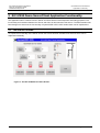
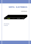
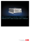
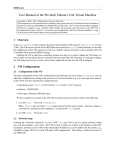
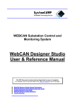
1
SystemCORP Embedded Technology Pty Ltd IEC 61850 Server/Client Application Demo for TQ Systems GmbH STKA28 Development Kit User Manual This PDF Document contains internal hyperlinks for ease of navigation. For example, click on any item listed in the Table of Contents to go to that page. IEC 61850 Server/Client Application Demo for TQ Systems GmbH STKA28 Development Kit Copyright: All rights reserved. None of the information contained in this document may be reproduced or stored in a database or retrieval system or disclosed to others without written authorization by SystemCORP Embedded Technology Pty Ltd. The information in this document is subject to change without prior notice and should not be construed as a commitment by SystemCORP Embedded Technology Pty Ltd. SystemCORP Embedded Technology Pty Ltd do not assume responsibility for any errors, which may be in this document. Documentation Control Author: Version: Version History: Brigid Reilly 1.00 1.00 – Initial release Creation Date: 22 November 2013 Last Version Date: 22 November 2013 Product Reference: Document Status: User Manual – 1.00 500-0041 RELEASED Page 2 of 18 IEC 61850 Server/Client Application Demo for TQ Systems GmbH STKA28 Development Kit Table of Contents 1 Introduction ..................................................................................................................5 2 Installation Guide .........................................................................................................6 2.1 2.2 2.3 2.4 3 What is included in this Demo ..................................................................................................... 6 Minimum requirements ................................................................................................................ 6 Installation Instructions ................................................................................................................ 6 Development Guidelines ............................................................................................................. 7 IEC 61850 Demo Server/Client Application Functionality ............................................8 3.1 3.1.1 3.1.2 3.1.3 3.1.4 3.1.5 3.1.6 3.2 3.2.1 3.2.2 3.2.3 3.2.4 3.2.5 The Server Screen ...................................................................................................................... 8 Update Analog Inputs.................................................................................................................. 9 Set Alarm Threshold ................................................................................................................... 9 Single Point Control on Server (SPCO) ..................................................................................... 10 Indications - Server Side ........................................................................................................... 10 Double Point Control ................................................................................................................. 10 Stop, Free and Exit ................................................................................................................... 11 The Client Screen ..................................................................................................................... 12 Read from Server...................................................................................................................... 12 Read Alarm Threshold .............................................................................................................. 13 Indications – Client Side ............................................................................................................ 13 Client Control - Single Control Point .......................................................................................... 13 Client Control - Double Point Control ......................................................................................... 14 3.2.5.1 Warning Message ..................................................................................................... 14 3.2.6 Stop/Free Exit ........................................................................................................................... 15 4 Appendix ...................................................................................................................16 4.1.1 4.1.2 4.1.3 4.1.4 PIS-10 Object Management Functions ...................................................................................... 16 PIS-10 Data Attributes Access Functions .................................................................................. 16 PIS-10 Control Functions .......................................................................................................... 16 IEC 61850 PIS-10 API Overview ............................................................................................... 17 Table of Figures Figure 1: The IEC 61850 Server Demo Screen .................................................................................................... 8 Figure 2: Update Analog Inputs ........................................................................................................................... 9 Figure 3: Set Alarm Threshold ............................................................................................................................. 9 Figure 4: Single Point Control Server Screen ..................................................................................................... 10 Figure 5: Indication switch on Server ................................................................................................................. 10 Figure 6: Double Point Control on Server........................................................................................................... 11 Figure 7: Stop, Free and Exit on Server ............................................................................................................. 11 Figure 8: The IEC 61850 Client Demo Screen ................................................................................................... 12 Figure 9: Read from Server ............................................................................................................................... 12 Figure 10: Read Alarm Threshold ...................................................................................................................... 13 Figure 11: Indications Client side ....................................................................................................................... 13 Figure 12: Client Control - Single Point Control .................................................................................................. 13 Figure 13: Client Control - Double Point Control................................................................................................. 14 Figure 14: Warning Message- Confirm Action (XCBR) ....................................................................................... 14 Figure 15: Warning Message- Confirm Action (CSWI) ....................................................................................... 15 Figure 16: PIS-10 API Overview Server ............................................................................................................. 17 Figure 17: PIS-10 API Overview Server - Controls ............................................................................................. 18 Figure 18: PIS-10 API Overview - Client (Controls) ............................................................................................ 18 User Manual – 1.00 Page 3 of 18 IEC 61850 Server/Client Application Demo for TQ Systems GmbH STKA28 Development Kit List of Tables Table 1: XCBR /CSWI positon meaning............................................................................................................. 11 Table 2: PIS-10 Object Management Functions ................................................................................................. 16 Table 3: PIS-10 Data Attributes Access Functions ............................................................................................. 16 Table 4: PIS-10 Control Functions ..................................................................................................................... 16 User Manual – 1.00 Page 4 of 18 IEC 61850 Server/Client Application Demo for TQ Systems GmbH STKA28 Development Kit Introduction 1 Introduction The STKA28 Development Kit contains both hardware and software components required for a basic development. This document will introduce you to the basics of the standard IEC 61850 and using the STKA28. This Manual gets you started with creating an IEC 61850 application with your STKA28. This document is intended for those with a basic to intermediate knowledge of IEC 61850. The Demo shows the implementation of SystemCORP 61850 PIS-10 stack on TQ Systems GmbH STKA28 and how to integrate this with your application. This manual will outline how to get started with IEC 61850 Server/Client Application Demo. This Demo has been created for developer’s who wish to start writing IEC 61850 applications to run on TQ Systems GmbH STKA28. Further information on IEC 61850 standards can be found in the Appendix. User Manual – 1.00 Page 5 of 18 IEC 61850 Server/Client Application Demo for TQ Systems GmbH STKA28 Development Kit Installation Guide 2 Installation Guide Basic Definitions: PC : PC Blue Power 28: Qtcreator: refers to host Linux PC refers to the touch screen STKA28 Starter kit is a common developer’s tool 2.1 What is included in this Demo Demo package includes: A Qt application executable which can be run on the Host Linux PC which is based on Ubuntu11.10 (QtServerDemoPc, QtClientDemoPc) A Qt application executable which can be run on the PC Blue Power 28 which has been compiled using PTXdist toolchain (QtServerDemoTq, QtClientDemoTq) Scripts for running Demo on PC Blue Power 28 (run-QtServer and run-QtClient) Server, Client CID files Qt Source code for Server and Client 2.2 Minimum requirements Host Machine: Ubuntu 11.10 Qt Creator 2.2.1 Qt 4.7 PTXdist toolchain for TQMa28 platform PC Blue Power 28: Full file system with Qt provided by TQ Systems GmbH 2.3 Installation Instructions 1) 2) 3) 4) 5) Extract QtServerDemoTq.tar on Host PC “tar –xvf <Demo File Name>.tar” Extract QtServerClientTq.tar on Host PC “tar –xvf <Demo File Name>.tar” Extract QtServerDemoPC.tar on Host PC “tar –xvf <Demo File Name>.tar” Extract QtServerClientPC.tar on Host PC “tar –xvf <Demo File Name>.tar” Both Server and Client can run on either the Host PC or the Blue PC. Based on test/develop requirements modify QtServer.Cid and QtClient.Cid (The following information can be obtained using “ifconfig” command) a. Change the “IP address” to Match the IP address of the PC Blue Power 28/Host PC b. Change the “IP-SUBNET” to match the Subnet of PC Blue Power 28/Host PC c. Change the “IP-GATEWAY” to match Gateway of PC Blue Power 28/Host PC d. Change the "MAC-Address" to match MacAddress of PC Blue Power 28/Host PC 6) 7) 8) 9) 10) 11) Copy PIS10 License key, PIS10.key*, into demo folders for PC Blue Power 28 and for Host PC if used. Copy the demo which you want to run on the PC Blue Power 28 on to a SD Card (Single Partition). Plug the SD Card into the PC Blue Power 28. Connect to the PC Blue Power 28 using telnet or COM Port Create a directory /root/sdcard on the PC Blue Power 28 Mount the SD Card using “mount /dev/mmcblk1p1 sdcard”. To run the demo on the PC Blue go to the demo folder which you want to run and then run a script called “run-QtServer” or “run-QtClient”. Note: Run the server first before running the client. 12) To run the demo on the Host PC then run as administrator by typing sudo ./QtServer or sudo ./QtClient. Note: Run the server first before running the client. User Manual – 1.00 Page 6 of 18 IEC 61850 Server/Client Application Demo for TQ Systems GmbH STKA28 Development Kit Installation Guide *PIS10.key contains the license key and should be obtained from TQ Systems GmbH upon purchase for the PC Blue Power 28 and to puchase a HostPC PIS10.key please contact [email protected] 2.4 Development Guidelines For developing an Application which requires graphic user Interface use Qt creater, Qt and PTXdist toolchain to compile the source code. For developing command Line application then only PTXdist toolchain is required and Qt Creator and Qt is not required. Please refer to SystemCORP’S PIS-10 online API documentation User Manual – 1.00 Page 7 of 18 IEC 61850 Server/Client Application Demo for TQ Systems GmbH STKA28 Development Kit IEC 61850 Demo Server/Client Application Functionality 3 IEC 61850 Demo Server/Client Application Functionality The Application Demo consists of both a Server and Client Screen for development and testing purposes. The functionality and interaction between the Server and Client is documented in this section. The demonstration has been designed to show how the functionality of SystemCORP’s PIS-10 IEC 61850 stack can be implemented. 3.1 The Server Screen To explain the functionality of the Server Screen the screen has been divided into 6 sections which can be explained individually. Figure 1: The IEC 61850 Server Demo Screen User Manual – 1.00 Page 8 of 18 IEC 61850 Server/Client Application Demo for TQ Systems GmbH STKA28 Development Kit IEC 61850 Demo Server/Client Application Functionality 3.1.1 Update Analog Inputs This section demonstrates the functionality of the IEC61850_Update function. The value can be varied up and down using the arrow up and down to the right of the value. To set the value, click on the Update button to the left of the value. This input will update the corresponding value in the stack. On the client side this value is read using IEC61850_Read function. Refer to Read from Server Section under the Client Screen explained in 3.2.1. This function is explained further in the commented source code under the section pshbtnUpdateAnIn1Handler and pshbtnUpdateAnIn2Handler. Figure 2: Update Analog Inputs 3.1.2 Set Alarm Threshold This section demonstrates the functionality of the IEC61850_Update function. To set the Alarm Threshold value it can be varied up and down using the arrow up and down to the right of the value. To set the value, click on AlarmThreshold button to the left of the value. This input will update the corresponding value in the stack. On the client side this value is read using IEC61850_Read function. Refer to Read Alarm Threshold Section under the Client Screen explained in 3.2.2. The Alarm Threshold is relating to the Analog Inputs in section 0. If either of the Analog Inputs are set to a value greater than the Alarm Threshold then an Alarm message will be sent to the Client via GOOSE. Also the alarm LED to the right of the Alarm Threshold will flash orange on both Client and Server. For Example if Analog Input 1 has a value of 7 and Analog Input 2 has a value of 8 and the Alarm Threshold is set to a value of 6 then an Alarm will be triggered and GOOSE message will be sent. The Alarm LED will flash Orange on both the Server and the Client Screen. This function is explained further in the commented source code under the section MaxAlarmHandler. Figure 3: Set Alarm Threshold User Manual – 1.00 Page 9 of 18 IEC 61850 Server/Client Application Demo for TQ Systems GmbH STKA28 Development Kit IEC 61850 Demo Server/Client Application Functionality 3.1.3 Single Point Control on Server (SPCO) This section demonstrates the functionality of the IEC61850_ControlOperation function used by the IEC 61850 Client. These 4 LED’s are controlled directly by the IEC 61850 Client Demo. They will light up green if they receive a operate message from the Client which in turn will call the OperateCallback function on the server side (refer to PIS-10 API user manual for more details). The client side is explained in section 3.2.4. This function is explained further in the commented source code under the section LedController. Figure 4: Single Point Control Server Screen 3.1.4 Indications - Server Side This section demonstrates the functionality of the IEC61850_Update function on the IEC 61850 Server. By clicking on one of these DIP switches will update the corresponding value in the stack and a report will be triggered with updated status information. This will be read on the client side Indications and is explained in section 3.2.3. By clicking on a DIP switch the color or the LED on the switch button will change to green to show that it has been clicked. This function is explained further in the commented source code under the section pbDipSw1Handler, pbDipSw2Handler, pbDipSw3Handler, pbDipSw4Handler and OperateCallbackHandler Figure 5: Indication switch on Server 3.1.5 Double Point Control This section demonstrates the functionality of the IEC61850_ControlOperation function used by the IEC 61850 Client. You cannot make changes on the Server side as it only indicates the status which is controlled by the Client. A client will send an Operate Request to control the switch (DCP). On the Server side they will receive an OperateCallback. The server application will operate the switch and update the status in the stack using the IEC61850_Update function. This will trigger a report and a GOOSE message. In this example it is showing the status/position of a Circuit Breaker (XCBR) and Earth Switch (CSWI). The position is also shown by the picture. Table 1 shows the meaning of the position. This function is explained further in the commented source code under the section XcbrCswController and OperateCallbackHandler. User Manual – 1.00 Page 10 of 18 IEC 61850 Server/Client Application Demo for TQ Systems GmbH STKA28 Development Kit IEC 61850 Demo Server/Client Application Functionality Table 1: XCBR /CSWI positon meaning XCBR/CSWI position Explanation Intr Intermediate state Off Open On Closed Bad Unknown state Figure 6: Double Point Control on Server 3.1.6 Stop, Free and Exit This section is designed to demonstrate the functionality of the IEC61850_Stop and the IEC61850_Free functions. It also functions as an Exit function to close the Demo application. When the button is pressed it operates the function IEC61850_Stop function followed by the IEC61850_Free function. It will then exit the Server Demo. This function is explained in code under pshbtnCloseHandler. Figure 7: Stop, Free and Exit on Server User Manual – 1.00 Page 11 of 18 IEC 61850 Server/Client Application Demo for TQ Systems GmbH STKA28 Development Kit IEC 61850 Demo Server/Client Application Functionality 3.2 The Client Screen To explain the functionality of the Client Screen the screen has been divided into 6 sections which can be explained individually. Figure 8: The IEC 61850 Client Demo Screen 3.2.1 Read from Server This section is designed to demonstrate the functionality of the IEC61850_Read function. This function will read the value in the stack which corresponds to Analog Input 1 and 2 on the Server. Clicking the button ReadAnIn1 will initiate this read function and the value set under Analog Input 1 will be displayed to the right of the button. Similarly, by clicking the button ReadAnIn2 the value set under Analog Input 2 will be displayed to the right of the button for ReadAnIn2. This function is explained in code under pshbtnReadAnIn1Handler, pshbtnReadAnIn2Handler. Figure 9: Read from Server User Manual – 1.00 Page 12 of 18 IEC 61850 Server/Client Application Demo for TQ Systems GmbH STKA28 Development Kit IEC 61850 Demo Server/Client Application Functionality 3.2.2 Read Alarm Threshold This section is designed to demonstrate the functionality of the IEC61850_Read function. This function will read the value in the stack which corresponds to the Alarm Threshold value on the Server side. Clicking the button ReadAlarmThreshold will initiate this read function and the value set under AlarmThreshold on the server will be displayed to the right of the button. The LED shown below will flash orange automatically if an Alarm has been triggered and a GOOSE message received. Ie if either Analog Input 1 or 2 values are greater than the Alarm Threshold Value. This function is explained in code under pbAlrmHandler. Figure 10: Read Alarm Threshold 3.2.3 Indications – Client Side The LED’s 1-4 correspond to the DIP switches on the server side. If the DIP switch on the server side are operated this updates the corresponding value in the stack using the IEC61850_Update function by the server. A report is generated. The client is subscribed to these reports and it will update the LED status. Once the report is received by the client side an update callback (ptUpdateCallback) function is called by the stack. This function is explained in code under LedController. Figure 11: Indications Client side 3.2.4 Client Control - Single Control Point This section demonstrates the functionality of the IEC61850_ControlOperate function. By clicking on one of the buttons DIP SW[1-4] the client will send an operate message to the Server which will change the status of the LED’s on the server, refer to 3.1.3. Once the server has actioned this operation then a report is generated by the stack with contains the updated status information. The LED in the button will change to green once it has been clicked. This function is explained in code under pbDipSw1Handler, pbDipSw2Handler, pbDipSw3Handler, pbDipSw4Handler. Figure 12: Client Control - Single Point Control User Manual – 1.00 Page 13 of 18 IEC 61850 Server/Client Application Demo for TQ Systems GmbH STKA28 Development Kit IEC 61850 Demo Server/Client Application Functionality 3.2.5 Client Control - Double Point Control This section demonstrates the functionality of the IEC61850_ControlOperate function. By clicking on one of the buttons XCBR or CSWI switches the client will send an operate message to the Server. The server will action this operate function and change the status in the stack accordingly. Once the server has actioned this operation then a report and GOOSE message is generated by the stack with contains the updated status information. The LED in the button will change colour once it has been clicked. This function is explained in code under pbXcbrHandler,and pbCswiHandler Figure 13: Client Control - Double Point Control 3.2.5.1 Warning Message Performing an action on an Circuit Breaker and Earth Switch will effect serious implications on the network as it may energise or de-energise the network. In the event that a switch might be clicked accidently there is another window which will pop up to make sure that the Operator wishes to perform that action. The operator will then click Ok to process or x to cancel the operation. This function is explained within the in code under pbXcbrHandler,and pbCswiHandler Figure 14: Warning Message- Confirm Action (XCBR) User Manual – 1.00 Page 14 of 18 IEC 61850 Server/Client Application Demo for TQ Systems GmbH STKA28 Development Kit IEC 61850 Demo Server/Client Application Functionality Figure 15: Warning Message- Confirm Action (CSWI) 3.2.6 Stop/Free Exit See section 3.1.6 User Manual – 1.00 Page 15 of 18 IEC 61850 Server/Client Application Demo for TQ Systems GmbH STKA28 Development Kit Appendix 4 Appendix This Appendix contains PIS-10 API for quick reference. For further information and details please refer to the Online API. 4.1.1 PIS-10 Object Management Functions Table 2: PIS-10 Object Management Functions No 1 API IEC61850_Create Purpose API to create a client or server object with call-backs for reading, writing and updating data objects 2 IEC61850_LoadSCLFile API to read the SCL XML file to get the configuration of server or client 3 IEC61850_Star API to start the server or client 4 IEC61850_Stop API to stop the server or client 5 IEC61850_Free API to delete a client or server object created 4.1.2 PIS-10 Data Attributes Access Functions Table 3: PIS-10 Data Attributes Access Functions No 1 API IEC61850_Read Purpose Read the value of a specified data attribute 2 IEC61850_Write Write the value to a specified data attribute 3 IEC61850_Update Update the value of a specified data attribute 4.1.3 PIS-10 Control Functions Table 4: PIS-10 Control Functions No 1 API IEC61850_ControlSelect Purpose Indicate intention to perform Operate on identified control 2 IEC61850_ControlOperate Perform Operate function on selected control/s with specified value 3 IEC61850_ControlCancel Cancel existing selection of controls User Manual – 1.00 Page 16 of 18 IEC 61850 Server/Client Application Demo for TQ Systems GmbH STKA28 Development Kit Appendix 4.1.4 IEC 61850 PIS-10 API Overview Figure 16: PIS-10 API Overview Server User Manual – 1.00 Page 17 of 18 IEC 61850 Server/Client Application Demo for TQ Systems GmbH STKA28 Development Kit Appendix Figure 17: PIS-10 API Overview Server - Controls Figure 18: PIS-10 API Overview - Client (Controls) User Manual – 1.00 Page 18 of 18