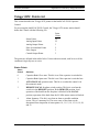
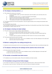
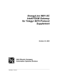
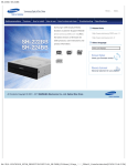
1
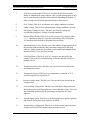
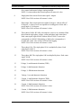
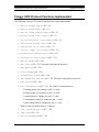
IntelliCAP PLUS® Supplement for Landis & Gyr Telegyr 8979 Protocol March 31, 2003 S&C Electric Company 1135 Atlantic Avenue Alameda, California USA 1023-563 / 3-31-03 IntelliCAP PLUS Capacitor Control Supplement for Landis & Gyr Telegyr 8979 Protocol S&C Electric Company Proprietary Information Proprietary Notice This document contains information which is proprietary to S&C Electric Company and is provided under the terms and conditions of a Purchase Order Terms and Conditions Agreement between S&C Electric Company and each of its customers. Disclosure of information contained in this document to third parties without prior written permission from S&C Electric Company is strictly forbidden. Information in this document is subject to change without notice and does not represent a commitment on the part of the vendor. Copyright 2003 S&C Electric Company All Rights Reserved. Printed in the USA. EnergyLine, the EnergyLine logo, and IntelliCAP PLUS are registered trademarks of S&C Electric Company. Hayes is a trademark of Hayes Microcomputer Products, Inc. UtiliNet is a registered trademark of SchlumbergerSema Inc. All other trademarks are the property of their respective holders. S&C Electric Company, 1135 Atlantic Avenue, Alameda, CA 94501, USA Tel (773) 338-1000 2 Telegyr 8979 Supplement 1023-563 / 3-31-03 S&C Electric Company Proprietary Information IntelliCAP PLUS Capacitor Control Supplement for Landis & Gyr Telegyr 8979 Protocol Contents Introduction_____________________________________________________________5 Applicable Software ____________________________________________________5 Manual Conventions ____________________________________________________5 Cautions______________________________________________________________5 Telegyr 8979 Setup Screens ________________________________________________6 View the First SETUP: Communications Screen ______________________________6 View the Second SETUP: Communications Screen ____________________________8 Telegyr 8979 Communications Troubleshooting Screen _________________________11 Telegyr 8979 Points List _________________________________________________13 Status Points _________________________________________________________13 Analog Input Points____________________________________________________16 Pulse Accumulator Points _______________________________________________18 Control Points ________________________________________________________19 Telegyr 8979 Protocol Functions Implemented ________________________________20 1023-563 / 3-31-03 Telegyr 8979 Supplement 3 IntelliCAP PLUS Capacitor Control Supplement for Landis & Gyr Telegyr 8979 Protocol S&C Electric Company Proprietary Information Notes: 4 Telegyr 8979 Supplement 1023-563 / 3-31-03 S&C Electric Company Proprietary Information IntelliCAP PLUS Capacitor Control Supplement for Landis & Gyr Telegyr 8979 Protocol Introduction This document describes the Landis & Gyr Telegyr 8979 implementation for the S&C IntelliCAP PLUS Capacitor Control For more information about the setup and operation of the IntelliCAP PLUS, see the User’s Manual. Applicable Software This document was prepared for use with standard software version PCSL114S and VAR software version PCVL114S. For questions regarding the applicability of information in this chapter to future software releases, please contact S&C Electric Company. Manual Conventions The following conventions are used in this chapter: BOLD UPPER CASE Labels on faceplates, assemblies, and switch positions. Italic Names of books, manuals, manual sections, and software screens. “Quotes” Names of fields on software screens. <Brackets> Names of computer keyboard keys. Courier Characters to be typed at the prompt and commands issued from the SCADA master station. Cautions All Cautions are clearly marked with the notation ! CAUTION !. Please read all cautions carefully before attempting to install or operate this equipment. 1023-563 / 3-31-03 Telegyr 8979 Supplement 5 IntelliCAP PLUS Capacitor Control Supplement for Landis & Gyr Telegyr 8979 Protocol S&C Electric Company Proprietary Information Telegyr 8979 Setup Screens This section describes the screens that are different for Switch Operators using Telegyr 8979 protocol. View the First SETUP: Communications Screen To display the first SETUP: Communications screen (Figure 1), click the Communications button at the SETUP MENU screen. Figure 1 First SETUP: Communications Screen This screen contains setpoints related to SCADA communications. The screen includes the following fields: Communications RTU Address If this Control will be accessed via SCADA communications, enter the network address for this installation. ! CAUTION ! If you move an already-configured control to a new location, be sure to enter the NEW address into the control. (If you leave the old address in the control, it may respond to instructions meant for a different control location.) 6 Telegyr 8979 Supplement 1023-563 / 3-31-03 S&C Electric Company Proprietary Information IntelliCAP PLUS Capacitor Control Supplement for Landis & Gyr Telegyr 8979 Protocol SCADA Communication Baud Rate If this control is part of a SCADA system, set this value to the baud rate between the control and the directly-connected device (radio, modem, etc.). If this setpoint does not match the baud rate for the device, communications will not operate. Transmitter Keying Delay Time This is the amount of time (in milliseconds) that must elapse from the moment the transmitter is turned on until the data transmission begins. You can usually leave this at the factory default value. Transmitter Turn-Off Delay Time This is the amount of time (in milliseconds) that the transmitter should remain on after the second-to-last character transmission has begun. You can usually leave this at the factory default value. Output Point Select Timeout This is the timeout duration of the Select function on control points. If the timeout duration is too short between the Select and the Operate functions during a Select-Before-Operate sequence, the Switch Operator disables the point. Allow RTU Memory Write Operations For security reasons, table writes (FC = 48, Table Writes) are by default disabled in this control. This feature is implemented for diagnostic purposes. Use care when enabling this feature, and disable it when you are done to prevent inadvertent changes to the control parameters. 1023-563 / 3-31-03 Telegyr 8979 Supplement 7 IntelliCAP PLUS Capacitor Control Supplement for Landis & Gyr Telegyr 8979 Protocol S&C Electric Company Proprietary Information View the Second SETUP: Communications Screen To display the second SETUP: Communications screen (Figure 1), click the PgDn button at the first SETUP: Communications screen. Figure 2 Second SETUP: Communications Screen This screen includes the following fields: Unsolicited Call Home Feature When the Call Home feature is enabled (if applicable), the Control initiates a call to the master station in response to a change in any status point. The Control uses the setpoints on this screen to determine when to call and how often to call. The Control attempts calls to the master until it makes a successful connection and the master has polled for the indication change report. NOTE: Before enabling the Call Home feature, be sure the Control is properly equipped with a land-line or cellular phone modem. Call Delay After First Event This is the amount of time that the Control waits after the first indication change event before initiating a call. This delay prevents the Control from making numerous consecutive calls for related events. Enter a time long enough for a related sequence of events to be completed but short enough for you to receive a timely notification. Call Retry After Busy or No Answer This is the amount of time that the Control waits after receiving a busy or no answer indication from the modem before attempting another call. Call Retry After Call Failure This is the amount of time that the Control waits after receiving an error indication from the modem before attempting another call. You can set this value to a longer time to reduce the number of call attempts when a problem exists in the telephone system or at the master station. 8 Telegyr 8979 Supplement 1023-563 / 3-31-03 S&C Electric Company Proprietary Information IntelliCAP PLUS Capacitor Control Supplement for Landis & Gyr Telegyr 8979 Protocol Number of Calls Per Phone Number This is the number of call attempts that the Control makes to each phone number in the “Phone Number” list before moving to the next number. Time to Wait for Connect This is the amount of time (in seconds) that the Control waits for the modem to report a “Connect.” If it does not connect to the master station’s modem within this period, the Control considers the attempt failed. When setting this value, be sure to take into account dialing commands, ring time, and modem connection time. Time to Wait for Master Poll This is the amount of time that the Control waits for the master station to make an indication change poll after a connection has been made with the master station’s modem. If a poll is not requested within this time, the Control hangs up the connection and schedules another call attempt. Modem This setpoint lists factory-supported modems. While other modems may be compatible, default setup strings are provided for the listed modems (see “Setup String” below). Setup String This is the string of commands sent to initialize the modem before communication begins. In general, you can leave the setup string at the factory default value for each factory-supported modem (see “Modem” above). You can also enter a new value, if needed. To return to the default setup string, change the “Modem” parameter back to the desired modem. Reinitialize Modem If you change the “Setup String” setpoint, set this field to “Init” to reinitialize the modem. You must also initialize the modem the first time you enable the Call Home feature. Pulse or Tone Dialing This setpoint selects pulse or tone dialing at the Control’s modem. Set it to the value required by your telephone service provider. Phone Number This is a list of up to 10 phone numbers that the Control dials when attempting to contact the master station. You may enter any number, along with any Hayescompatible dialing commands. Examples of dialing commands are “,” to pause 2 1023-563 / 3-31-03 Telegyr 8979 Supplement 9 IntelliCAP PLUS Capacitor Control Supplement for Landis & Gyr Telegyr 8979 Protocol S&C Electric Company Proprietary Information seconds during dialing, “@” to wait for silence, and “W” to wait for a second dial tone. You can add or delete numbers as needed. The numbers do not need to be consecutive in the list. Numbers are dialed consecutively starting at the first number in the list. If the first number is not reachable after the configured number of tries (see “Number of Calls per Phone Number”), the Control moves to the next number in the list. When it reaches the end of the list, it begins again with the first phone number. 10 Telegyr 8979 Supplement 1023-563 / 3-31-03 S&C Electric Company Proprietary Information IntelliCAP PLUS Capacitor Control Supplement for Landis & Gyr Telegyr 8979 Protocol Telegyr 8979 Communications Troubleshooting Screen The TROUBLESHOOTING: Communications screen (Figure 3) shows a chronological listing of Telegyr 8979 communications problems. To display the TROUBLESHOOTING: Communications screen, click the Comm Problems button on the TROUBLESHOOTING MENU screen. Figure 3 TROUBLESHOOTING: Communications Screen The log can hold 10 entries. Once the log is full, each new event over-writes the oldest event in the log. To find the most recent event, look for the message with a timestamp that is older than the time for the message above it. This screen includes the following fields: Date/Time...MSec This is the time (to the nearest 6.25 milliseconds) when the event occurred. Reason for Communications Failure This is the reason that communications failed. One of the following messages appears: • “Packet CRC Error” • “Internal: Bad UART interrupt” • “First character of packet not $FF” • “Packet length illegal” • “Packet contains bad characters/framing” • “Timeout on control select operation” • “Modem receive buffer overrun” • “Phone number list is empty” 1023-563 / 3-31-03 Telegyr 8979 Supplement 11 IntelliCAP PLUS Capacitor Control Supplement for Landis & Gyr Telegyr 8979 Protocol 12 • “Modem reset failed” • “Setup string rejected” • “Dialing the phone failed” • “Connect to master failed” • “Poll was not received from master” • “Hang up failed” Telegyr 8979 Supplement S&C Electric Company Proprietary Information 1023-563 / 3-31-03 S&C Electric Company Proprietary Information IntelliCAP PLUS Capacitor Control Supplement for Landis & Gyr Telegyr 8979 Protocol Telegyr 8979 Points List This section describes the Telegyr 8979 points for the IntelliCAP PLUS Capacitor Control. For accessing the IntelliCAP PLUS Control, the Telegyr 8979 master station should define the Control with the following I/O: Point Count Status Points Analog Input Points Analog Output Points Pulse Accumulator Points Pulse Output Control Output Points 24 25 3 2 1 3 The points are defined in the tables below. Unless otherwise noted, each bit is set if the condition is logically true or active. Status Points Status Point # Definition 0 Capacitor Bank Close state. This bit is set if the capacitor is switched in. 1 Capacitor Bank Open state. This bit is set if the capacitor is switched out. 2 AUTO/MANUAL operation state. This bit is set when the control is in the automatic mode. 3 REMOTE/LOCAL faceplate switch position. This bit is set when the switch is in the REMOTE position. In the REMOTE position, local operation of the bank from the faceplate is blocked. In the LOCAL position, operation of the bank from the SCADA master station is blocked. 4 Alarm Summary. This bit is set when an alarm or trouble condition occurs. This is a summary bit. The exact cause of the alarm can be determined from inspection of status points: 10, 11, 12, 14, 15, 18, 19, 20, and 23. 1023-563 / 3-31-03 Telegyr 8979 Supplement 13 IntelliCAP PLUS Capacitor Control Supplement for Landis & Gyr Telegyr 8979 Protocol 14 S&C Electric Company Proprietary Information 5 SCADA Override enabled. This bit is set when the SCADA Override feature is enabled in the setup software. This override strategy may or may not be controlling the bank state when enabled, depending on the state of other overrides and SCADA commands that have been issued. 6 Over Voltage. This bit is set when an over voltage condition is present. 7 Under Voltage. This bit is set when an under voltage condition is present. 8 Emergency Voltage Override. This bit is set when the voltage has exceeded the Emergency Voltage Override boundaries. 9 Reclose Delay Blocked. This bit is set for a period of five minutes after a Trip operation to allow the capacitors to discharge fully. During this five minute period, the bank is prevented from reclosing. 10 Maximum Daily Cycles. This bit is set if the number of open operations of the capacitor bank reaches the daily maximum configured in the setup software. Further automatic operations are prevented until midnight if the maximum Daily Cycles has been reached. 11 Load Fuse Blown. This bit is set if AC voltage is not detected by the control. If the control is communicating, it indicates that the load fuse is probably blown. 12 Temperature sensor error. This bit is set if an error has been detected in the temperature sensor. 13 Temperature System. If this bit is set, temperature is reported in °F, if cleared temperature is reported in °C. 14 Incorrect voltage range. This bit is set if an error has been detected in the voltage sensor. 15 Low switching voltage delta. This bit is set if the delta voltage measured during the present switching operation is lower than the average of the last four switching operations by the percentage configured in the setup software. 16 Neutral Sensor option. This bit is set if the neutral sensor option is present, and cleared if no neutral sensor option is installed. 17 Neutral Sensor configuration. This bit is set if the neutral sensor measures voltage, and cleared if the neutral sensor measures current. Telegyr 8979 Supplement 1023-563 / 3-31-03 S&C Electric Company Proprietary Information IntelliCAP PLUS Capacitor Control Supplement for Landis & Gyr Telegyr 8979 Protocol NOTE: Versions without the Neutral option will return a 0 value. 18 Neutral Sensor. This bit is set when the neutral current or voltage remains above the “Neutral Alarm Level” for a period of time specified by the “Neutral Change Time Threshold.” If the “Corrective Action” and “Neutral Retry” features were enabled in setup software, and this bit is set, the retry operation was unsuccessful. This alarm prevents further operation of the capacitor bank by any automatic means. To reset, issue Pulse Output point 0, “Reset Neutral Lockout”. 19 Continuous Neutral Sensor. This bit is set when the neutral current or voltage remains above the “Neutral Alarm Level” for a period of time specified by the neutral “ Change Time Threshold.” It is reset if the neutral current or voltage falls below the “Neutral Alarm Level.” NOTE: Versions without the Neutral option will return a 0 value.. 20 Zero Neutral Sensor. This is a user selectable option, if enabled in the setup software, this bit is set if the neutral sensor is detecting zero neutral current or voltage indicating a possible problem with the neutral sensor or its cabling. This only applies when the bank is switched in. NOTE: Versions without the Neutral option will return a 0 value. 21 VAR Option. This bit is set if the VAR option is present, and cleared if no VAR option has been installed. 22 Reverse current. This bit is set if the Control has detected that the direction of current flow is reversed from the normal direction. This should only occur during emergency switching operations. NOTE: Non-VAR versions will return a 0 value. 23 Low switching VAR delta. This bit is set if the delta VAR measured during the present switching operation is lower than the average of the last four switching operations by the percentage configured in the setup software. NOTE: Non-VAR versions will return a 0 value. 1023-563 / 3-31-03 Telegyr 8979 Supplement 15 IntelliCAP PLUS Capacitor Control Supplement for Landis & Gyr Telegyr 8979 Protocol S&C Electric Company Proprietary Information Analog Input Points Analog Input Point # Definition 0 90% voltage reference standard. This is provided for the benefit of the protocol implementation to conform to the RTU standard. It is loaded as a constant. 1 0% voltage reference standard. This is provided for the benefit of the protocol implementation to conform to the RTU standard. It is loaded as a constant with the value zero. 2 Control strategy. This is the presently configured control strategy in use. The possible values are: 0 Temperature 1 Timeclock 2 Voltage Only 3 Time-Biased Voltage 4 Time-Biased Temperature 5 Auto Off-Line Mode 6 Auto On-Line Mode 7 Current 8 VAR 9 Reverse Current Voltage Only 10 Temperature Sensor Error, Voltage Only. 11 SCADA Override 12 Timeclock with Temperature Override 13 Current with Temperature Override 14 VAR with Temperature Override NOTE: Values 7, 8, 9, 13 and 14 do not apply to non-VAR versions. 16 3 The most recent temperature reading. This value is in units of °F or °C (with a 50 degree offset) as selected in the IntelliLINK Set-up Software. 4 Most recent (secondary) voltage measurement. Each count equals 0.1 VAC RMS. 5 Primary Line Voltage. Each count equals 10 VAC RMS. NOTE: Non-VAR versions will return a 0 value. 6 The time remaining in SCADA Override mode. If in timed mode, returns the number of minutes remaining, if in latched mode, always returns 4095. 7 Neutral current or Neutral voltage. Each count equals 1 ampere for a control with neutral current sensing installed or each count equals 1 Volt Telegyr 8979 Supplement 1023-563 / 3-31-03 S&C Electric Company Proprietary Information IntelliCAP PLUS Capacitor Control Supplement for Landis & Gyr Telegyr 8979 Protocol for a control with neutral voltage sensing installed. NOTE: Versions without the Neutral option will return a 0 value. 8 Single-phase line current. Each count equals 1 ampere. NOTE: Non-VAR versions will return a 0 value. 9 Phase angle. Each count equals one eighth of a degree with an offset of 90 degrees. A value of zero corresponds to a leading power factor and a power angle of –90 degrees. NOTE: Non-VAR versions will return a 0 value. 10 Three-phase kVARs. KVARs (volt-amperes, reactive) are calculated from the measured single phase voltage, current and phase angle times three. Each count equals eight kVARs with an offset of 2048. A zero value corresponds to 16384 kVARs leading, a 2048 value corresponds to 0 kVARs and a 4095 value will be 16384 kVARs lagging. NOTE: Non-VAR versions will return a 0 value. 11 Three-phase kVA. The single-phase kVA is multiplied by three. Each count equals 10 kVA. NOTE: Non-VAR versions will return a 0 value. 12 Three-phase kW. The single-phase kW is multiplied by three. Each count equals 10 kW. NOTE: Non-VAR versions will return a 0 value. 13 Voltage, % total harmonic distortion (THD). 14 Voltage, % third harmonic distortion. 15 Voltage, % fifth harmonic distortion. 16 Voltage, % seventh harmonic distortion. 17 Current, % total harmonic distortion (THD). NOTE: Non-VAR versions will return a 0 value. 18 Current, % third harmonic distortion. NOTE: Non-VAR versions will return a 0 value. 19 Current, % fifth harmonic distortion. NOTE: Non-VAR versions will return a 0 value. 1023-563 / 3-31-03 Telegyr 8979 Supplement 17 IntelliCAP PLUS Capacitor Control Supplement for Landis & Gyr Telegyr 8979 Protocol S&C Electric Company Proprietary Information 20 Current, % seventh harmonic distortion. NOTE: Non-VAR versions will return a 0 value. 21 Neutral, % total harmonic distortion (THD). NOTE: Versions without the Neutral option will return a 0 value. Neutral, % third harmonic distortion. NOTE: Versions without the Neutral option will return a 0 value. 22 23 Neutral, % fifth harmonic distortion. NOTE: Versions without the Neutral option will return a 0 value. 24 Neutral, % seventh harmonic distortion. NOTE: Versions without the Neutral option will return a 0 value. Analog Output Points Analog Output Point # Definition 0 Low voltage override for the SCADA Override mode. The values are entered at 0.1 Volt increments, e.g. 130.0 Volts = 1300. 1 High voltage override for the SCADA Override mode. The values are entered at 0.1 Volt increments, e.g. 130.0 Volts = 1300. 2 SCADA Override Timer (in timer byte format). Time values supported are: 5, 15, or 30 minutes and 1–4 hours. 255 (decimal) is the latched mode. (Decimal values are: 133, 143, 158, and 193–196.) Pulse Accumulator Points Pulse Accumulator Point # Definition 18 0 Total cycles since installation. This is the number of switch operations since the installation of the Control. The counter is incremented when the bank is switched out. This is a 16-bit counter and will overflow back to zero at 65,535. 1 Total cycles this year. This is the number of switch operations during this calendar year. The counter is incremented when the bank is switched out. This is a 16-bit counter and will overflow back to zero at 65,535. Telegyr 8979 Supplement 1023-563 / 3-31-03 S&C Electric Company Proprietary Information IntelliCAP PLUS Capacitor Control Supplement for Landis & Gyr Telegyr 8979 Protocol Control Points(SBO) Control Point # Definition NOTE: For the Control-Select-Trip and Close commands, the timer value in the function definition must be non-zero. 0 REMOTE manual override close/open command. A ControlSelect-Close command switches the bank into the circuit. A Control-Select-Trip command switches the bank out of the circuit. NOTE: Use control point 1 to enable manual operation before issuing trip or close commands. If these commands are issued with SCADA Override enabled, SCADA Override will become active for the SCADA Override timer duration. The command will return an exception error if the hardware faceplate switch is not in the REMOTE position. 1 Enable or disable “Automatic” operation. A Control-Select-Close command enables automatic operation. A Control-Select-Trip enables manual operation. 2 Enable or disable SCADA Override mode. A Control-SelectClose command enables SCADA Override. A Control-SelectTrip disables SCADA Override. . When enabled, issuing a close or trip command to control point “0” will start the SCADA Override mode. Pulse Output Points Control Point # Definition 0 Reset Neutral Lockout. Raise(value >= 128) = Reset. 1023-563 / 3-31-03 Telegyr 8979 Supplement 19 IntelliCAP PLUS Capacitor Control Supplement for Landis & Gyr Telegyr 8979 Protocol S&C Electric Company Proprietary Information Telegyr 8979 Protocol Functions Implemented The following Telegyr 8979 protocol functions have been implemented: • Analog Change Report (FC = 0) • Analog Force Report (FC = 1) • Analog Group Change Report (FC = 2) • Analog Group Force Report (FC = 3) • Analog Reference Force Report (FC = 5) • Indication Change Report (FC = 6) • Indication Force Report (FC = 7) • Digital Input Force Report (FC = 11) • Accumulator Change Report (FC = 12) • Accumulator Force Report (FC = 13) • Analog Output (FC = 20) • SBO Select (FC = 21). The timer count must be non-zero. • SBO Operate (FC = 22) • Pulse Output (FC = 25) • Accumulator Freeze (FC = 24) • SBO Immediate Execute (FC = 28). The timer count must be non-zero. • Restart RTU (FC = 30) • RTU Configuration (FC = 31). The Control’s configuration is: 25 analog points @ 8 points per card = 4 cards 24 status points @ 16 points per card = 2 cards 3 control points @ 8 points per card = 1 cards 2 accumulator points @ 8 points per card = 1 card 1 pulse output point @ 8 points per card = 1 card With 16 cards per chassis, there is 1 chassis. 20 • Time Synchronization (FC = 32) • Time Bias (FC = 33) • Analog Deadbands (FC = 34) Telegyr 8979 Supplement 1023-563 / 3-31-03 S&C Electric Company Proprietary Information IntelliCAP PLUS Capacitor Control Supplement for Landis & Gyr Telegyr 8979 Protocol • Analog Group Define (FC = 35) • Continue Request (FC = 37) • Repeat Last Message (FC = 38) • Firmware Configuration (FC = 39) • Table Read (FC = 47) • Table Write (FC = 48). Before a Table Write command is accepted, a value of 15 (hex) must have been written to location 1006 (hex), or writes must have been enabled on the second SETUP: Communications screen. • Exception Report (FC = 63) The following Telegyr 8979 protocol functions and commands are not supported (an Invalid Function Code exception report is generated): • SOE Change Report (FC = 8) • SOE Force Report (FC = 9) • SOE Log Change Report (FC = 14) • Digital Output (FC = 23) • Pulse Train Output (FC = 26) • Accumulator Preset (FC = 36) 1023-563 / 3-31-03 Telegyr 8979 Supplement 21 IntelliCAP PLUS Capacitor Control Supplement for Landis & Gyr Telegyr 8979 Protocol S&C Electric Company Proprietary Information Default Settings of RTU Internal Parameters When the Control is first powered-up, it performs a “cold start”, during which the following settings are made: 22 • All analogs are placed in group 0. • Analog deadbands are set to “255”. • Analog and indication change flags are cleared • A cold start can also be initiated by the master station. Telegyr 8979 Supplement 1023-563 / 3-31-03