1
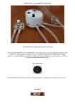
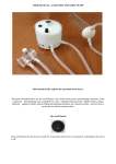
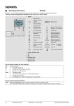
USER MANUAL
This manual will briefly explain the simple operation of the device. The points illustrated below are:
the on/off button, the current switch, power and charging connectors, air connector, regulation
intensity knob, controlled loss valve, display, setting vacuum values.
The on/off button
The on/off button turn the device on and off. In I position the device is in operation, in O position the
device is off.
The switch
As in the figure above: selects the type of power supply (only for the dual power supplymodel A/C
batteries), with AC batteries or power supply. The switch positioned on the left supplies batteries
device. The switch positioned on the right supplies the device with AC transformer. To use the
battery, keep the selector positioned on the left. To use AC power, keep the switch positioned to the
right. In order to recharge the battery keep the switch positioned to the left. If while using the batterypowered device the switch is moved to the right, the device will lose power and stop.
The left connector is only used to recharge the battery while the device is not in use. The right
connector is for AC power supply and should only be used to supply the device while it is in use.
Air quick-connector
The air quick-connector, as above connects the vacuum tube to the cylinder. It is equipped with a
quick release. In order to connect the small tube, push gently and operate the quick release. To
disconnect, press the metal lever and gently pull the vacuum tube.
Intensity control knob
The intensity control knob, above is a current regulator that regulates the strength, the speed and
the noise level of the device. It must be used gently. The intensity increases by turning it clockwise.
The intensity decreases by turning it anti-clockwise. If you turn the knob completely anti-clockwise
you remove the power to the device and it stops. This is normal.
The knob regulates the strength and the speed of vacuum increase, and also the noise (though
moderate) that the device emits. Applying more power to the vacuum pump draws out air more
quickly from the vacuum circuit (clockwise). Applying less power to the vacuum pump draws out air
more slowly (anti-clockwise).
Controlled leak valve
The Controlled leak valve generates a minimum leak in the vacuum circuit allowing a slow vacuum
decrease. It must be used gently. Do not tighten firmly, as it could cause damage and is not required.
Using two fingers is sufficient to completely stop the leak, close the valve completely and also stop the
loss of vacuum.
By turning it clockwise the quantity of controlled leak decreases.
By turning it anti-clockwise the quantity of controlled leak increases.
To increase or decrease the leak and air quantity inside the vacuum circuit, increase or decrease
respectively the time to decrease the vacuum until the preset value is reached.
If you want slower cycles, the controlled leak valve needs to be turned clockwise to slow the leak rate.
This will extend the time to reach the minimum set vacuum. If you want faster cycles, the controlled
leak valve should be turned a little anti-clockwise. This increases the leak rate and the vacuum will
now require less time to reach the minimum preset value.
Initial Operation
When you first operate the pump the leak valve should be fully closed (turn gently fully clockwise).
When you reach the maximum vacuum setting open a little (a few millimetres) and by experimenting
you will be able to achieve your desired rate of vacuum reduction.
The display
From the display you can display the vacuum value inside the circuit.
When the vacuum pump is active the numbers will be displayed in red. When the pump is not active
the numbers will displayed in green. When the device starts, the display flashes for some seconds
(about 2 seconds) and it starts at the values that have been set previously. The display shows the
vacuum inside the vacuum circuit in inches of Hg (they can also be displayed in Bar, Psi etc.) Without
having closed the vacuum circuit, by connecting the small tube the display will show - 0,1/- 0,2, that is
normal since there is no vacuum.
Led indicator battery charge level.
When it is green, the charge is about 100%, when is
Yellow indicates a charge from 80% to 30%. When is red indicates
a charge under 30% and then you have to recharge before the next use
of the device.
Vacuum regulation buttons
The device is equipped with three buttons from which you can regulate the minimum and maximum
vacuum which can be set in two different ways.
Setting minimum vacuum (N_I)
1) To set minimum vacuum turn on the device by turning the power switch on (I position). The
display will show – 0,1/-0,2,
2) now press the central button
once. You will display the flashing writing
N_I present
value.
3) Press the button on the right
to decrease or press the button on the left
to
increase
4) press the central button once more and you have finished setting minimum vacuum.
For example, use the side left and right buttons to set –3,7” Hg. So the value -3.7” Hg that you have
just set means that: when vacuum arrives to -3.7 the device starts and leads the vacuum to the
maximum preset value, the vacuum inside the vacuum circuit will not decrease under -3,7”.
To set the maximum vacuum value vacuum that the device will reach you set a number (H_I). H_I
represents the increase in vacuum from the minimum set vacuum ( N_I) (ie Maximum set vacuum =
N_I + H_I).
Setting H_I
1. Turn on the device by pressing I, the display will show – 0.1/ -0.2, hold down the central
button
for at least 3 seconds, the display will show the writing F 0,
2. press the left button
once, the display will show the writing F 1.
3. Now press the central button four times until the display shows the writing H_I. You increase
with the button on the left and decrease with that on the right.
4. then press again the central button for at least 3 seconds, the display will show the writing –
0,1/-0,2, and you have now set the maximum value.
Examples
If you want to make:
.
cycles at a minimum vacuum of -4.0 and a maximum vacuum of -9.0: set the minimum value
(N_I) at -4.0 and set H_I value at 5.0.
.
Cycles at a minimum vacuum of -3.3 and maximum vacuum of 10.2: set N_I to – 3.3, set H_I
to 6.9.
.
cycles at a minimum vacuum of -4,5, maximum vacuum of - 8,7: set N_I -4,5 and H_I to 4,2.
.
cycles at a minimum vacuum - 5,5 maximum vacuum - 11,0: set N_I to - 5,5 and H_I to 5,5.
Note: If you have -4.0 as minimum value and -8.0 as maximum value, when you modify only the value
N_I that is – 4.0 and you bring it to – 5.0, for example, you will obviously increase the maximum value
H_I too, so it will automatically become - 9.0, so you will have -5.0 as minimum value and -9.0 as
maximum value. .
It might seem complicated but in reality it is simple because if correctly used usually you will normally
only change the maximum value, while you will almost always have the same minimum value (ie you
will normally only modify the H_I value).
You are advised to adjust minimum and maximum values by following this handbook exclusively
without relying on any other menu option, but if you "unconfigure" the menu in error with the buttons
under the display, contact [email protected] , we will help you with reprogramming.
Lithium-ion battery
The dual power supply version of the device includes a lithium-ion battery, a very powerful and safe
new generation battery that can supply the device for some hours, with a range of at least two full
hours; the battery charging must be done exclusively when the device is not in use. The battery must
be charged when necessary, do not charge the battery continually if it is not out of power for about
70/80 % or there will be the risk of nullifying its duration.
Static pumping
The device has been designed for dynamic pumping. It has a natural slow vacuum leak that is
amplified and regulated by the controlled loss valve. If you wish to use the device for static pumping
you have to remember that is does not maintain a constant vacuum but will always tend to slowly lose
vacuum.
Checking pump settings
1. Turn on the device.
2. Turn the black knob fully counterclockwise.
3. Press the central (S) button for 3-4 seconds and arrive in F_0.
4. Press center (S) button one time and ensure the settings for uni is inH, if not press up or down arrows to change the value.
5. Press center (S) button one time arrive at F_0.
6. Press left (up) button one time and arrive at F_1
7. Press center (S) button one time and ensure the setting for oUI is HYS, if not press up or down arrows to change the value.
8. Press center (S) button one time and ensure the setting for lot is I_n, if not press up or down arrows to change the value.
9. Press center (S) button one time and ensure the setting for n_I is -3 (your minimum vacuum), if not press up or down arrows
to change the value.
10. Press center (S) button one time and ensure the setting for H_1 is 7 (your maximum vacuum), if not press up or down
arrows to change the value.
11. Press center (S) button one time and ensure the setting for Col is Sor, if not press up or down arrows to change the value.
12. Press center (S) button one time and arrive at F_1 and settings is complete.
13. Press and hold center (S) button for 3-4 seconds to arrive at vacuum display.
Ensure the display is red and the value is 0.0/0.1, and screw black knob clockwise to desired pumping
speed .