1
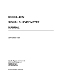
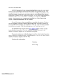
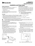
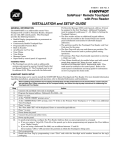
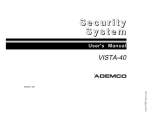
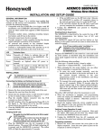
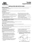
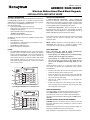
K0020V1 7/04 Rev. A
ADEMCO 5828/5828V
Wireless Bidirectional Fixed-Word Keypads
INSTALLATION AND SETUP GUIDE
GENERAL INFORMATION
Operation (See NOTE below)
The 5828 and 5828V are wireless, bidirectional, fixed-word,
nonaddressable keypads that are used in conjunction with
LYNX Series control panels or VISTA Series control panels
that are using a 6160RF Keypad transceiver.
Both keypads provide:
•
Four programmable special function keys
•
Wall-mount plate allowing easy removal of the keypad
and battery replacement
•
Optional Desktop mount /AC adapter kit,
(ADEMCO P/N 5828DM)
•
Battery powered with 3-AA batteries
1. Battery-Powered Operation:
When powered by
battery, the keypads activate when any key is pressed.
When the key is pressed, the keypad sends a status request
to the control. The keypad displays and/or annunciates the
present system status transmitted by the system.
In addition to the above features, the 5828V keypad provides
the following:
•
Memo/Message center
•
Voice Response – system status, zone information, and
alarms with zone information
•
Stored Message LED indication
•
Built-in microphone and speaker
NOTES:
•
The 5828/5828V cannot be used as a primary keypad to
program and/or test any security system. All systems
require a hard-wired keypad to do so. Once programmed
and tested, the 5828/5828V can be used to initiate all
other keypad functions in both the VISTA and LYNX
series systems. However, you must have at least one
hard-wired keypad permanently connected on VISTA
series control panels.
2. AC-Powered Operation: When powered by AC, the
keypad remains active at all times. Any change in system
status will cause the display to automatically turn on (if
blank) and display/annunciate the new status.
If AC power is lost, the keypad will revert to battery-powered
operation until AC power is restored and a new status
request is made.
NOTE: Whether the unit is powered by battery or AC, the
5828/5828V may take up to 5 seconds to display and/or
annunciate the new status after pressing the [✱] key.
WALL MOUNTING
Before mounting the 5828 & 5828V permanently,
determine a good RF location as follows:
•
If interfacing to a LYNX panel, try communicating
with the panel from different locations.
•
If interfacing to a VISTA panel, perform a Go/No
Go test from the panel. Refer to the Go/No Go test
mode in the Installation and Setup Guide for the
panel.
Avoid mounting locations on or near large metal objects,
since these can decrease the transmission range or block
transmissions.
A
3
OFF
2
4
MAX
5
TEST
6
BYPASS
7
INSTANT
8
CODE
9
CHIME
READY
0
ARMED
1
READY
C
AWAY
STAY
5828-00-001-V0
B
#
D
5828 Keypad with Front Cover Removed
•
Secure the mounting plate to the wall, using proper sized
hardware through the six mounting holes.
•
Route the wires from the optional power pack through
the wire guides on the back of the keypad and into the
hole in the back of the keypad.
•
Plug the AC adaptor connector into the keypad’s DC
input connector.
•
Position the keypad over the mounting plate and slide
down, engaging the four retaining clips on the plate with
the receptacles on the keypad.
DESKTOP MOUNTING
For full portability, the keypad may be placed in any convenient, RF-suitable location and operated in its batterypowered mode, or near an AC outlet to be powered by the
optional Power Pack/Desktop Mounting Kit, ADEMCO P/N
5828DM.
MIC
MESSAGE
A
ARMED
READY
C
D
1
OFF
2
AWAY
VOLUME
3
STAY
RECORD
4
MAX
5
TEST
6
BYPASS
7
INSTANT
8
CODE
9
CHIME
READY
0
STATUS
VOICE
BATTERY INSTALLATION OR REPLACEMENT
PLAY
#
FUNCTION
5828V-00-002-V0
B
5828V Keypad with Front Cover Removed
CAUTION: Remove the AC/DC power connector from the
keypad (if applicable), before attempting to install or replace
the batteries.
Separate the keypad from its mounting plate by sliding the
keypad up and away from the mounting plate.
Open the battery compartment door to expose the batteries.
Install or replace the 3-1.5 Volt AA batteries in the battery
compartment. When necessary, always replace all three
batteries at once to ensure normal operation of the keypad
over the anticipated battery lifetime. Make sure that battery
positive (+) and negative (–) terminals are properly oriented
with the battery spring clip connections. Refer to battery
placement graphic below.
3.
Press [3] (Exit Delay)
Press 0-9 in 15 second increments.
Example: If you press 3, exit delay
would be 3 times 15 seconds for a total
of 45 seconds.
NOTE: The Exit Delay programmed
here should match the Exit Delay
programmed in the control panel.
(0 = default)
Alternately
flashes “t3”
and value
selected.
Press [✱] to continue.
4.
(5828V
only)
AA BATTERY
Press [4] (Voice enable/disable).
Press (0) to disable.
Press (1) to enable.
(1 = default)
Alternately
flashes “t4”
and (0 or 1)
Press [✱] to continue.
AA BATTERY
5.
Press [5] (Wireless Protocol).
Press [1] for LYNX models
Press [2] for LYNXR, LYNXREN, or
VISTA
(2 = default)
6.
Press [6] (Function Key Select).
Press [0] for Panic Key
Press [1] for Single-button arming
NOTE: The programming here should
match the programming of the control
panel to simplify end user operation.
(1 = default.)
7.
Press [7] (Restore Defaults).
Press [1] to restore factory settings.
batt_case-001-V0
AA BATTERY
Alternately
flashes “t5”
and (1 or 2)
Press [✱] to continue.
Battery Compartment
Reattach the keypad to its mounting plate by aligning the
four mounting holes in the keypad case back with the four
mounting clips on the mounting plate. Lower the keypad
onto the clips.
Alternately
flashes “t6”
and (0 or 1)
Press [✱] to continue.
Anticipated battery life is 1.5 years.
Displays
“EE”
Press [✱].
Exit programming mode.
PROGRAMMING
Exiting Programming Mode
The following two items must be programmed into the
keypad by the installer.
•
•
You can exit programming mode by pressing the [✱] key
whenever the small 00 and (- -) are alternately displayed.
House ID Code (Step 1 in Installer Programming mode)*
Programming or Changing a User Code (Required if
using Quick Arm function on Lynx or VISTA)
System Type (Step 2 in Installer Programming mode)
Enter the program mode by pressing the [1] and [3] keys
simultaneously for five (5) seconds.
Enter user program mode by pressing the [7] and [9] keys at
the same time until the display flashes double dashes (- -).
Enter the desired 4-digit user code that matches a user code
programmed in the control panel. There will be no display
of the user code entered.
Press the [✱] key to place the 4-digit code in memory and
exit the user program mode.
The DISPLAY alternately flashes small 00 and two dashes
(--).
SPECIAL FUNCTION KEYS
*The same House ID Code must also be programmed in the
control panel. Programming a different House ID will
disable communication.
Installer Programming
As shown in the figures on page 1, each keypad contains four
Special Function keys (A, B, C, D) that may be programmed
to execute the commands shown below.
NOTES:
•
Entering a value other than one specified in the
following steps may cause unpredictable results.
•
If the unit times out before you have pressed the star
(✴) key to save a programmed value, you will need to reenter the Programming mode and reprogram the option.
STEP
1.
ACTION
DISPLAY
Press [1] (House ID Code)
(10 = default)
Enter the two-digit house code (01-31)
Alternately
flashes “t1”
and the 2digit house
code.
Alternately
flashes “t2”
and 2
Press [✱] to continue.
2.
Press [2] (System Type).
Press (1) for VISTA or (2) for LYNX
(2 = default)
NOTE: The Function Key Select setting in Step 6 of the
INSTALLER PROGRAMMING procedure above, determines
the operation of the Special Function keys A, B, C, and D as
follows:
If you select “0”
Function Key
A
B
C
D
Message Sent
to Control
Function
[1] + [✱]
(Alarm zone 95)
[✱] + [#]
(Alarm zone 99)
[3] + [#]
(Alarm zone 96)
(Not used for panic alarms)
NOTE: Do NOT use the 5828V for silent panic operation
because the keypad itself is not silent.
Press [✱] to continue.
-2-
If you select “1” (normally used on LYNX controls)
Function Key
A
B
C
D
the control panel, which can only be retrieved using the
LYNX keypad.
Function
“Off”
Arms “AWAY”
Arms “STAY”
(For future use)
To delete a message: Record a new message to override the
old one.
Muting system status announcements has NO affect on
the message recording or playback capability.
MEMO/MESSAGE CENTER
The MESSAGE CENTER table that follows explains what
can be done using the message center of the 5828V, and the
keys to press to enable each function.
If volume is adjusted (3↑ or 6↓) when a message is played
back, and the user still wants system status announcements
to be muted, the user must again mute system status
announcements (# + 2 + 1 for LYNX or # + 0 + 2 + 1 for
VISTA).
NOTE: Allow any status annunciation to complete before
starting to record a message.
POWER CONNECTIONS
In a typical configuration, the 5828 and 5828V keypads are
powered by 3-AA batteries.
MESSAGE CENTER (LYNX)
TO:
Record a message:
Stop recording before end of 20 seconds:
Playback a message:
Adjust message playback volume:
Mute keypad status announcements:
Restore keypad status announcements:
PRESS:
#+1
1
#+3
# + 2 + 3↑ or 6↓
#+2+1
# + 2 + 3↑ or 6↓
The 5828 and 5828V keypads can also be powered from an
optional Power Pack/Desktop Mounting Kit. See detailed
specifications for the Kit below.
It is recommended that three AA batteries be installed as a
backup power source when using the Power Pack/Desktop
Mounting Kit.
5828/5828V SPECIFICATIONS:
MESSAGE CENTER (VISTA)
TO:
Record a message:
Stop recording before end of 20 seconds:
Playback a message:
Adjust message playback volume:
Mute keypad status announcements:
Restore keypad status announcements:
PRESS:
#+0+1
1
#+0+3
# + 0 + 2 + 3↑ or 6↓
#+0+2+1
# + 0 + 2 + 3↑ or 6↓
Physical:
Frequency of
Operation:
Batteries:
Power Pack/
Desktop Mounting Kit
(optional):
LCD Display:
Sounder:
New message indication: When the keypad is activated in
battery-powered mode and a message had been recorded, the
red message LED will blink until the keypad turns off or the
message is played back.
6-1/4” W x 4-3/4” H x 1-3/8” D (159mm
x 121mm x 35mm)
345 MHz
3-1.5 Volt, AA, Alkaline
110VAC input, 5.0 Volt Regulated DC
output, 220mA, ADEMCO P/N 5828DM
Fixed-Word Liquid Crystal
Speaker
SUPERVISION
When powered by AC, if a message had been recorded, the
red message LED will blink continuously until the stored
message has been played back.
A 5828/5828V keypad low battery condition will be
displayed as “BAT” on Zone “00” until the battery drops
below a minimum level and the display goes blank.
NOTE: If the word “MESSAGE” is annunciated on the
5828V keypad, it means that there is a message waiting at
NOTE: When programming zone descriptors in the panel, you must select from words supported by both the 5828V
(shown in Table 1 below) and words supported by the control panel. If you use any other words, the 5828V will not
annunciate them. Refer to the control panel’s Installation and Setup Guide for specific instructions on programming
zone descriptors.
TABLE 1. ZONE DESCRIPTORS
ALARM
DEN
FOUR*
MEDICAL*
ATTIC
DETECTOR
FRONT
MESSAGE**
AWAY
DINING
GARAGE
MOTION
BABY
DOOR
GUN
NINE*
BACK
EIGHT*
INSIDE
NOT
BASEMENT
EMERGENCY
INSTANT
NOW
BATHROOM
EXIT
KITCHEN
OFFICE
BEDROOM
FAULT
LAUNDRY
ONE*
BYPASSED
FIRE
LIBRARY
OPEN*
CHECK
FIRST
LIVING
PANIC*
CHIME
FIVE*
MAIN
PATIO
CLOSED*
FLOOR
MASTER
POLICE*
* These Descriptors are available with VISTA Series control panels ONLY
** This Descriptor is available with Lynx Series control panels ONLY
-3-
POOL
READY
ROOM
SECOND
SEVEN*
SHED
SHOP
SIDE
SIX*
SLIDING
SMOKE
STAY
STORAGE
SYSTEM
TEN*
THIRD
THREE*
TWO*
UPSTAIRS
UTILITY
WINDOW
YARD
ZERO*
ZONE
FCC STATEMENT
FCC ID: CFS8DL5828
CANADA: 1748A-5828
This device complies with Part 15 of the FCC rules. Operation is subject to the following two conditions: (1) This device
may not cause harmful interference, and (2) This device must accept any interference received, including interference that
may cause undesired operation.
FEDERAL COMMUNICATIONS COMMISSION (FCC) Part 15 STATEMENT
This equipment has been tested to FCC requirements and has been found acceptable for use. The FCC requires the
following statement for your information:
This equipment generates and uses radio frequency energy and if not installed and used properly, that is, in strict
accordance with the manufacturer's instructions, may cause interference to radio and television reception. It has been
type tested and found to comply with the limits for a Class B computing device in accordance with the specifications in
Part 15 of FCC Rules, which are designed to provide reasonable protection against such interference in a residential
installation. However, there is no guarantee that interference will not occur in a particular installation. If this equipment
does cause interference to radio or television reception, which can be determined by turning the equipment off and on, the
user is encouraged to try to correct the interference by one or more of the following measures:
• If using an indoor antenna, have a quality outdoor antenna installed.
• Reorient the receiving antenna until interference is reduced or eliminated.
• Move the radio or television receiver away from the receiver/control.
• Move the antenna leads away from any wire runs to the receiver/control.
• Plug the receiver/control into a different outlet so that it and the radio or television receiver are on different branch
circuits.
If necessary, the user should consult the dealer or an experienced radio/television technician for additional suggestions.
The user or installer may find the following booklet prepared by the Federal Communications Commission helpful:
"Interference Handbook."
This booklet is available from the U.S. Government Printing Office, Washington, DC 20402.
The user shall not make any changes or modifications to the equipment unless authorized by the Installation Instructions
or User's Manual.
Unauthorized changes or modifications could void the user's authority to operate the equipment.
FOR WARRANTY INFORMATION AND LIMITATIONS OF THE ENTIRE ALARM SYSTEM, REFER TO THE INSTALLATION
INSTRUCTIONS FOR THE CONTROL WITH WHICH THIS DEVICE IS USED.
165 Eileen Way, Syosset, New York 11791
Copyright © 2004 Honeywell International Inc.
www.honeywell.com/security
ÊK0020V1ÉŠ
K0020V1 7/04 Rev. A