1
Horizon COMPACTTM
Wireless Ethernet
Release 1.01.00
Product Manual – Volume 2
Version 1.2
DragonWave Inc.
ii
NOTICE
This document contains confidential information, which is proprietary to DragonWave. No part of its
contents can be used, copied, disclosed, or conveyed to any party in any manner whatsoever without
prior written permission from DragonWave Inc.
Copyright © 2001-2007 DragonWave Inc.
Horizon Compact Release 1.01.00
Wireless Ethernet Product User Manual – Volume 2
Table of Contents
1.0 INTRODUCTION.................................................................................................................... 9
2.0 ALIGNING THE HORIZON COMPACT SYSTEM............................................................... 11
2.1 .......VISUAL ALIGNMENT OF THE HORIZON COMPACT ANTENNAS ......................................................11
2.2 .......DETAILED ALIGNMENT OF THE HORIZON COMPACT ANTENNAS ..................................................13
2.2.1 RADIATION PATTERN OF DISH ANTENNAS ................................................................................14
2.2.2 AVOID THE FRESNEL ZONE .......................................................................................................17
2.2.3 ALIGNMENT ADJUSTMENT SENSITIVITY ...................................................................................18
2.3 .......LOCATING HORIZON COMPACT ANTENNAS..................................................................................18
3.0 ADVANCED CONFIGURATION FEATURES ..................................................................... 21
3.1 .......RADIUS SERVER USER AUTHENTICATION ..................................................................................21
3.2 .......MANAGEMENT VLAN TAGGING ..................................................................................................25
3.2.1 VLAN TAGGING OVERVIEW ....................................................................................................25
3.2.2 802.1Q TAGGING ......................................................................................................................25
3.2.3 VLAN TAGGING IMPLEMENTATION IN HORIZON......................................................................25
3.2.4 HORIZON COMPACT VLAN SETTINGS ......................................................................................27
3.3 .......COS / QOS 802.1P PRIORITY TAGGING ........................................................................................31
3.3.1 CLASS OF SERVICE TYPES .........................................................................................................32
3.3.2 COS COMMITTED INFORMATION RATE (CIR)...........................................................................33
3.3.3 COS QUEUE COMMITTED BURST SIZE ......................................................................................33
3.3.4 EXPEDITE QUEUING ..................................................................................................................34
3.3.5 OPERATION OF QOS USING MULTIPLE EXPEDITE QUEUES .........................................................34
3.3.6 OPERATION WITH 802.1P PRIORITY QUEUING DISABLED .........................................................36
3.3.7 OPERATION WITH 802.1P PRIORITY QUEUING ENABLED ..........................................................36
3.3.8 MANAGEMENT TRAFFIC............................................................................................................36
3.4 .......PAUSE FRAMES .............................................................................................................................42
3.5 .......HORIZON COMPACT THROUGHPUT SPEED ....................................................................................43
3.5.1 MAXIMUM THROUGHPUT SPEED ...............................................................................................43
3.5.2 ASYMMETRIC THROUGHPUT SPEED ..........................................................................................48
3.5.3 UPGRADING SYSTEM LICENSE SPEED .......................................................................................50
3.6 .......ADAPTIVE TRANSMIT POWER CONTROL (ATPC).........................................................................55
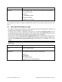
3.7 .......HORIZON COMPACT AUTHENTICATION ........................................................................................56
3.7.1 NO AUTHENTICATION ...............................................................................................................56
3.7.2 UNIQUE AUTHENTICATION .......................................................................................................56
3.7.3 GROUP AUTHENTICATION .........................................................................................................57
3.7.4 AUTHENTICATION POLLING ......................................................................................................57
3.7.5 AUTHENTICATION FAILURE ACTION .........................................................................................57
3.7.6 CONFIGURE AUTHENTICATION .................................................................................................58
3.8 .......THRESHOLD ALARMS ...................................................................................................................63
3.9 .......RAPID LINK SHUTDOWN (RLS) ....................................................................................................67
3.9.1 SETTINGS FOR BASIC MODE......................................................................................................69
3.9.2 SETTINGS FOR ADVANCED MODE .............................................................................................71
3.9.3 RLS LINK CONTROL SETTINGS .................................................................................................71
3.10 ......CONFIGURING THE TIME SOURCE (SNTP)....................................................................................79
3.11 ......AUTOMATIC ADAPTIVE MODULATION .........................................................................................83
3.12 ......HORIZON REDUNDANCY ...............................................................................................................85
3.12.1 BNC CONNECTOR .....................................................................................................................85
3.12.2 HOW AND WHEN PROTECTION SWITCHING OCCURS ................................................................85
3.12.3 RECOVERY TO PRIMARY LINK AFTER PROTECTION SWITCHING HAS OCCURRED ....................86
3.12.4 FORCING THE DATA PATH TO A PARTICULAR LINK ..................................................................86
3.12.5 REDUNDANCY CLI COMMANDS................................................................................................86
3.12.6 TWO WIRE OPTION EXAMPLE ...................................................................................................88
3.12.7 SINGLE WIRE OPTION EXAMPLE ...............................................................................................94
4.0 HORIZON COMPACT MANAGEMENT ............................................................................ 102
4.1 .......MANAGEMENT THROUGH PORT 1 (IN-BAND) ..............................................................................103
4.2 .......MANAGEMENT THROUGH PORT 2 (OUT-OF-BAND) .....................................................................103
4.3 .......TELNET ACCESS .........................................................................................................................104
4.4 .......SECURE SHELL ACCESS SECURITY .............................................................................................105
4.4.1 CONFIGURING SECURE SHELL (SSH)......................................................................................105
4.5 .......HORIZON COMPACT WEB INTERFACE ........................................................................................106
4.5.1 FEATURES ...............................................................................................................................106
4.5.2 CONNECTING TO THE HORIZON COMPACT WEB INTERFACE ...................................................107
4.5.3 EXITING THE APPLICATION .....................................................................................................108
4.5.4 LOGIN .....................................................................................................................................108
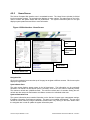
4.5.5 HOME SCREEN ........................................................................................................................110
4.5.6 WEB PAGE TREE DIAGRAM ....................................................................................................111
4.6 .......HORIZON SSL WEB SERVER.......................................................................................................112
4.6.1 WHAT IS SSL? ........................................................................................................................112
4.6.2 GENERATING A CERTIFICATE ON THE HORIZON COMPACT .....................................................113
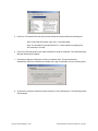
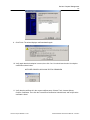
4.6.3 INSTALLING CERTIFICATES ON YOUR WEB BROWSER ............................................................114
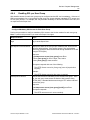
4.6.4 ENABLING SSL PER USER GROUP ...........................................................................................119
4.7 .......EVENT AND PERFORMANCE LOGS ..............................................................................................120
4.8 .......RADIO LOOPBACK ......................................................................................................................123
Horizon Compact Release 1.01.00
Wireless Ethernet Product User Manual – Volume 2
Table of Contents
v
5.0 NETWORK MANAGEMENT OF HORIZON COMPACT .................................................. 125
5.1 .......SIMPLE NETWORK MANAGEMENT PROTOCOL (SNMP) .............................................................125
5.1.1 SUPPORTED SNMP VERSIONS ................................................................................................125
5.1.2 HORIZON COMPACT ENTERPRISE MANAGEMENT INFORMATION BASE (MIB)........................133
5.1.3 SNMP TRAPS..........................................................................................................................133
APPENDIX A – CLI COMMAND LIST ..................................................................................... 139
APPENDIX B – SITE SURVEY INFORMATION ..................................................................... 141
PLANNING .................................................................................................................................................141
SITE SURVEY ............................................................................................................................................141
SITE PREPARATION ...................................................................................................................................142
APPENDIX C - 802.1P PRIORITY TAGGING OVERVIEW..................................................... 143
COS VS QOS .............................................................................................................................................143
Horizon Compact Release 1.01.00
Wireless Ethernet Product User Manual – Volume 2
List of Figures
Figure 2-1 Aligning Antennas Using Local Landmarks ........................................................................ 12
Figure 2-2 Using GPS and Compass Bearings to Align Antennas ...................................................... 12
Figure 2-3 Main and Side Lobes .............................................................................................................. 14
Figure 2-4 Typical main lobe coverage using 23 GHz Radio with 24” antenna.................................. 15
Figure 2-5 Main lobe and side lobes (distance of approximately 4 km).............................................. 16
Figure 2-6 WRONG! Obstruction of the Fresnel Zone........................................................................... 17
Figure 2-7 WRONG! Trees within the Fresnel Zone Obstruct the Signal ............................................ 17
Figure 2-8 Correct & Incorrect Antenna location................................................................................... 19
Figure 3-1 802.1P Enabled on Horizon Compact with Example CoS Allocations .............................. 31
Figure 3-2 CoS Queues can be allocated a CIR and a Committed Burst Size. ................................... 32
Figure 3-3 Redundancy Connections – 2 wire option – copper interface........................................... 88
Figure 3-4 Redundancy Connections – 2 wire option – optical interface ........................................... 89
Figure 3-5 Power Switch Radio Mount.................................................................................................... 94
Figure 3-6 Redundancy Connections – single wire option – copper interface .................................. 95
Figure 3-7 Redundancy Connections – single wire option – optical interface................................... 96
Figure 4-1 Web Interface - Login Screen .............................................................................................. 109
Figure 4-2 Web Interface - Home Screen .............................................................................................. 110
Figure 4-3 Web Interface – Tree Diagram ............................................................................................. 111
Horizon Compact Release 1.01.00
Wireless Ethernet Product User Manual – Volume 2
Table of Contents
vii
List of Tables
Table 2-1 Torque Specifications for Antennas....................................................................................... 11
Table 2-2 Approximate size of beam at destination .............................................................................. 15
Table 2-3 Degrees per Revolution of Adjustment.................................................................................. 18
Table 2-4 Antenna Specifications – Selected radios............................................................................. 18
Table 2-5 Antenna Height vs Obstacle Distance for 24 GHz Unlicensed ............................................ 19
Table 3-1 VLAN Configuration: Network Protocol Strict is OFF. VLAN tagging is OFF ................... 27
Table 3-2 VLAN Configuration: Network Protocol Strict is OFF. VLAN tagging is ON, VLAN tag has
been programmed into Horizon Compact ......................................................................................27
Table 3-3 VLAN Configuration Network Protocol Strict is ON. VLAN tagging is OFF ...................... 28
Table 3-4 VLAN Configuration Network Protocol Strict is ON. VLAN tagging is ON. ....................... 28
Table 3-5 System Mode and Modulation Scheme.................................................................................. 45
Table 3-6 Time Sources ............................................................................................................................ 79
Table 4-1 Simultaneous logins for Web interface...............................................................................109
Table 4-2 Performance Log Durations .................................................................................................. 123
Horizon Compact Release 1.01.00
Wireless Ethernet Product User Manual – Volume 2
This page left blank intentionally
Horizon Compact Release 1.01.00
Wireless Ethernet Product User Manual – Volume 2
1.0 Introduction
Horizon Compact Manual Volume 1 describes the basic requirements for configuring, installing and
aligning a Horizon Compact Ethernet link. Volume 2 (this Volume) provides more in-depth descriptions of
the alignment procedure and explanations as to how the advanced configuration features, noted in
Volume 1, are implemented. Detailed configuration examples are included.
DragonWave Inc.
10
This page left blank intentionally
Horizon Compact Release 1.01.00
Wireless Ethernet Product User Manual – Volume 2
2.0 Aligning the Horizon Compact System
The alignment process is carried out in two stages. The first stage is to visually align the antennas. Once
the antennas have been visually aligned, the second stage is to perform a detailed alignment, which
involves adjusting the fine alignment mechanisms until a maximum received signal is obtained. This
signal should be within ±3 dB of the expected signal level determined during the planning process.
2.1
Visual Alignment of the Horizon Compact Antennas
This section details how to align the Horizon Compact antennas visually.
Procedure 2-1
Align the antennas visually
Before attempting to visually align the Horizon Compact antennas, make sure that the aiming adjustment
mechanisms (pan and tilt) on the mounting system are set to their mid positions. This ensures that there
is adequate to and fro movement available from the adjustment mechanism for fine adjustment later. To
visually align, loosen the clamping nuts and rotate the antenna assembly clamp on the mounting pole,
then, securely tighten the clamp.
There are three methods that are recommended for visually aligning the antennas. In each case the use
of signaling mirrors, on a sunny day, or a powerful flashlight for dull days, may greatly assist in locating
the other end of a link.
1. If the far end antenna site is visible, aim the near end antenna towards the far end site as
accurately as possible. The beamwidth of the signal is approximately 2 degrees (or less), which is
approximately equivalent to a thumb's width when the arm is fully extended. Align as closely to
the centre of the 2-degree beamwidth as possible. Clamp the radio/antenna mounting brackets in
place on the pole/tower torquing the nuts to specification. See Table 2-1 for torque values.
Repeat this for the far end site. This should provide you with a signal strong enough to perform an
accurate alignment later.
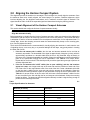
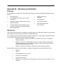
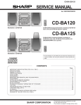
2. If the far end antenna site is NOT visible (due to poor visibility), and the site locations
appear on a map, use a large scale map of the area and mark the positions of each end of the
link. Draw a line on the map between each of the ends of the link. Locate a landmark which falls
on the line that is visible from the near end and point the antenna to the landmark. Clamp the
radio/antenna mounting brackets in place on the pole/tower torquing the nuts to specification. See
Table 2-1 for torque values. At the far end of the link locate a second landmark, visible from the
far end, that falls on the line and align the far end antenna to that landmark. Clamp the mounting
bracket as before. The antennas should be aligned sufficiently to obtain a signal strong enough to
perform an accurate alignment later.
Table
Torque Specifications for Antennas
Bolt size (in inches)
2-1
Nut torque
¼
50 in-lb
5/16
102 in-lb
3/8
15 ft-lb
7/16
24 ft-lb
½
37 ft-lb
9/16
37 ft-lb
Figure 2-1
Aligning Antennas Using Local Landmarks
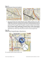
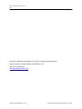
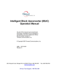
3. If the far end antenna site is NOT visible (due to poor visibility), and there are no visible
land marks, use a GPS unit to obtain accurate coordinates for each end of the link. Plot these on
a map of the area and draw a line between each site. Using a compass, physically align the map
so that the magnetic North compass bearing marked on the map coincides with actual magnetic
North shown on the compass. Use the compass to measure the bearing of the line drawn
between each site relative to magnetic North. At each end of the ink, use this compass bearing to
aim your antennas. Clamp the radio/antenna mounting brackets in place on the pole/tower
torquing the nuts to specification. See Table 2-1 for torque values. The antennas should be
aligned sufficiently to obtain a signal strong enough to perform an accurate alignment later.
Figure 2-2
Using GPS and Compass Bearings to Align Antennas
This concludes the steps to align the radios visually.
Horizon Compact Release 1.01.00
Wireless Ethernet Product User Manual – Volume 2
Aligning the Horizon Compact System
13
2.2
Detailed Alignment of the Horizon Compact Antennas
This section describes how to perform detailed alignment of the Horizon Compact antennas.
Note: The Horizon Compact BNC Field Strength connector serves two purposes. It is used for alignment
and for system redundancy purposes. When used for alignment it provides an output voltage of 1 mV DC
per dB of signal strength. Connecting a digital voltmeter to this connector will provide you with a
convenient way of measuring field strength and confirming antenna alignment. Use the CLI command set
alignment on press Enter, to enable the field strength measuring option. When used for redundancy
purposes ensure that the CLI command set alignment off is used.
The DragonWave Horizon Compact Web Interface may also be used for alignment. From the Home page,
select Tools, then Link Alignment. The RSL readings displayed are continuously updated and the highest
value reached is retained to facilitate the alignment procedure.
When you prepare to align the antennas, you must consider three important factors:
•
The radiation pattern of the Horizon Compact antennas (main lobe and side
lobes)
1. The need for a Clear Line of Sight (LOS)
2. The sensitivity of the alignment adjustment. See Section 2.2.3 for more details.
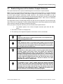
Caution
Alignment of the Horizon Compact requires power to be supplied to the
PonE and surge protector unit.
Caution
Proper alignment results in increased signal quality! Once the Horizon
Compact units have been visually aligned, detailed alignment can begin.
Pan across the entire beamwidth to ensure the alignment corresponds to
the main lobe and not to a Side Lobe.
Caution
Transmission of radio signals results in a primary signal (main lobe) and
secondary signals (side lobes) being sent towards the destination.
During installation the side lobes can be mistaken for the main lobe,
resulting in a 20-30 dB loss of signal strength. On a 12” / 30 cm antenna,
the entire beamwidth typically lies within a 5–degree span so it is critical
to ensure alignment targets the main lobe and not the side lobes. Larger
antennas have a narrower beam. For a 24”/60 cm antenna, the entire
beamwidth lies within a 3–degree span.
Caution
It is possible to get a “peak” reading during the antenna alignment
process if one or both of the antennas is aligned on a side lobe. In such a
case, the measured receive level may be 20 dB or more lower than the
callculated value. Be aware that the link may still function under these
circumstances. If the readings are within 2 - 4 dB of the calculated levels,
then the antennas are most likely to be properly aligned.
Horizon Compact Release 1.01.00
Wireless Ethernet Product User Manual – Volume 2
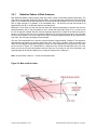
2.2.1
Radiation Pattern of Dish Antennas
Dish antennas radiate a primary signal (main lobe) and a number of secondary signals (side lobes). The
main lobe is the strongest. When you align the radios, you must make sure to align to the main lobe of the
signal. If you mistake the first side side lobe for the main lobe during installation, there can be a 20-30 dB
loss of signal strength. For example, if the Calculated RSL = -42 dB then the side lobe would be at
approximately -62 dB, or 20 dB lower than the calculated level.
Although in most cases only the first two side lobes are detected, depending on antenna size and the
distance between sites, it may be possible to “see” several side lobes (see Figure 2-3). It is wise to pan
the full 35 degrees available with the antenna alignment adjustment to locate all the lobes that may be
present, so that the main lobe can be positively identified. As you pan through the signal, the side lobes
will show up as peaks in the receive signal level (RSL), each peak getting stronger as you approach the
main lobe. The main lobe will always be the strongest.
The size of the beamwidth for the Horizon Compact systems is approximately 2 degrees. Two degrees is
approximately equivalent to a thumb's width when one’s arm is fully extended. Align as closely to the
centre of the 2-degree beamwidth as possible. It takes very little adjustment to swing past the main lobe,
as can be seen in Figure 2-5. A beamwidth of 2 degrees is very narrow and alignment errors can occur
when you lock on to a side lobe instead of onto the main lobe. If you align to one of the side lobes, your
signal strength will be reduced. Make sure you align the antenna to the main lobe.
Note: Verify the RSL is within 2 – 4 dB of the calculated value.
Figure 2-3 Main and Side Lobes
Horizon Compact Release 1.01.00
Wireless Ethernet Product User Manual – Volume 2
Aligning the Horizon Compact System
15
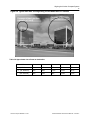
Figure 2-4 Typical main lobe coverage using 23 GHz Radio with 24” antenna
Table 2-2 Approximate size of beam at destination
Beamwidth
1 km
3 km
5 km
8 km
10 km
2˚
35m
105m
175m
280m
350m
1.3˚ (36” antenna)
23m
68m
114m
182m
227m
1˚
18m
54m
90m
144m
175m
(18/24” antenna)
(48” antenna)
Horizon Compact Release 1.01.00
Wireless Ethernet Product User Manual – Volume 2
Figure 2-5
Main lobe and side lobes (distance of approximately 4 km)
Horizon Compact Release 1.01.00
Wireless Ethernet Product User Manual – Volume 2
Aligning the Horizon Compact System
17
2.2.2
Avoid the Fresnel Zone
The Fresnel zone is an area of the antenna radiation pattern that lies mid way between the two system
antennas. The size of this area is dependant upon the frequency being used and the distance between
antennas. You should avoid having any obstructions within the Fresnel zone. Note that you may be able
to see the far end antenna without obstruction, but still have obstacles in the Fresnel Zone. Signal quality
will deteriorate if obstacles encroach too deeply into the Fresnel zone. Encroaching up to the 60% mark is
acceptable.
Figure 2-6 WRONG! Obstruction of the Fresnel Zone
Figure 2-7 WRONG! Trees within the Fresnel Zone Obstruct the Signal
Horizon Compact Release 1.01.00
Wireless Ethernet Product User Manual – Volume 2
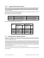
2.2.3
Alignment Adjustment Sensitivity
When aiming the antenna it cannot be over emphasized that you must rotate the adjustment nut(s)
1/10th of a turn at a time between taking RSL readings (allow time for the RSL reading to update).
Table 2-3 shows how many degrees the antenna will move when the adjustment nut(s) is rotated
through one full turn.
Table 2-4 shows that the beam width of the typical antenna is often less than the amount of movement
available with one full turn of the aiming adjustment.
Table 2-3 Degrees per Revolution of Adjustment
Antenna Size
Change in Elevation (Tilt)
Change in Azimuth (Pan)
12” and 24”
2.2 º per full turn of adjustment
1.6 º per full turn of adjustment
36” and 48”
1.3 º per full turn of adjustment
1.1 º per full turn of adjustment
Table 2-4 Antenna Specifications – Selected radios
Antenna
Size
2.3
18 GHz Horizon
23 GHz Horizon
Beamwidth of
main lobe
(degrees, 3 dB)
Gain
dBi
Beamwidth of
main lobe
(degrees, 3 dB)
Gain
dBi
30 cm/12”
3.0 degrees
34
2.7 degrees
35.1
60 cm/24”
2.0 degrees
38.6
1.7 degrees
40.2
90 cm/36"
1.3 degrees
42.0
1.1 degrees
43.7
120 cm/48”
1.0 degrees
44.5
0.8 degrees
46.2
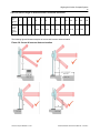
Locating Horizon Compact Antennas
In addition to ensuring that you have a clear line of sight (LoS) between antennas and that there are no
obstructions encroaching into the Fresnel zone, you must pay attention to the location of antennas
relative to objects located close by.
The antenna must be positioned in such a manner as to ensure that obstacles in close proximity to the
antenna do not interfere with the near field RF radiation from the antenna (near field effects). Close
proximity obstacles can cause reflections and severe interference with communications between radios.
This is especially critical for the 24 GHz Unlicensed frequency band, where radios are cross polarized.
Transmit signal reflections change polarity and can be “swallowed” by the receiver, causing swamping
and poor quality reception.
Note that the edge of a roof (roof line) must be considered an obstacle.
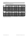
Table 2-5 shows the minimum antenna height requirements above obstacles for the 24 GHz Unlicensed
frequency band.
Horizon Compact Release 1.01.00
Wireless Ethernet Product User Manual – Volume 2
Aligning the Horizon Compact System
19
Table 2-5 Antenna Height vs Obstacle Distance for 24 GHz Unlicensed
Distance
from
Obstacle
(ft)
0
1
2
3
4
5
6
7
8
9
10
20
30
40
>40
Minimum
Antenna
Height
above
Obstacle
(ft)
1
2
3
4
4.36
4.46
4.55
4.64
4.73
4.82
4.91
5.82
6.73
7.64
8
The following figures illustrate examples of correct and incorrect antenna location.
Figure 2-8 Correct & Incorrect Antenna location
Horizon Compact Release 1.01.00
Wireless Ethernet Product User Manual – Volume 2
Near field effects are also experienced above and on each side of the front of an antenna. Ensure that
these areas are also free of obstructions.
Horizon Compact Release 1.01.00
Wireless Ethernet Product User Manual – Volume 2
3.0 Advanced Configuration Features
Volume 1 describes the configuration of the basic features that allow the Horizon Compact to provide a
wireless Ethernet link, with a throughput of up to 400 Mbps. A number of advanced configuration features
provide enhanced access and management security, link protection, quality of service and alarm
management. Each advanced feature is described in detail in the following sub-sections.
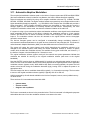
3.1
RADIUS Server User Authentication
The DragonWave Remote Authentication Dial In User Service (RADIUS) server option enables users to
be centrally authenticated before being allowed access to a modem. This adds another layer of security
by removing user access control away from individual modems and moving it to a central server.
However, all modems must have all approved users entered in the modem user authentication list before
the system will grant access at the appropriate user levels (admin, NOC, Super).
Up to five (5) RADIUS servers can be configured.
When one, or more, RADIUS server is configured, the username and password authentication system on
the modem is bypassed, in favour of the RADIUS system. Access levels are still retained in the local
modem memory, so once a user is verified by the RADIUS server the access level is assigned by the
modem (provided that that user is a valid user on that modem). Any user that is validated by the RADIUS
server, but is not found in the modem user authentication list, can gain access to the modem but only at
an admin user level.
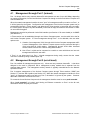
If, on attempting to log in, a user does not receive a response from a configured RADIUS server, the user
will not be allowed to log in. This could be the case if the server was off line. However, the system can be
configured to allow the Super user to still access the modem via the local modem access control, even
when a RADIUS server does not respond.
Only the Super user can issue any of the RADIUS “set” commands and view any of the security related
entries returned with “get” commands (passwords, shared key etc..)
DragonWave Inc.
22
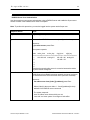
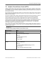
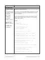
Procedure 3-1
RADIUS Server User Authentication
Use this procedure to set up user authentication using a RADIUS server and enable the Super user to
access a modem if the RADIUS server does not respond.
Note: To perform this procedure, you must be logged into the system as the Super user.
Required Action
Steps
login
Log in using the Super user account.
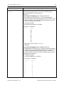
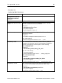
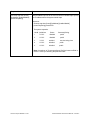
get radius servers
Returns a list of RADIUS servers already configured on the system.
Sequence:
get radius servers press Enter
The system responds:
index active_host
active_key
cfgd_host
cfgd_key
===== =============== =============== ===============
1
192.168.1.48 testing123
192.168.1.48 testing123
2
192.168.1.20
3
4
5
Note that the second radius server is not active because the radius
key has not been configured.
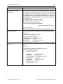
set radius server host
This command sets up a RADIUS server host. Note that once the
RADIUS server host details have been entered, the server key has to
be entered before the server becomes active (see next command).
Sequence:
set radius server host [index] [ip address] press Enter
Where [index] is the server index 1…5 and [ip address] is the ip
address of the RADIUS server concerned
The system responds:
Host set. When server Host and Key are set,
'save mib' and 'reset system' for changes to take effect
Horizon Compact Release 1.01.00
Wireless Ethernet Product User Manual – Volume 2
Advanced Configuration Features
23
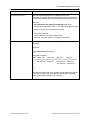
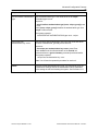
Required Action
Steps
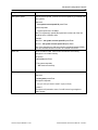
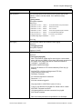
set radius server key
Adds the required shared key to the RADIUS server host
configuration. Note that the previous command has to be issued and
the server key entered before the RADIUS server will become active.
Sequence:
set radius server key [index] [someString] press Enter
Where [index] is the server index 1…5 and [someString] is an alphanumeric string of up to 32 characters in length.
The system responds:
Key set. When server Host and Key are set,
'save mib' and 'reset system' for changes to take effect
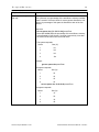
get radius servers
Check that servers have been set up correctly by issuing this
command
Sequence:
get radius servers press Enter
The system responds:
index active_host
active_key
cfgd_host
cfgd_key
===== =============== =============== ===============
1
192.168.1.48 testing123
192.168.1.48 testing123
2
192.168.10.51 password4
3
4
5
Note that the second host is not yet active as the sytem has not been
reset. After a system reset the ip address and key will be repeated
under the active host and active key columns.
Horizon Compact Release 1.01.00
Wireless Ethernet Product User Manual – Volume 2
DragonWave Inc.
24
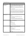
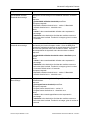
Required Action
Steps
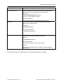
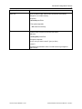
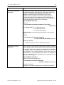
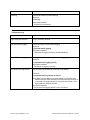
set radius super user
authentication
This commands enables or disables the Super user from accessing a
modem, when the RADIUS server does not respond, or is not
available. If set to “off” the Super user is allowed to log in using the
name and password set in the modem. The default setting is “off”.
Sequence:
set radius super user authentication strict [on/off] press Enter
The system responds:
Radius authentication for Super User is now [strict/not strict]
A save mib command will make this command effective immediately.
WARNING: If super user authentication is set to ON, and the Super
user name and password are not entered into the RADIUS system, the
Super user will not be able to regain access to the modem after a
reset.
get radius super user
authentication strict
This command returns the status of the radius super user.
Sequence:
get radius super user authentication strict press Enter
The system responds:
Radius authentication for Super User is [strict/not strict]
(not strict means SU flash password still works under Radius)
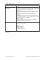
save mib
Saves the MIB to RAM. Perform this command to save setting
changes to non-volatile memory.
Sequence:
save mib press Enter
The system responds:
MIB saved successfully.
Reset system
A system reset is required to activate this feature.
Sequence
reset system press Enter
The system responds:
Are you sure you want to reset? Y(yes) or N(no)
press Y
The system will proceed to reset. You will have to log on again to
regain access.
Horizon Compact Release 1.01.00
Wireless Ethernet Product User Manual – Volume 2
Advanced Configuration Features
25
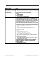
3.2
3.2.1
Management VLAN Tagging
VLAN Tagging Overview
A Local Area Network (LAN) is a single–broadcast domain. If a user broadcasts information on the LAN,
every other user on the LAN receives the broadcast. A router prevents broadcast messages from leaving
a LAN. The result is a reduction in the number of collisions and an improvement in performance.
A network manager can create smaller broadcast domains and reduce network broadcasts by logically
segmenting a LAN into different broadcast domains. These broadcast domains are called Virtual Local
Area Networks (VLANs). Workstations on a VLAN do not have to be physically located together because
they are segmented logically and not physically.
VLANs offer a number of advantages over traditional LANs including:
•
performance
•
security
•
formation of virtual workgroups
•
cost reduction
All ports on a switch are configured for a default VLAN (usually VLAN1). When a switch receives data
from a workstation, the switch tags the data with a VLAN identifier that indicates the originating VLAN.
The switch sends the data to the ports inside the VLAN where the data originated. The switch also sends
the data to a trunking port if one is available.
Network Administrators create VLAN groups and place backbone network devices into the VLAN group to
simplify administration and increase security of the devices. VLAN tagging allows network administrators
to add Horizon Compact nodes to the administrative network. VLAN tagging restricts administrative
access to devices that are members of the VLAN group.
3.2.2
802.1Q Tagging
VLAN Standard: IEEE 802.1q Draft Standard. The Institute of Electrical and Electronic Engineers
(IEEE) is working on a draft standard 802.1q for virtual local area networks. Currently, most products are
proprietary. This means that if you wish to install VLANs, you may have to purchase all products from the
same vendor. DragonWave implements Horizon Compact VLAN Tagging using the IEEE 802.1q
standard. For more information on the Standard, see the Web page:
http://grouper.ieee.org/groups/802/1/pages/802.1Q.html
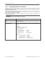
3.2.3
VLAN Tagging Implementation in Horizon
Note: The configuration of Horizon Compact VLAN tagging is only necessary if you wish to restrict
management communications to a Horizon Compact to a specific management VLAN.
The Horizon Compact system will pass user VLAN traffic transparently, independent of the Horizon
Compact VLAN settings. The VLAN settings are for Horizon Compact management purposes and do not
affect user data or traffic. Note that the Horizon Compact system handles Ethernet packet sizes up to
9600 bytes.
There are three parameters associated with Horizon Compact VLAN tagging:
1. Enable or disable VLAN tagging (set VLAN tagging [on/off])
2. Identify the VLAN tag id to be used with Horizon Compact (set VLAN tag [tag id])
Horizon Compact Release 1.01.00
Wireless Ethernet Product User Manual – Volume 2
DragonWave Inc.
26
3. Determine whether to allow Horizon Compact to match the VLAN settings in response
to incoming packets, or whether to restrict responses to those incoming packets
containing the programmed VLAN tag. There are two modes (set network protocol strict
[off/on]) which are commonly known as “friendly” and “strict” mode.
i. “Friendly” mode. In this mode, Horizon Compact matches the VLAN format of
the incoming packet. If an incoming packet contains a VLAN tag, then Horizon
Compact responds with a VLAN tag matching the incoming packet. If the
incoming packet does not contain a VLAN tag then Horizon Compact does not
insert a VLAN tag in the response. Packets generated by Horizon Compact
(e.g. SNMP traps) will contain the programmed VLAN tag.
ii. “Strict” mode. Horizon Compact will only respond to packets containing the
programmed VLAN tag. All other packets will be ignored. Packets generated
by Horizon Compact (e.g. SNMP traps) will always contain the programmed
VLAN tag.
Horizon Compact Release 1.01.00
Wireless Ethernet Product User Manual – Volume 2
Advanced Configuration Features
27
3.2.4
Horizon Compact VLAN Settings
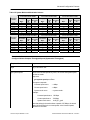
The following tables describe the behavior of Horizon Compact management packets with respect to
VLAN settings on the Horizon Compact system.
Table
VLAN Configuration: Network Protocol Strict is OFF. VLAN tagging is OFF
3-1
Horizon Compact management is set to “friendly” mode due to network protocol strict being set to OFF.
In this configuration Horizon Compact will not generate or respond to VLAN packets.
Condition
Horizon Compact Outgoing Packet
Horizon Compact incoming packet does NOT
contain a VLAN tag
Horizon Compact responds to the packet. There is
no VLAN tag inserted.
Horizon Compact incoming packet contains a
VLAN tag
Horizon Compact inserts VLAN tag in the response
in order to match the VLAN tag of the incoming
packet
Horizon Compact generates a packet (e.g. SNMP
Trap, or software download request to FTP server)
There is no VLAN tag inserted.
FTP Server, SNMP Manager, SNMP Trap Hosts
are NOT on a VLAN
Servers are reachable by Horizon Compact
FTP Server, SNMP Manager, SNMP Trap Hosts
are on a VLAN
Servers are NOT reachable by Horizon Compact
since Horizon Compact does not insert a VLAN tag
into the packet.
Table
3-2
VLAN Configuration: Network Protocol Strict is OFF. VLAN tagging is ON, VLAN tag has been
programmed into Horizon Compact
Horizon Compact management is set to “friendly” mode due to network protocol strict being set to OFF.
In this configuration Horizon Compact will only generate and respond to VLAN packets.
Condition
Horizon Compact Outgoing Packet
Horizon Compact incoming packet does NOT
contain a VLAN tag
Horizon Compact responds to the packet. There is
no VLAN tag inserted.
Horizon Compact incoming packet contains a
VLAN tag
Horizon Compact inserts VLAN tag in the response
in order to match the VLAN tag of the incoming
packet.
Horizon Compact generates a packet (e.g. SNMP
Trap, or software download request to FTP server)
Horizon Compact inserts the programmed VLAN
tag in the response
FTP Server, SNMP Manager, SNMP Trap Hosts
are NOT on a VLAN
Servers are NOT reachable by Horizon Compact
since Horizon Compact inserts a VLAN tag into the
packet and the target is not programmed for VLAN.
FTP Server, SNMP Manager, SNMP Trap Hosts
are on the same VLAN as Horizon Compact
Servers are reachable by Horizon Compact
Horizon Compact Release 1.01.00
Wireless Ethernet Product User Manual – Volume 2
DragonWave Inc.
28
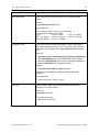
Table
VLAN Configuration Network Protocol Strict is ON. VLAN tagging is OFF
3-3
Horizon Compact management is set to “strict” mode due to network protocol strict being set to ON. In
this configuration VLAN tagging is OFF, therefore no Horizon Compact packets contain VLAN tags.
Condition
Horizon Compact Outgoing Packet
Horizon Compact incoming packet does NOT
contain a VLAN tag
Horizon Compact responds to the packet. There is
no VLAN tag inserted.
Horizon Compact incoming packet contains a
VLAN tag
Horizon Compact does not respond to the incoming
packet. Horizon Compact will not respond to
packets that have a VLAN tag.
Horizon Compact generates a packet (e.g. SNMP
Trap)
There is no VLAN tag inserted.
FTP Server, SNMP Manager, SNMP Trap Hosts
are NOT on a VLAN
Servers are reachable by Horizon Compact.
FTP Server, SNMP Manager, SNMP Trap Hosts
are on the same VLAN as Horizon Compact
Servers are NOT reachable by Horizon Compact
since Horizon Compact does not insert a VLAN tag
into the packet.
Table
VLAN Configuration Network Protocol Strict is ON. VLAN tagging is ON.
3-4
Horizon Compact management is set to “strict” mode due to network protocol strict being set to ON. In
this configuration VLAN tagging is ON, therefore ALL Horizon Compact packets must contain VLAN tags.
Condition
Horizon Compact Outgoing Packet
Horizon Compact incoming packet does NOT
contain a VLAN tag
Horizon Compact does not respond to the packet.
Horizon Compact will only respond to packets that
contain the appropriate VLAN tag.
Horizon Compact incoming packet contains a
VLAN tag
Horizon Compact responds to the packet if the
VLAN tag matches the Horizon Compact
programmed VLAN tag.
Horizon Compact generates a packet (e.g. SNMP
Trap)
Horizon Compact inserts the programmed VLAN
tag in the response.
FTP Server, SNMP Manager, SNMP Trap Hosts
are NOT on a VLAN
Servers are NOT reachable by Horizon Compact.
Horizon Compact does not insert a VLAN tag into
the packet but the target has been programmed for
VLAN.
FTP Server, SNMP Manager, SNMP Trap Hosts
are on the same VLAN as Horizon Compact
Servers are reachable by Horizon Compact since
they have the matching VLAN tag.
Horizon Compact Release 1.01.00
Wireless Ethernet Product User Manual – Volume 2
Advanced Configuration Features
29
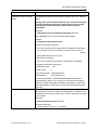
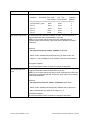
Procedure 3-2
Enable VLAN tagging
Perform this procedure to enable VLAN tagging for the Horizon Compact.
Note: To perform this procedure, you must have NOC user rights.
Required Action
Steps
login
Log in as a NOC user.
get vlan tagging
Displays the VLAN tagging operational state for the system.
Sequence:
get vlan tagging press Enter
The system responds:
VLAN tagging: [off | on]
set vlan tagging [on|off]
Sets the VLAN tagging operational state for the system.
Sequence:
set vlan tagging [off | on ] press Enter
The system responds:
VLAN tagging: [off |on]
set vlan tag [XXXX]
Enables or disables the VLAN tagging operational state you set when
you executed the set vlan tagging command. VLAN tagging follows the
802.1Q standard.
Note: If you set the VLAN tag to the incorrect value, you can lose
remote access to the Horizon Compact. Make sure the VLAN tag
matches your administrative network tag.
Sequence:
set vlan tag [XXXX] [Y]press Enter
where
[XXXX] is the two–byte tag control
[Y] is the priority bit for 802.1P and is in the range of 0-7.
The system responds:
VLAN tag: [XXXX Y]
Horizon Compact Release 1.01.00
Wireless Ethernet Product User Manual – Volume 2
DragonWave Inc.
30
Required Action
Steps
get vlan tag
Displays that the VLAN tagging information for the system. VLAN
tagging is enabled when a valid VLAN tag has been entered using the
set vlan tag command. Note: If you have entered an incorrect VLAN
tag, you cannot communicate remotely with the Horizon Compact.
Sequence:
get vlan tag press Enter
The system responds:
VLAN ID :[ XXXX]
VLAN Priority is [Y]
save mib
Saves the MIB to RAM. Perform this command to save setting
changes to non-volatile memory.
Sequence:
save mib press Enter
The system responds:
MIB saved successfully.
Reset system
A system reset is required to activate this feature.
Sequence
reset system press Enter
The system responds:
Are you sure you want to reset? Y(yes) or N(no)
press Y
The system will proceed to reset. You will have to log on again to
regain access.
This concludes the steps to enable VLAN tagging for the Horizon Compact system using the CLI
manager.
Horizon Compact Release 1.01.00
Wireless Ethernet Product User Manual – Volume 2
Advanced Configuration Features
31
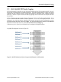
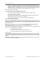
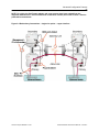
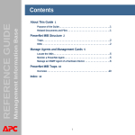
3.3
CoS / QoS 802.1P Priority Tagging
QoS implementation is best done on the ingress and egress portions of the transport network. As such,
QoS should be implemented on the Ethernet switches. Once that implementation is in place, the Horizon
Compact can be configured for QoS, should the potential for congestion exist. Enabling CoS/QoS
(802.1P) on Horizon Compact ensures that the high priority traffic is delivered at the expense of lower
priority traffic.
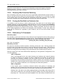
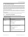
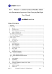
Horizon Compact supports the eight Classes of Service (CoS) levels (0-7) defined within 802.1P. There
are four CoS Queues within Horizon Compact, numbered 1 to 4. Any of the eight CoS levels can be
assigned to any of the four Horizon Compact CoS Queues. Horizon can also be configured to use the
priority bits found in the DSCP field of IP headers. Any frames not having an IP header can be classified
based on the default class of service value (set cos default value [0 though 7]).
In Horizon any, or all, of the four CoS Queues can be configured as expedite queues.
A typical CoS assignment is shown in Figure 3-1
CoS level 0
CoS level 1
CoS level 2
CoS level 3
CoS level 4
CoS level 5
CoS level 6
CoS level 7
Figure 3-1 802.1P Enabled on Horizon Compact with Example CoS Allocations
Horizon Compact Release 1.01.00
Wireless Ethernet Product User Manual – Volume 2
DragonWave Inc.
32
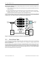
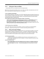
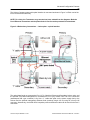
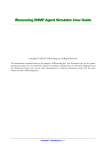
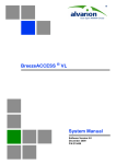
There are three additional Horizon Compact settings that can be used to customize the data flow to
match network requirements:
1. CoS Committed Information Rate (CIR), which determines the guaranteed bandwidth allocated to
a particular Queue.
2. CoS Committed Burst Size, which determines the amount of burst data the Queue can manage.
3. Expedite Queuing (see Section 3.3.4), which allows a Queue to be set as a priority Queue
whereby it delivers its data at the expense of other non-Expedite Queues.
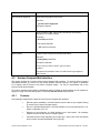
A representative drawing of the QoS components and functional blocks is shown in Figure 3-2. Note that
Queue 4 is shown as being configured as an expedite queue (recommended if only one expedite queue
is desired). Any, or all, of the four queues can be configured as expedite queues.
Queue 1
%n
Queue 2
%n
Ethernet
Frames
In
Frame Filter
Frame
Filter
Queue 3
%n
Rate
Limit
n
Mbps
Ethernet
Frames
Out
Queue 4
%n
(Expedite Queue)
Committed Burst Size
NMS
set filter
Parameters
CIR
for each
Queue
n
n
Depends
depends on
on AirPair
licensed
type and
speed &
radio
system mode
band
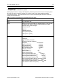
Figure 3-2 CoS Queues can be allocated a CIR and a Committed Burst Size.
3.3.1
Class of Service Types
Horizon Compact has the flexibility to manage the priority requirements of Super VLAN or Q-in-Q framing
as well as standard VLAN frames. Horizon Compact can be configured to manage standard VLAN
frames, or Q-in-Q frames.
For Q-in-Q frames, since a standard VLAN frame is encapsulated within the Q-in-Q frame, there may be
two priority levels associated with the Q-in-Q frame. One will be the priority of the encapsulated, or inner,
VLAN frame and the other will be the priority of the Q-in-Q, or outer, frame. The Horizon Compact class of
service type can be configured to look at the priority levels of either, the inner, or outer, frames and direct
frames to the appropriate Horizon Compact queue.
Horizon Compact Release 1.01.00
Wireless Ethernet Product User Manual – Volume 2
Advanced Configuration Features
33
3.3.2
CoS Committed Information Rate (CIR)
The Horizon Compact system allows the user to assign a percentage of the maximum bandwidth
available to the data flowing in each of the four QoS Queues. Its purpose is to ensure that each Queue
gets at least a portion of the bandwidth and does not get “starved” of bandwidth resulting in no bandwidth
being allocated. If CIR was not available:
•
•
•
•
•
QUEUE 4 would get most of its packets through
QUEUE 3 would get a large percentage of its packets through
QUEUE 2 would get some of its packets through
QUEUE 1 would get very few of its packets through
The “Scheduler” algorithm then progresses as follows:
o QUEUE 4,
o back to QUEUE 4 then to QUEUE 3,
o QUEUE 4 then QUEUE 3 then QUEUE 2,
o QUEUE 4 then QUEUE 3 then QUEUE 2 then QUEUE 1
The scheduler uses it’s algorithm to search for and deliver traffic in each of the Queues, but it also checks
that the CIR rate has been met, and has not been exceeded. If the CIR rate has reached its maximum,
then the scheduler moves on to the next Queue according to its algorithm. For example:
•
•
•
The Scheduler checks QUEUE 4 for packets.
If there is a packet AND the CIR threshold has not been met, then service the Queue.
If the CIR threshold has been exceeded, then jump to QUEUE 3 without processing the packet (in
order to ensure that QUEUE 3 is allocated its CIR bandwidth)
Each Queue can have different maximum bandwidths or information rates assigned to them but the total
CIR cannot exceed 100%. For example:
•
•
•
•
•
Assuming a 200 Mbps system:
With Queue 1 assigned a CIR of 10% (20Mbps) or 25% (50Mbps)
With Queue 2 assigned a CIR of 20% (40Mbps) or 25% (50Mbps)
With Queue 2 assigned a CIR of 30% (60Mbps) or 25% (50Mbps)
With Queue 2 assigned a CIR of 40% (80Mbps) or 25% (50Mbps)
=100%(200Mbps) 100%(200Mbps)
NOTE: See also section 3.3.4 Expedite Queuing
3.3.3
CoS Queue Committed Burst Size
Since IP traffic is “bursty” in nature, the Horizon Compact provides a feature, called CoS Queue
Committed Burst Size (CBS) to handle Ethernet bursts. The Horizon Compact system contains a data
buffer that is used to accommodate bursts of traffic in excess of the user allocated amount as specified
through the CIR setting for each Queue. The buffer is used for traffic bursts only and is functional when
802.1P is enabled on the Horizon Compact system.
The CoS Queue CBS defines the percentage of the total amount of burst buffer that the Queue is
allocated. There is a total of 100 Mbits of buffer allocated to CoS Queues. Each Queue can be allocated
a percentage of this memory. The default allocation for all four Queues is 25%. Each Queue can be
allocated a percentage of the total memory space available for CoS Queues and the total percentage
equals 100%. The CoS Queue CBS function will “smooth out” the output and transmit at the Queue’s
CIR by flushing the burst buffer allocation.
The CoS Queue CBS operates as a FIFO for each individual queue. Burst traffic will be handled as an
extension of the CIR and therefore will be inserted, or interjected, into the Queue as it arrives. This may
have the effect of creating a short delay for subsequent traffic arriving at that Queue if the subsequent
traffic is at that Queue’s CIR level. Conversely, if the burst is followed by traffic that is less than the CIR
Horizon Compact Release 1.01.00
Wireless Ethernet Product User Manual – Volume 2
DragonWave Inc.
34
level, then no delay should occur. This technique prevents out of order packets over the Horizon Compact
system.
For example: QUEUE 3 has 25% CIR or 25 Mbps on a 100 Mbps link. The CoS Queue CBS is set to
25% or 25 Mbits. If Queue 3 receives a burst of traffic in excess of 25 Mbps then QUEUE 3 would
continue to transmit at 25 Mbps until the 25 Mbit “burst buffer” is empty, regardless of whether or not the
the traffic source is sending packets. If the traffic source continues to send packets then the original 25
Mbps is transmitted, followed by the “burst buffer” traffic, followed by new incoming packets.
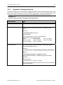
3.3.4
Expedite Queuing
Expedite Queuing is a mechanism that allows one or more of the 4 Queues to transmit its data as priority
traffic, at the expense of the remaining Queues. When Expedite Queue feature is enabled, then as long
as there is data in the Expedite Queue, or Queues, that data will be transmitted first. This allows time
critical, or error-sensitive, traffic to have priority data delivery.
The Horizon Compact system allows the user to configure one or more Queues as “expedite” Queues.
Any or all of the 4 Queues can be made into Expedite Queues. This allows custom configurations such
as QUEUE 4 = Voice, QUEUE 3 = Video over IP, QUEUE 2 = database transfers, QUEUE 1 = Internet
email, Web, etc. The Scheduler continues to service QUEUE 4 through QUEUE 1 in order, however
when a Queue is set as an Expedite Queue it will service the Expedite Queue first and continue to service
it until it is empty. After the Expedite Queue has been flushed of data, the Scheduler will continue to
service the other Queues according to its main algorithm.
To configure a Queue to be an Expedite Queue (once the “set Expedite Queue on” command has been
issued”) assign the CIR for that Queue to 100%. Each of the 4 Queues can be assigned a CIR of 100%.
The total CIR can now be greater than 100%, up to a maximum of 400% (4 Queues). A total CIR of
400% means ALL 4 Queues are Expedite Queues and each one can use 100% of the bandwidth. It
does not mean the Horizon Compact system can achieve 400% of the Horizon Compact maximum
bandwidth, simply that if any bandwidth is available after a previous Queue has been serviced, the
next Queue in line will be given full access to the remaining bandwidth until fully serviced. IF
Expedite Queuing is turned OFF, then the total CIR cannot exceed 100%.
As network services increase, the need for multiple Expedite Queues becomes evident. A network
administrator may require 3 Expedite Queues and decide to send all network routing protocols through
the highest Expedite Queue, send IP Voice through the next highest Expedite Queue, send Video over IP
through the next highest Expedite Queue. Send all other traffic to the remaining Queue, which is not
configured as an Expedite Queue. To do this, the administrator would configure Queues 4,3 and 2 as
Expedite Queues and configure Queue 1 as a standard Queue with a particular CIR.
3.3.5
Operation of QoS using multiple Expedite Queues
When multiple Expedite Queues are enabled, the Scheduler will continue to follow in the same
sequence/rules as the previous release.
The sequence is:
• Service QUEUE 4
• Recheck QUEUE 4 and if empty, service QUEUE 3
• Recheck QUEUE 4 and if empty, check QUEUE 3 and if empty, service QUEUE 2
• Recheck QUEUE 4 and if empty, check QUEUE 3 and if empty, check QUEUE 2 and if
empty, service QUEUE 1
Each Queue having 100% CIR (priority) will be serviced until empty, then the Scheduler moves on to the
next priority Queue. The effect of setting a Queue as an Expedite Queue is to override the Scheduler’s
sequence and force it to service the Expedite Queue first and continue to service it until empty. Any
Queue can be configured as an Expedite Queue and therefore override the Scheduler’s sequence. For
example: if Queue 1 is set as the only Expedite Queue then QUEUE 1 will be serviced first, followed by
Queue 4 then Queue 3 then Queue 2. At any time, should data arrive in Queue 1, then the Scheduler will
“jump” to Queue 1 in order to service it.
Horizon Compact Release 1.01.00
Wireless Ethernet Product User Manual – Volume 2
Advanced Configuration Features
35
Example 1: Queues configured with the following settings :
• QUEUE 4 = 100%
• QUEUE 3 = 100%
• QUEUE 2 = 75%
• QUEUE 1 = 25%
• In this example, voice traffic could be assigned to QUEUE 4, IPTV could be assigned to
QUEUE 3, Database transfers assigned to QUEUE 2, and Internet traffic assigned to QUEUE
1
• QUEUE 4 is serviced as a priority Queue until empty
• QUEUE 3 is serviced as a priority Queue until empty or until QUEUE 4 receives packet
• If neither QUEUE 4 or QUEUE 3 have packets, service QUEUE 2 until empty or CIR limit is
met, or until QUEUE 4 or QUEUE 3 packets arrive
• Service QUEUE 1 when no other packets exist in QUEUE 4, QUEUE 3, QUEUE 2 and
QUEUE 1 CIR limit has not been met
Example 2: Assuming that the total bandwidth available is 200Mbps, if the Expedite Queue is “ON” and
the CIR for the remaining Queues are set to:
• QUEUE 4 = 100%
• QUEUE 3 = 100%
• QUEUE 2 = 0%
• QUEUE 1 = 0%
In this scenario, with Expedite Queue “on” and QUEUE 4 set to 100%, QUEUE 4 will be given priority
access to the full bandwidth available on the link.
Once QUEUE 4’s throughput requirements have been satisfied, 100% of any remaining bandwidth
will be given to QUEUE 3.
Will allow the user to set the system up with a “prioritized Expedite Queue” configuration, whereby
QUEUE 4 gets full bandwidth until satisfied, and then QUEUE 3 gets100% of what is left over. (useful
in applications where 2 types of “high priority traffic” need to be serviced)
Note that in this example untagged traffic or traffic assigned to Queues 1 or 2 will not be transmitted
due to QUEUE 1 being set to 0% CIR.
Example 3: Assuming that the total bandwidth available is 200Mbps, if the Expedite Queue is “ON” and
the CIR for the remaining Queues are set to:
• QUEUE 4 = 100%
• QUEUE 3 = 50%
• QUEUE 2 = 50%
• QUEUE 1 = 100%
In this scenario, with Expedite Queue “on”, and QUEUE 4/QUEUE 1 set to 100%, QUEUE 4 will be
given priority access to the full bandwidth available on the link (200Mbps). When its traffic
commitments have been met, QUEUE 1 will then be given the remaining available bandwidth to
service its incoming traffic. Once QUEUE 4 and QUEUE 1’s requirements have been met, QUEUE 3
will be serviced by the scheduler up to but not beyond its CIR limit (should any bandwidth be
available). Once QUEUE 4, QUEUE 1 and QUEUE 3 have been serviced, QUEUE 2 will receive any
remaining bandwidth to service its incoming traffic.
Example: QUEUE 4 and QUEUE 1 each have 70Mbps of traffic to service (140Mbps). The
scheduler first handles QUEUE 4’s requirements, then QUEUE 1’s, which leaves 60Mbps of
bandwidth available for QUEUE 3 and QUEUE 2. If QUEUE 3 and QUEUE 2 both have 50Mbps of
incoming traffic, the scheduler will service QUEUE 3 first, up to but not beyond its CIR limit of
50Mbps. The remaining 10Mbps will be dedicated to QUEUE 2 as long as no packets arrive in
QUEUE 4 or QUEUE 1.
Horizon Compact Release 1.01.00
Wireless Ethernet Product User Manual – Volume 2
DragonWave Inc.
3.3.6
36
Operation with 802.1P Priority Queuing Disabled
If 802.1P filtering is disabled in the Horizon Compact system, all incoming packets are treated equally and
are forwarded on a first-come first-served basis. The system operates in a FIFO (First In First Out) basis.
If the Pause Frames feature (see Section 3.4) is enabled, pause frames will be sent to the connected
switch when the input buffer is close to being full (internally set threshold). This allows time for the queue
to empty prior to more frames being received and thus avoids congestion.
3.3.7
Operation with 802.1P Priority Queuing Enabled
If 802.1P filtering is enabled in the Horizon Compact system, the scheduling mechanism can be
described as follows:
1. Select the highest priority queue which has a packet in it
2. Send that packet
If COS CIRs are set for the queues, then the scheduling mechanism can be described as follows:
1. Select the highest priority queue which has a packet in it, and hasn’t used up its CIR budget
2. Send that packet
The operation of the Scheduler is affected by both the user-configurable CIR and CoS Queue CBS
settings.
If the Pause Frames feature (see Section 3.4) is enabled, pause frames will be sent to the connected
switch when the input buffer is close to being full (internally set threshold).
The Horizon Compact system also allows any packets without a VLAN tag to be allocated an 802.1P CoS
level (“set untagged packet priority”). If the “set untagged packet priority” is not configured, then all
untagged packets will be forwarded through Queue 1.
Horizon Compact is also able to manage Q-in-Q or Super VLAN traffic. The system can be configured to
use either an encapsulated frame’s priority tag or the encapsulating frame’s priority tag, in determining
priority handling.
3.3.8
Management Traffic
Slow Ethernet services and multicast packets are handled by a special Queue inside the Horizon
Compact. The Queue is not user-accessible. It works similar to an Expedite Queue in that it ensures
management traffic is passed through in an “expedited” fashion. It does not affect, nor is related to the
four Queues within Horizon Compact.
Packets destined for the 01-80-C2-00-00-xx MAC addresses are sent to the internal Queue. Examples:
STP, RSTP, MSTP LACP, Pause Frames, GARP (GMRP,GVRP), bridge broadcasts, OAM, LLDP, Port
based authentication are all sent to the internal Queue and are transmitted in an expedited fashion.
Other packets that the user determines must be treated in an expedited fashion, such as “keep-alive”
packets and MRP packets, must be assigned a CoS within the switch, then assigned to the appropriate
Queue within Horizon Compact.
Horizon Compact Release 1.01.00
Wireless Ethernet Product User Manual – Volume 2
Advanced Configuration Features
37
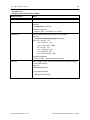
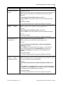
Procedure 3-3
Enable 802.1P Priority Queuing
Perform this procedure to enable 802.1P Priority Queuing for the Horizon Compact.
Note: To perform this procedure, you must have NOC user rights.
Required Action
Steps
login
Log in as a NOC user.
set qos [on/off]
Enables or disables (on or off) quality of service (QoS) on the Horizon
Compact system. QoS is part of the 802.1P specification.
Sequence:
set qos [on/off] press Enter
where on will enable QoS and off will disable QoS
The system responds:
qos is : [on/off]
set cos type
Sets the CoS system to handle VLAN or Q-in-Q frame formats.
Sequence:
set cos type
[cos_vlan/cos_qinq_itag/cos_qinq_otag/cos_dscp] press Enter
The system responds:
CoS type is set to :
cos_vlan/cos_qinq_itag/cos_qinq_otag/cos_dscp
Note: cos_vlan uses the priority tag of standard VLAN frames
cos_qinq_itag uses the inner priority tag of a Q-in-Q frame
cos_qinq_otag uses the outer priority tag of a Q-in-Q frame
cos_dscp uses the 3 bit priority information in the DSCP field
of the IP header (also referred to as ToS).
Horizon Compact Release 1.01.00
Wireless Ethernet Product User Manual – Volume 2
DragonWave Inc.
38
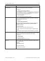
Required Action
Steps
set cos queue mapping [x x x
x x x x x]
Assigns each of the incoming 802.1P CoS levels to either of the four
Horizon Compact CoS Queues. The Horizon Compact system
supports all eight 802.1P CoS levels (0-7).
Sequence:
set cos queue mapping [x x x x x x x x ] press Enter
where each x is a value of either 1, 2, 3 or 4 representing the
Horizon Compact CoS Queues allocated to each of the 801.1P CoS
levels (0-7) in order. Any values not explicitly assigned by the user
will not be affected by the command.
The system responds:
dot1p Queue assignment is as follows :
dot1p value CoSQueue
-----------
-- ---------
0
[x]
1
[x]
2
[x]
3
[x]
4
[x]
5
[x]
6
[x]
7
[x]
Where [x] is a value of either 1, 2, 3 or 4
Examples:
set cos queue mapping [1 1 2 2 3 3 3 4 ] press Enter
will allocate 802.1P CoS levels 0-1 to Horizon Compact CoS Queue
1, CoS levels 2-3 to Horizon Compact CoS Queue 2 CoS levels 4-6.
to Horizon Compact CoS Queue 3 and CoS level 7 to Horizon
Compact CoS Queue 4. Note that there is a space between each of
the digits in the command.
The system responds:
cos queue assignment is as follows :
dot1p value CoSQueue
-----------
Horizon Compact Release 1.01.00
-- ---------
0
1
1
1
2
2
3
2
4
3
5
3
6
3
7
4
Wireless Ethernet Product User Manual – Volume 2
Advanced Configuration Features
39
Required Action
Steps
set cos expedite queue
Enables or disables the expedite queue function. Expedite queues are
processed first, prior to any other queue being processed. This allows
the user to force the system to transmit high priority traffic before lower
priority traffic.
Sequence:
set cos expedite queue [on/off]
The system responds:
Expedite queue is :on/off
set cos queue cir [%1 %2 %3
%4]
Sets the Committed Information Rate (CIR) for each of the 4 CoS
Queues. The CIR defines the minimum amount of bandwidth allocated
for that Queue. Note that Queues set as Expedite Queues can
override the CIR for other Queues should congestion occur.
Sequence:
set cos queue cir [%1 %2 %3 %4] press Enter
where %1 %2 %3 %4 is the percentage of the total Queue memory to
be allocated to CoS Queues 1 through 4 respectively. The total
cannot exceed 100% unless Expedite Queuing has been enabled.
The system responds: (example shown using 25% settings for each
queue)
Expedite queue is :off.
All queues bandwidth are guaranteed.
Queue
CIR(%)
CIR(Mbps)
1
25
25
2
25
25
3
25
25
4
25
25
If Expedite Queuing has been enabled, then each queue that has been
configured for 100% CIR is treated as an Expedite Queue.
Sequence:
set cos queue cir 25 100 25 100
The system responds:
Expedite queue is :on
Bandwidth for higher priority queues are guaranteed over
lower priority queues
Queue
CIR(%)
1
25
25
CIR(Mbps)
2
100
Full
3
25
25
4
100
Full
“Full” indicates that the queue is an Expedite Queue and can consume
the full bandwidth of the Horizon Compact.
Horizon Compact Release 1.01.00
Wireless Ethernet Product User Manual – Volume 2
DragonWave Inc.
40
Required Action
Steps
set cos queue cbs [%1 %2
%3 %4]
Sets the committed burst size for each of the four Class of Service
(CoS ) Queues, as a percentage of the total Queue memory available.
There is a total of 100 msec worth of memory space allocated to CoS
Queues. A percentage of this space is allocated to each of the four
Queues.
Sequence:
set cos queue cbs [%1 %2 %3 %4] press Enter
where %1 %2 %3 %4 is the percentage of the total Queue memory
to be allocated to CoS Queues 1 through 4 respectively. Note that
the total of all Queues must not exceed 100%
The system responds:
Queue
Size (%)
1
%1
2
%2
3
%3
4
%4
Example:
get cos queue cbs press Enter
The system responds:
Queue
Size (%)
1
25
2
25
3
25
4
25
set cos queue cbs 10 20 30 40 press Enter
The system responds:
Horizon Compact Release 1.01.00
Queue
Size (%)
1
10
2
20
3
30
4
40
Wireless Ethernet Product User Manual – Volume 2
Advanced Configuration Features
41
Required Action
Steps
set cos default value
Assigns packets that do not have CoS levels (not complying with
802.1P) to any one of the eight 802.1P CoS levels (0-7).
Sequence:
set cos default value [n] press Enter
where “n” is any number 0 through 7.
The system responds:
Packets without VLAN tag are treated as 802.1p priority: n
save mib
Saves the MIB to RAM. Perform this command to save setting
changes to non-volatile memory.
Sequence:
save mib press Enter
The system responds:
MIB saved successfully.
Reset system
A system reset is required to activate this feature.
Sequence
reset system press Enter
The system responds:
Are you sure you want to reset? Y(yes) or N(no)
press Y
The system will proceed to reset. You will have to log on again to
regain access.
This concludes the steps to configure 802.1P Priority Queuing using the CLI manager.
Horizon Compact Release 1.01.00
Wireless Ethernet Product User Manual – Volume 2
DragonWave Inc.
3.4
42
Pause Frames
Pause frames are generated by the weaker (slower) link when its forward pipe gets full. Pause frames
inform the upstream device to “pause and stop sending traffic for a period of 5 msec”. When the Pause
Frame feature is enabled, Horizon Compact generates pause frames to the Ethernet switch when the
Horizon Compact receiving buffer hits the internally set threshold. The receiving buffer threshold is close
to 100 msec at GigE rate. At data rates lower than GigE, the data buffer will accommodate a lesser
amount of data. The Pause Frame feature can be used when CoS/QoS is enabled or disabled.
Procedure 3-4
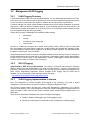
Configuring the Pause Frames feature
Perform this procedure to enable or disable pause frames for the Horizon Compact.
Note: To perform this procedure, you must have NOC user rights.
Required Action
Steps
login
Log in as a NOC user.
get pause state
Returns the current state of the pause frame feature.
Sequence:
get pause state press Enter
The system responds:
Asymmetric PAUSE is on/off.
set pause state
Enables or disables the pause frame feature.
Sequence:
set pause state [on/off] press Enter
The system responds:
This may affect user traffic. Continue? Enter Y(Yes) or N(No):Y
Asymmetric PAUSE is : on, PAUSE frames can flow towards the
link partner.
save mib
Saves the MIB to RAM. Perform this command to save setting
changes to non-volatile memory.
Sequence:
save mib press Enter
The system responds:
MIB saved successfully.
Horizon Compact Release 1.01.00
Wireless Ethernet Product User Manual – Volume 2
Advanced Configuration Features
43
3.5
Horizon Compact Throughput Speed
When you purchase a Horizon Compact system you receive a unit capable of giving a throughput speed
of up to 400 Mbps. However, the actual throughput speed achievable for any given system depends on
the specific licensed speed key that you purchased with the system
You can upgrade your system to a higher licensed speed by purchasing an upgrade key and
reprogramming your system. Any upgraded system can be reconfigured to a lower system speed (CLI
command set system speed) as required, without losing the ability to return to the upgraded licensed
speed.
You may also downgrade the licensed speed to a lower value. A downgraded system may warrant a
refund of licensing fees. Once downgraded, new upgrade keys will be required for future upgrading.
System speeds do not have to be symmetrical (same speed in both directions on the link). Asymmetric
speeds (different speeds in each direction) can also be configured.
3.5.1
Maximum Throughput Speed
The maximum throughput speed is determined by the Horizon Compact licensed speed key you
purchase, however, it is important to note that the maximum speed is also determined by the Channel
bandwidth associated with the configured radio band, and the modulation scheme used. The channel
bandwidth is a function of the radio band and the modulation scheme is selected depending on the
desired maximum throughput. Configuring the Radio Band and System Mode determines the maximum
throughput capability and the modulation scheme applied.
Note that if a System Mode is set with a maximum throughput capability that exceeds the licensed speed
key purchased from DragonWave, then the maximum speed attainable will be limited to the licensed
speed purchased. By default the system speed is set to the licensed speed key purchased, however, it
can be reduced to a lower level without losing the ability to return to the purchased licensed speed.
(combination of channel bandwidth and maximum throughput).
Horizon Compact Release 1.01.00
Wireless Ethernet Product User Manual – Volume 2
DragonWave Inc.
44
Table 3-5 System Mode and Modulation Scheme
Channel Bandwidth 50 MHz
Modulation
scheme
Channel Bandwidth 40 MHz
Mbps
TX
Power
dB
QPSK
67
17/27
16 QAM
110
14.5/24.5
-78
110
14.5/24.5
-75
32 QAM
171
14/24
-73
143
14.5/24.5
64 QAM
215
12.5/22.5
-69
181
128 QAM
271
11/21
-66
256 QAM
322
11.5/21.5
-60
256 QAM
371
9.5/19.5
-60
Throughput
RX
Sensitivity
dB
Throughput
-81
Channel Bandwidth 56/55 MHz
Modulation
scheme
Throughput
Mbps
TX
Power
dB
RX
Sensitivity
dB
QPSK
Mbps
TX
Power
dB
RX
Sensitivity
dB
58
17/27
-81
Channel Bandwidth 30 MHz
Mbps
TX
Power
dB
-74
107
14.5/24.5
-75
12.5/22.5
-70
128
12.522.5
-72
212
11/21
-67
165
11/21
-68
277
9.5/19.5
-61
212
9.5/19.5
-62
Channel Bandwidth 28 MHz
Mbps
TX
Power
dB
RX
Sensitivity
dB
37
17/27
-83
Throughput
Throughput
RX
Sensitivity
dB
Channel Bandwidth 14 MHz
Mbps
TX
Power
dB
Throughput
RX
Sensitivity
dB
QPSK
65
17/27
-80
48
13.5/23.5
-82
23
13.5/23.5
-85
16 QAM
111
14.5/24.5
-77
71
13/23
-79
36
13/23
-82
-78
32 QAM
216
11/21
-72
100
11/21
-75
47
13/23
128 QAM
290
10.5/20.5
-66
144
10.5/20.5
-69
70
10.5/20.5
-72
256 QAM
385
9.5/19.5
-60
190
9.5/19.5
-63
95
9.5/19.5
-66
shows the modulation schemes that are selected for various System Modes (combination of channel
bandwidth and maximum throughput).
Horizon Compact Release 1.01.00
Wireless Ethernet Product User Manual – Volume 2
Advanced Configuration Features
45
Table 3-5 System Mode and Modulation Scheme
Channel Bandwidth 50 MHz
Modulation
scheme
Channel Bandwidth 40 MHz
Mbps
TX
Power
dB
QPSK
67
17/27
16 QAM
110
14.5/24.5
-78
110
14.5/24.5
-75
32 QAM
171
14/24
-73
143
14.5/24.5
64 QAM
215
12.5/22.5
-69
181
128 QAM
271
11/21
-66
256 QAM
322
11.5/21.5
-60
256 QAM
371
9.5/19.5
-60
Throughput
RX
Sensitivity
dB
Throughput
-81
Channel Bandwidth 56/55 MHz
Modulation
scheme
Throughput
Mbps
TX
Power
dB
Mbps
TX
Power
dB
RX
Sensitivity
dB
58
17/27
-81
Mbps
TX
Power
dB
-74
107
14.5/24.5
-75
12.5/22.5
-70
128
12.522.5
-72
212
11/21
-67
165
11/21
-68
277
9.5/19.5
-61
212
9.5/19.5
-62
Channel Bandwidth 28 MHz
RX
Sensitivity
dB
QPSK
Channel Bandwidth 30 MHz
Mbps
TX
Power
dB
RX
Sensitivity
dB
37
17/27
-83
Throughput
Throughput
RX
Sensitivity
dB
Channel Bandwidth 14 MHz
Mbps
TX
Power
dB
Throughput
RX
Sensitivity
dB
QPSK
65
17/27
-80
48
13.5/23.5
-82
23
13.5/23.5
-85
16 QAM
111
14.5/24.5
-77
71
13/23
-79
36
13/23
-82
-78
32 QAM
216
11/21
-72
100
11/21
-75
47
13/23
128 QAM
290
10.5/20.5
-66
144
10.5/20.5
-69
70
10.5/20.5
-72
256 QAM
385
9.5/19.5
-60
190
9.5/19.5
-63
95
9.5/19.5
-66
Procedure 3-5
Configure Horizon Compact Throughput Speed (Symmetrical Throughput)
Required Action
Steps
login
Log in as a NOC user.
get system speed
Returns the licensed speed key value, the current set system speed
and the set mode.
Sequence:
get system speed press Enter
The system responds:
Licensed speed set to
: n Mbps
Current speed set to
: n Mbps
System mode set to
: <system mode>
Example:
Licensed speed set to :50 Mbps
Current speed set to
:50 Mbps
System mode set to
:hc50_67_qpsk
Note that although the mode shows a speed of 67 Mbps, the actual
speed will be limited to the current speed, or the licensed speed,
whichever is the lower.
Horizon Compact Release 1.01.00
Wireless Ethernet Product User Manual – Volume 2
DragonWave Inc.
46
Required Action
Steps
get system mode
Returns the current system mode and a list of available system
modes.
Sequence:
get system mode press Enter
System responds:
Current system mode is :hc50_67_qpsk (Example)
System modes available in the system:
cw_test
hc50_67_qpsk
hc50_110_16qam
hc50_171_32qam
hc50_215_64qam
hc50_271_128qam
hc50_322_256qam
hc50_371_256qam
set system mode
Sets the system mode (channel bandwidth, maximum throughput
speed and modulation scheme). You can only select any one of the
modes shown as available when the get system mode command is
used.
Sequence:
set system mode <hc[bandwidth]_[throughput]_[modulation]>
Where [bandwidth] is the channel bandwidth of the configured
radio band; [throughput] is the maximum throughput capability in
Mbps; [modulation] is the modulation scheme.
Example:
set system mode hc50_67_qpsk press Enter
(50 MHz channel bandwidth, 67 Mbps throughput and QPSK
modulation.
System responds:
System mode set to :hc50_67_qpsk
save mib
Saves the MIB to RAM. Perform this command to save setting
changes to non-volatile memory.
Sequence:
save mib press Enter
The system responds:
MIB saved successfully.
Horizon Compact Release 1.01.00
Wireless Ethernet Product User Manual – Volume 2
Advanced Configuration Features
47
Required Action
Steps
Reset system
A system reset is required to activate this feature.
Sequence
reset system press Enter
The system responds:
Are you sure you want to reset? Y(yes) or N(no)
press Y
The system will proceed to reset. You will have to log on again to
regain access.
Horizon Compact Release 1.01.00
Wireless Ethernet Product User Manual – Volume 2
DragonWave Inc.
3.5.2
48
Asymmetric Throughput Speed
Asymmetric throughput can be achieved by installing the same Horizon Compact hardware type at each
end of the link, and configuring one end with a different system speed. Note, that the System Mode, must
be identical at each end of the link for this to work. The variable will be the system speed figure.
Procedure 3-6
Configure Horizon Compact Throughput Speed (Asymmetric)
Required Action
Steps
login
Log in as a NOC user.
get system mode
Returns the current system mode and a list of available system
modes.
Sequence:
get system mode press Enter
System responds:
Current system mode is :hc50_67_qpsk (Example)
System modes available in the system:
cw_test
hc50_67_qpsk
hc50_110_16qam
hc50_171_32qam
hc50_215_64qam
hc50_271_128qam
hc50_322_256qam
hc50_371_256qam
set system mode
Sets the system mode (channel bandwidth, maximum throughput
speed and modulation scheme).
Sequence:
set system mode <hc[bandwidth]_[throughput]_[modulation]>
Example:
set system mode hc50_110_16qam press Enter
(50 MHz channel bandwidth, 110 Mbps throughput and 16QAM
modulation.
System responds:
System mode set to :hc50_110_16qam
Note: For asymmetric speeds, the system mode must be set identically
at each end of the link.
Horizon Compact Release 1.01.00
Wireless Ethernet Product User Manual – Volume 2
Advanced Configuration Features
49
Required Action
Steps
Set system speed
Sets the system speed. (Cannot exceed the speed key purchased with
your system).
Sequence:
set system current speed 50 press Enter
System responds:
System speed set to 50 Mbps
Note: For asymmetric speeds the speed at the other end of the link
would be set to a different value.
Example:
Near end – set system current speed 50 press Enter
Far end – set system current speed 100 press Enter
Note: if the speed at one end was to be the purchased speed (default),
then this command would not need to be invoked at that end.
save mib
Saves the MIB to RAM. Perform this command to save setting
changes to non-volatile memory.
Sequence:
save mib press Enter
The system responds:
MIB saved successfully.
Reset system
A system reset is required to activate this feature.
Sequence
reset system press Enter
The system responds:
Are you sure you want to reset? Y(yes) or N(no)
press Y
The system will proceed to reset. You will have to log on again to
regain access.
Horizon Compact Release 1.01.00
Wireless Ethernet Product User Manual – Volume 2
DragonWave Inc.
3.5.3
50
Upgrading System License Speed
Upgrading the system licensed speed requires an upgrade license key obtainable from DragonWave.
Upgrading the licensed speed does not cause you to lose the ability to reduce the speed and then return
to the new licensed speed at a later time.
Note that the licensed speed is the maximum speed that the system can operate at, regardless of the
setting of the System Mode.
Procedure 3-7
Upgrading Horizon Compact System License Speed
Required Action
Steps
login
Log in as a NOC user.
get system speed
Returns the licensed speed key value, the current set system speed
and the set mode.
Sequence:
get system speed press Enter
The system responds:
Licensed speed set to
: n Mbps
Current speed set to
: n Mbps
System mode set to
: <system mode>
Example:
Licensed speed set to :50 Mbps
Current speed set to
:50 Mbps
System mode set to
:hc50_67_qpsk
Note that although the mode shows a speed of 67 Mbps, the actual
speed will be limited to the current speed, or the licensed speed,
whichever is the lower.
Upgrade system licensed
speed
Upgrades the system to operate at a higher speed. A license key is
required for this command. Contact DragonWave.
Sequence:
upgrade system licensed speed [speed] [key] press Enter
Where [speed] is the new licensed speed, and [key] is the license key
obtained from DragonWave
Horizon Compact Release 1.01.00
Wireless Ethernet Product User Manual – Volume 2
Advanced Configuration Features
51
Required Action
Steps
save mib
Saves the MIB to RAM. Perform this command to save setting
changes to non-volatile memory.
Sequence:
save mib press Enter
The system responds:
MIB saved successfully.
Reset system
A system reset is required to activate this feature.
Sequence
reset system press Enter
The system responds:
Are you sure you want to reset? Y(yes) or N(no)
press Y
The system will proceed to reset. You will have to log on again to
regain access.
Horizon Compact Release 1.01.00
Wireless Ethernet Product User Manual – Volume 2
DragonWave Inc.
3.5.4
52
Downgrading System License Speed
Downgrading the system license speed to a value lower than previously purchased is supported.
Information presented by the system, when downgraded, needs to be sent to DragonWave in order to
confirm the status of your license.
NOTE: Once the system license speed has been downgraded, a new license key is required if you
wish to return to a higher licensed speed.
Note that the licensed speed is the maximum speed that the system can operate at, regardless of the
setting of the System Mode.
Procedure 3-8
Downgrading Horizon Compact System License Speed
Required Action
Steps
login
Log in as a NOC user.
get system speed
Returns the licensed speed value, the current set system speed and the
set mode.
Sequence:
get system speed press Enter
The system responds:
Licensed speed set to
: n Mbps
Current speed set to
: n Mbps
System mode set to
: <system mode>
Example:
Licensed speed set to :400 Mbps
Horizon Compact Release 1.01.00
Current speed set to
:400 Mbps
System mode set to
:hc50_364_256qam
Wireless Ethernet Product User Manual – Volume 2
Advanced Configuration Features
53
Required Action
Steps
Downgrade system licensed
speed
Downgrades the system licensed speed to operate at a lower maximum
speed.
Warning: Once you issue this command your current license speed
key will be lost and you will not be able to return to your original
licensed speed without acquiring another license key from
DragonWave.
Sequence:
downgrade system licensed speed [speed] press Enter
Where [speed] is the new lower licensed speed in Mbps.
Example:
downgrade licensed speed to 200
The system responds: (Example)
The current system licensed speed will be downgraded to 200 Mbps.
This operation will force to save Mib. Continue? Enter Y(Yes) or
N(No):y
Saving MIB. Please wait for a while...
Mib saved successfully.
The current system licensed speed is downgraded to 200 Mbps.
Downgrade Confirmation Information:
Speed Decrement
Speed Count
:200
:2
Unit Serial Number :DW130AAG0100
MAC Address
:00-07-58-00-a2-16
Confirmation Number :bc7ed7dd89a4d98adbab263630a9a27e
To determine the status of your license, the information shown above,
under the heading “Downgrade Confirmation Information”, needs to be
sent to DragonWave, along with the current licensed speed count (see
next step).
Licensed speed count
This command returns the number of times that the licensed speed has
been changed. This value is required by DragonWave, in addition to the
information returned in the previous step, in order to determine the status
of your license.
Sequence :
get licensed speed count press Enter
The system responds :
Licensed Speed Counter is: 3 (Example)
Horizon Compact Release 1.01.00
Wireless Ethernet Product User Manual – Volume 2
DragonWave Inc.
54
Required Action
Steps
Licensed speed downgrade
information
This command returns the licensed speed downgrade information that
was presented during the downgrade process. This is the same
information, along with the licensed speed count, that DragonWave
needs in order to verify the status of your license.
Sequence :
get licensed speed downgrade information press Enter
The system responds : (Example)
Downgrade Confirmation Information:
Speed Decrement
Speed Count
:200
:2
Unit Serial Number :DW130AAG0100
MAC Address
:00-07-58-00-a2-16
Confirmation Number :bc7ed7dd89a4d98adbab263630a9a27e
Horizon Compact Release 1.01.00
Wireless Ethernet Product User Manual – Volume 2
Advanced Configuration Features
55
3.6
Adaptive Transmit Power Control (ATPC)
Adaptive Transmit Power Control (ATPC) allows a Horizon Compact system to adjust its transmit power
to compensate for far end signal loss caused by changes in atmospheric conditions e.g. heavy rain.
ATPC maintains the RSL at -50 dB and adjusts the transmit power as necessary in order to maintain -50
dB during fade conditions.
RSL threshold levels that trigger power changes, the maximum power change allowed, and a hysteresis
factor are preset at values which optimize the operation of the Horizon Compact system. A fade factor of
5dB/second can be handled.
The Horizon Compact system is able to discriminate between RSL levels that are reduced as a result of
interference and those as a result of genuine path loss, so that ATPC is not invoked unnecessarily.
Some jurisdictions require the use of ATPC so that power levels are kept as low as possible when
wireless communication conditions are good. When ATPC is to be used, if it can be shown that the
maximum power of the system would be used only on infrequent occasions, some jurisdictions will allow a
lower power level to be used in the calculations that determine interference criteria. This offers some
advantage to the installation. This lower power is termed the “coordinated power”. The DragonWave
ATPC feature supports a coordinated power parameter.
Note: If ATPC and Automatic Adaptive Modulation (AAM) are both enabled, when AAM is invoked i.e.
modulation scheme switched to a lower level, ATPC is automatically disabled until AAM restores the
original modulation scheme.
Procedure 3-9
Configure Horizon Compact Adaptive Transmit Power Control
Required Action
Steps
login
Log in as a NOC user.
get atpc status
Returns the current status of the atpc
Sequence:
get atpc status press Enter
System responds:
Atpc is on/off
set atpc
Enables or disables atpc.
Sequence:
set atpc [on/off][coordinated power] press Enter
System responds:
Atpc is [on/off][coordinated power setting]
Horizon Compact Release 1.01.00
Wireless Ethernet Product User Manual – Volume 2
DragonWave Inc.
56
Required Action
Steps
save mib
Saves the MIB to RAM. Perform this command to save setting
changes to non-volatile memory.
Sequence:
save mib press Enter
The system responds:
MIB saved successfully.
3.7
Horizon Compact Authentication
This feature is only necessary if you wish to restrict communication from a Horizon Compact unit to a
specific peer or to a group of Horizon Compact units. Authentication is generally used as a security
measure. It is not recommended to enable Authentication prior to alignment of the radios.
Authentication restricts a Horizon Compact unit from communicating with other Horizon Compact units
unless the other units match an authentication string. There are three types of authentication:
1. No Authentication
2. Unique Authentication
3. Group Authentication
A new Horizon Compact system inline with the signal cannot authenticate and receive data if another
Horizon Compact system is already authenticated. The system authenticates its peer(s) at an interval of
approximately five seconds.
Note: When Authentication is enabled it is recommended that out-of-band management (via Port 2) be
used. This will prevent management access from being lost if an illegal attempt to access the system
occurs, causing authentication to lock out management traffic from Port 1.
The Horizon Compact system does not accept data from other manufacturers’ systems.
3.7.1
No Authentication
No Authentication is the default mode of operation for Horizon Compact. The Horizon Compact does not
attempt to create a dialogue or establish authentication between Horizon Compact nodes. For No
Authentication Mode, setting the failure condition has no effect since there is no dialogue or
authentication between Horizon Compact systems. Any other Horizon Compact node transmitting on
exactly the same frequency can send Ethernet data to the corresponding Horizon Compact node. The
Horizon Compact only accepts data from other Horizon Compact nodes that:
a. are transmitting on the same frequency;
b. are properly aligned in polarity; and
c.
have adequate signal strength.
The Horizon Compact system does not accept data from any other manufacturers’ products.
3.7.2
Unique Authentication
Unique authentication establishes a dialogue between two Horizon Compact nodes. Unique
authentication is used in a point-to-point configuration where two Horizon Compact systems communicate
Horizon Compact Release 1.01.00
Wireless Ethernet Product User Manual – Volume 2
Advanced Configuration Features
57
only with each other and not any additional Horizon Compact systems. Once Unique Authentication is
set, the Horizon Compact only accepts Ethernet data from its peer. It ignores all other sources of traffic
arriving over the airwaves. Each node is programmed with its peer’s identification number. Use CLI
command get hw inventory. The Unit Serial Number is the identification number to be used. The
identification number corresponds to the Unit Serial Number of the peer node. For example, endpoint A
has a Unit Serial Number ‘1234’ and endpoint B has Unit Serial Number ‘5678’. The peer identifier for
endpoint B is ‘1234’ (serial number of its peer) and the peer identifier for endpoint A is ‘5678’ (serial
number of its peer).
When you select Unique Authentication, you must set the authentication failure action.
3.7.3
Group Authentication
Group authentication is used when more than two Horizon Compact nodes communicate with each other
and are contained within a geographical area under the control of a service provider or enterprise. The
advantage of using Group Authentication for a group of Horizon Compact nodes is that only traffic
destined for that particular network is accepted.
A group of Horizon Compact nodes uses a group ID to establish inter-node communication.
Administrators create a group ID string consisting of up to eight characters. You must program the group
ID string on each node. The group ID string can consist of the characters 0 to 9, a to z, and A to Z. Illegal
characters that cannot be used are {! @ # $ % ^ &* (,) ; : ’ ” + - ~}.
3.7.4
Authentication Polling
When authentication is enabled, the system attempts to communicate (poll) a specified Horizon Compact
node every five seconds to re-authenticate the node. If the Authentication Mode is set to NONE, the
system does not attempt to authenticate.
When the corresponding nodes complete the authentication dialogue, the Horizon Compact reverts to
normal operation. Once the corresponding nodes respond, authentication is re-established, operation
reverts to normal, and any failure action reverts to normal.
The system reports an authentication failure if 24 polls receive no positive response. This means that
there must be an authentication failure for approximately two consecutive minutes before the system
determines there is a failure and reports it. An authentication failure is not necessarily an indication of a
failed transmission issue. There are other alarms for issues with the transmission path such as loss of
signal or loss of Ethernet traffic.
3.7.5
Authentication Failure Action
If authentication fails, you can specify how the Horizon Compact system responds:
•
allow Ethernet traffic to continue to flow and do not raise an alarm , i.e., does
nothing.
•
allow Ethernet traffic to continue to flow, but raise an alarm.
•
block the flow of Ethernet traffic.
Note: When Authentication is enabled it is recommended that out-of-band management (via Port 2)
be used. This will prevent management access from being lost if an illegal attempt to access the
system occurs, causing authentication to lock out Ethernet traffic (includes management) from Port 1.
Note: Authentication takes place out–of–band.
Horizon Compact Release 1.01.00
Wireless Ethernet Product User Manual – Volume 2
DragonWave Inc.
3.7.6
58
Configure Authentication
Should you require more security than offered by the default authentication mode of No Authentication,
you will need to configure the authentication key to suit your requirements. Follow the steps in the
following procedure.
Procedure 3-10
Setting Unique Authentication
Perform this procedure to set system authentication to unique.
Note: You must perform the authentication procedures in the sequence that they appear in this manual.
Required Action
Steps
login
Log in as a NOC user on both ends of the system and run the CLI
command get hw inventory as shown below, to retrieve the
authentication keys from each unit.
get hw inventory
Displays the serial numbers of the various sections in the system.
Perform this command at each end of the link and record the
authentication keys (Unit Serial Number) for each end.
Sequence:
get hw inventory press Enter
The system responds:
Frequency File PartNumber
Unit Serial Number
Unit Assembly Number
NCC Serial Number
NCC Assembly Number
IF Serial Number
IF Assembly Number
Radio Serial Number
Radio Assembly Number
Diplexer Serial Number
Diplexer Assembly Number
Horizon Compact Release 1.01.00
: number
: number
: number
: number
: number
: number
: number
: number
: number
: number
: number
Wireless Ethernet Product User Manual – Volume 2
Advanced Configuration Features
59
Required Action
Steps
set air interface authentication
type
Sets the authentication type. This needs to be set to unique.
The default type is none.
Sequence:
set air interface authentication type [none, unique, group] press
Enter
where [none, unique, group] identifies the authentication type. Use
unique on this occasion.
The system responds:
AIR INTERFACE AUTHENTICATION type set to : unique
Set unique peer
authentication key <xxxx>
Sets the unique peer authentication key of the peer node with which
you wish to authenticate, generally the far-end unit.
Sequence:
set unique peer authentication key <xxxx> press Enter
where <xxxx> is the Unit Serial Number of the far-end unit
determined from the get hw inventory command performed earlier.
The system responds:
Unique Peer Authentication Key: xxxx.
Note: You will need to repeat this procedure for each unit.
NOTE:
Once the unique authentication key is set, you will need to verify the
authentication settings and set the authentication failure parameter
before saving the mib and resetting the system. See Procedure 3-11.
This concludes the steps to setting authentication to unique.
Horizon Compact Release 1.01.00
Wireless Ethernet Product User Manual – Volume 2
DragonWave Inc.
60
Procedure 3-11
Setting Group authentication
Perform this procedure to set group authentication using the CLI manager.
Required Action
Steps
login
Log in as a NOC user.
Set air interface
authentication type
Sets the authentication type. This needs to be set to group.
The default type is none.
Sequence:
set air interface authentication type [none, unique, group] press
Enter
where [none, unique, group] identifies the authentication type. Use
group on this occasion.
The system responds:
AIR INTERFACE AUTHENTICATION type set to : group
Set group authentication key
Sets the group authentication key.
Sequence:
set group authentication key <xxxxxxxx> press Enter
where <xxxxxxxx> is a character string consisting of up to eight
characters that may be: 0 to 9, a to z, and A to Z but may not contain
any of the following: !@#$%^&*(,);:’”+-~
The system responds:
Group Authentication Key: xxxxxxxx.
Note: The <xxxxxxxx> is the unique eight-character string you have
assigned to be the group authentication key. You will need to repeat
this procedure for each unit in the group that uses the same group key.
NOTE:
Once the group authentication key is set, you will need to verify the
authentication settings and set the authentication failure parameter
before saving the mib and resetting the system. See Procedure 3-11.
This concludes the steps to set the group authentication key using the CLI manager
Horizon Compact Release 1.01.00
Wireless Ethernet Product User Manual – Volume 2
Advanced Configuration Features
61
Procedure 3-12
Verify Authentication status
Use this procedure to verify the authentication action for the system.
Note: To perform this procedure, you must be logged into the system as an NOC user.
Required Action
Steps
login
Log in using a NOC account.
Get authentication status
Displays the authentication status between two corresponding Horizon
Compact systems.
Sequence:
get authentication status press Enter
Where
[authentication Status] is one of the following:
Authenticated
NotAuthenticated
ExplicitAuthenticationFailure
The system responds:
Authentication status:
[AuthenticatedNotAuthenticatedExplicitAuthenticationFailure]
Explanations:
If authentication has failed:
check the setting for action on authentication failure; and
ensure it is not set to Block Traffic (unless that is the intended action).
If authentication has not failed:
check to see if traffic is now flowing.
If traffic is flowing then the authentication has been re-established and
the system is operating normally
If traffic is not flowing, the problem is not due to authentication.
set authentication failure
[block_traffic/pass_traffic]
Configures the action to take on peer authentication failure.
Sequence:
set authentication failure [block_traffic/pass_traffic] press Enter
The system responds:
System will [block_traffic/pass_traffic] on peer authentication failure.
.
Horizon Compact Release 1.01.00
Wireless Ethernet Product User Manual – Volume 2
DragonWave Inc.
62
Required Action
Steps
save mib
Saves the MIB to RAM. Perform this command to save setting
changes to non-volatile memory.
Sequence:
save mib press Enter
The system responds:
MIB saved successfully.
Reset system
A system reset is required to activate this feature.
Sequence
reset system press Enter
The system responds:
Are you sure you want to reset? Y(yes) or N(no)
press Y
The system will proceed to reset. You will have to log on again to
regain access.
This concludes the steps to verify the authentication status using the CLI manager.
Horizon Compact Release 1.01.00
Wireless Ethernet Product User Manual – Volume 2
Advanced Configuration Features
63
3.8
Threshold Alarms
Horizon Compact provides Threshold Alarms to assist in managing the performance of the system.
Threshold alarms are available for the following parameters:
1.
2.
3.
4.
RSL (Receive Signal Level)
Signal To Noise (SNR)
Bandwidth Utilization
Dropped Frames
Each Threshold Alarm has two associated parameters:
1. Threshold value
2. A time limit over which the Threshold value must be exceeded before the alarm is
reported.
The combination of the value and the time limit is user defined. The proper combination of the two
parameters will prevent false alarms from occurring.
Procedure 3-13
Configure Threshold Alarms
Perform this procedure to configure the Threshold Alarms for the Horizon Compact system. Each
Threshold Alarm may be configured independently of each other, and each end of the link may be
configured for different values.
Note: To perform this procedure, you must have NOC user rights.
Required Action
Steps
login
Log in as a NOC user.
get RSL threshold alarm
settings
Displays the current settings for the Threshold Alarm for the Receive
Signal Level (RSL). Once the RSL Value Threshold is reached and
continues for the Time Limit duration then an alarm is raised.
Sequence:
get rsl threshold press Enter
The system responds:
RSL threshold set to : <rsl value> dbm
RSL timelimit set to : <timelimit> secs
Where
<rsl value> is the current RSL value in integers, given in dBm.
<timelimit> is the current time limit that the condition must occur
before the alarm is raised. Timelimit is in integers, given in number
of seconds
Horizon Compact Release 1.01.00
Wireless Ethernet Product User Manual – Volume 2
DragonWave Inc.
64
Required Action
Steps
set RSL threshold alarm
settings
Sets the current settings for the Threshold Alarm for the Receive
Signal Level (RSL). Once the RSL Value Threshold is reached and
continues for the Time Limit duration then an alarm is raised.
Sequence:
set rsl threshold <rsl value> <timelimit> press Enter
Where
<rsl value> is the desired RSL value in integers, given in dBm.
<timelimit> is the desired time limit that the condition must occur
before the alarm is raised. Timelimit is in integers, given in number
of seconds
The system responds:
RSL threshold set to : <rsl value> dbm
RSL timelimit set to : <timelimit> secs
get snr threshold
Returns the current signal to noise ration alarm threshold.
Sequence:
get snr threshold press Enter
The system responds:
SNR threshold set to : n
Where n is the current SNR threshold setting
set snr threshold
Sets the SNR level below which a threshold alarm will be raised.
Sequence:
set snr threshold <snr value> press Enter
Where <snr value> is in dB and between 0 and 30
The system responds:
SNR threshold set to : n
Where n is the new SNR threshold setting
Horizon Compact Release 1.01.00
Wireless Ethernet Product User Manual – Volume 2
Advanced Configuration Features
65
Required Action
Steps
get bandwidth utilization
threshold alarm settings
Displays the current settings for the Bandwidth Utilization Threshold
Alarm.
Sequence:
get bandwidth utilization threshold press Enter
The system responds:
Bandwidth utilization threshold set to : <value> % Bandwidth
utilization timelimit set to : <timelimit> secs.
Where
<value> is the current bandwidth utilization value expressed in
percentage
<timelimit> is the desired time limit that the condition must occur
before the alarm is raised. Timelimit is in integers, given in number
of seconds
set bandwidth utilization
threshold alarm settings
Sets the values for the Threshold Alarm for the Bit Error Rate (BER) as
calculated by the Horizon Compact modem. Once the BER Value
Threshold is reached and continues to remain between the Threshold
value and the hysteresis value, then an alarm is raised. Once the
value drops below the hysteresis value then the alarm is cleared.
Sequence:
set bandwidth utilization threshold <value> <timelimit> press
Enter
Where
<value> is the current bandwidth utilization value expressed in
percentage
<timelimit> is the desired time limit that the condition must occur
before the alarm is raised. Timelimit is in integers, given in number
of seconds. Default value is 10 seconds
The system responds:
Bandwidth utilization threshold set to : <value> % Bandwidth
utilization timelimit set to : <timelimit> secs.
get dropped frames threshold
alarm settings
Displays the current settings for the Dropped Ethernet Frames
Threshold Alarm.
Sequence:
get dropped frames threshold press Enter
The system responds:
Dropped frames threshold set to : <value> %
Dropped frames timelimit set to : <timelimit> secs.
Where
<value> is the current dropped frames value expressed in
percentage
<timelimit> is the desired time limit that the condition must occur
before the alarm is raised. Timelimit is an integer, given in number of
seconds
Horizon Compact Release 1.01.00
Wireless Ethernet Product User Manual – Volume 2
DragonWave Inc.
66
Required Action
Steps
set dropped frames threshold
alarm settings
Sets the values for the Dropped Ethernet Frames Threshold Alarm.
As the Horizon traffic rate from the LAN side exceeds the programmed
limit, frames are dropped in order to maintain the limit.
Sequence:
set dropped frames threshold <value> <timelimit> press Enter
Where
<value> is the current dropped frames value expressed in
percentage
<timelimit> is the desired time limit that the condition must occur
before the alarm is raised. Timelimit is in integers, given in number
of seconds. Default value is 10 seconds.
The system responds:
Bandwidth utilization threshold set to : <value> % Bandwidth
utilization timelimit set to : <timelimit> secs.
save mib
Saves the MIB to RAM. Perform this command to save setting
changes to non-volatile memory.
Sequence:
save mib press Enter
The system responds:
MIB saved successfully.
This concludes the steps to configure Threshold Alarms for the Horizon Compact system using the CLI
manager.
Horizon Compact Release 1.01.00
Wireless Ethernet Product User Manual – Volume 2
Advanced Configuration Features
67
3.9
Rapid Link Shutdown (RLS)
Networks containing alternate or redundant routing paths will typically rely on protocols such as Rapid
Spanning Tree Protocol (RSTP) to invoke a reroute when communications to the far end unit fail or
experience high data error rates. The protocols are implemented on the Ethernet switch and rely on
polling or messaging to determine that communications to the far end has been disrupted. Although very
effective, these protocols can result in slow reaction times to determine link issues. It is often desirable to
inform a switch or router of a network issue in the quickest manner possible. The Horizon Compact
system provides the Rapid Link Shutdown feature for this purpose. Notification to the switch or router is
provided by shutting down the Ethernet ports connecting the Horizon Compact systems to the network.
The Ethernet ports at both ends of the link are shut down. The Ethernet switch immediately recognizes
the loss of Ethernet connection and invokes its alternate path algorithm.
The default setting for RLS is OFF, meaning that the Ethernet port will remain connected during failure
conditions.
Notes:
1. RLS cannot be invoked if Automatic Adaptive Modulation (AAM) is enabled, or if 1+1
Redundancy is enabled.
2. RLS should be disabled during link alignment to prevent the condition where a link goes in and
out of synchronization resulting in the RLS being invoked and released causing loss of Ethernet
management to the systems.
3. A disconnected Ethernet cable at one end of the link will trigger an RLS event and will result in
the Ethernet port on the other end being shut down if RLS is enabled.
Determination of Error Rates on Horizon Compact Systems
Horizon Compact systems employ forwards and backwards error correction to compensate for and
correct errors occurring over the RF link. Once these errors are corrected, the user data can flow errorfree. The post-correction data error rate is reported as "Modem Block Receive Errors" within the Horizon
Compact, accessible through traffic statistics in CLI or through the Performance web page. Modem Block
Error Rate is also available and is reported in scientific notation.
The Horizon Compact systems communicate with each other via “modem blocks” at all times even if there
is no Ethernet traffic. The modem blocks are transmitted at a fixed rate and therefore a modem block
error rate is also available. The incoming Ethernet data stream is treated as a bit stream and sub-divided
into modem blocks for transmission over the RF link. Modem blocks are continuously transmitted to the
far end modem regardless of whether or not Ethernet traffic exists. Modem blocks are less than 256
Bytes in length including overhead. The modems transmit approximately 59,000 blocks per second on a
100 Mbps link. In order to determine a modem block error rate of 1x10e-6 there would have to be a
minimum of 1 million modem blocks transmitted. At 59,000 blocks per second, it would take 16.8
seconds to transmit 1 million blocks. A facility exists in the Horizon Compact that allows the sample time
to be shortened (see “soft” Error mode below).
Horizon introduces enhancements to the DragonWave RLS functionality consisting of:
•
The fade monitor (“soft failure” mode) has been simplified to analyze the modem block error rate
over time increments. RLS will trigger when the user-configurable error rate threshold is
exceeded
o The enhancements include the addition of a “make” sample time parameter (“make”
relates to the re-establishment of the link), whereas previously the same sample time was
used for both “make” and “break” (“break” relates to the shutting down of the link).
•
A “hard failure” mode has been introduced that triggers on a percentage of errored packets on a
link. This mode is applicable to link outages or severely degraded data transfer.
o The default value of error threshold is a loss of 50% of modem blocks (packets) over a
default sample time of 50 msec. The sample time and error threshold are userconfigurable.
•
Enhancement to RLS Advanced Mode providing support for a combined “hard”/”soft” failure mode
Horizon Compact Release 1.01.00
Wireless Ethernet Product User Manual – Volume 2
DragonWave Inc.
o
o
68
Fast RLS switch for “hard” failure (severe degradation or link outage)
Longer sample time and RLS switch for “soft” failure (high error rate)
•
Increased flexibility in setting a larger differential for “break vs. make” error values
•
Addition of a Receive Signal Level “RSL” threshold monitor to be optionally used in “make”
criteria for link startup
RLS Configuration
When RLS is enabled there are two options available for determining when RLS should be invoked to
shut down the Ethernet ports. These are the basic and advanced modes.
Basic Mode
In basic mode, the user can configure the modem-to-modem block error rate thresholds under which RLS
will be invoked and the Ethernet ports disabled. The user can also set the thresholds for which RLS will
be revoked and the Ethernet ports brought back to service. Complete link outages due to loss of Ethernet
connectivity, loss of RF path, hardware failure, or power failure will trigger an RLS event and the modem’s
Ethernet ports will be shut down until the outage is repaired.
The basic mode relies on the follow situations occurring:
“Soft” failure. This mode monitors the link for data errors either as a steady state error rate or bursts
of data errors.
a. The RLS signal degrade settings correspond to “soft” failure mode.
b. The value being monitored is Modem Receive Block Errors. RF link errors are typically
corrected by the modem and therefore no user data errors occur. The Modem Receive
Block Errors value is a true representation of user data errors occurring between the
modems.
c. The sample time is user configurable
d. An RLS signal degrade threshold setting in percentage is available to allow shorter
sampling times should errors occur on a frequent basis.
NOTE: It is recommended to use the Advanced Mode enhancements available in Release 4.5.
Advanced Mode
The advanced mode relies on any one of three situations occurring:
1. Link outage, which could be the result of link quality issues due to weather or path obstruction,
hardware failure, power or failure.
a. A link outage will trigger an immediate RLS condition.
2. “Hard” failure. This mode invokes RLS when the link has deteriorated to a point of a massive
amount of data errors being received over the link.
a. The RLS signal fault parameters correspond to “hard” failure mode.
b. The user-configurable error rates vary from 50% to 100%.
c. The user-configurable sample time ranges from 5 msec to 100 msec.
Example: 50% error rate over the link for a 100 msec time period will invoke RLS.
3. “Soft” failure. This mode monitors the link for data errors either as a steady state error rate or
bursts of data errors.
a. The RLS signal degrade settings correspond to “soft” failure mode.
b. The value being monitored is Modem Receive Block Errors. RF link errors are typically
corrected by the modem and therefore no user data errors occur. The Modem Receive
Block Errors value is a true representation of user data errors occurring between the
modems.
c. The sample time is user configurable
d. An RLS signal degrade threshold setting in percentage is available to allow shorter
sampling times should errors occur on a frequent basis.
Horizon Compact Release 1.01.00
Wireless Ethernet Product User Manual – Volume 2
Advanced Configuration Features
69
All three – link outage, “hard” failure and “soft” failure - work in concert. While monitoring for a “soft”
failure, a link outage will invoke RLS immediately. Similarly, while monitoring for a “soft” failure, a “hard”
failure condition will trigger an RLS event.
Note: When selecting Advanced Mode, both the “hard” failure mode and “soft” failure mode are to be
configured.
3.9.1
Settings for Basic Mode
NOTE: although basic mode is available in order to provide a software upgrade path from previous
software releases, it is recommended to use the Advanced Mode enhancements available in Release 4.5.
The Advanced Mode has been simplified with respect to user calculations.
Basic mode relies on RLS link monitor parameters consisting of errors in data transfer between the
modems. It monitors modem block errors and the user configures the number of errors and sampling
time for those errors for both the invocation and revocation of RLS.
3.9.1.1. RLS Signal Degrade Settings
These settings correspond to “soft” failure mode. The RLS signal degrade settings are designed to detect
and react to persistent, low-level modem block error rates. Use of the signal degrade threshold
parameter can accelerate the error detection and reaction process when excessive block error rates
occur. RLS signal degrade detection is used in RLS Basic mode and consists of two commands.
1. set rls signal degrade parameters
2. set rls signal degrade threshold
set rls signal degrade parameters [up err rate] [dn err rate] [up time] [dn time]
Note: This command is overridden by the set rls link monitor parameters command described
in Section 3.9.1.2.
The RLS signal degrade parameters consist of four values. These values are:
•
•
•
•
[up err rate] The link should experience block error rates equal to or better than this value to
de-activate RLS, and restore the data Ethernet port. The error rate parameter is entered in
scientific notation. (Example – 1.0e-06)
[dn err rate] The link should experience block error rates equal to or worse than this value to
activate RLS and disable the data Ethernet port. The error rate parameter is entered in
scientific notation. (Example – 1.0e-05)
[up time] The amount of time, in milliseconds, that the link must meet the [up err rate]
condition before RLS is de-activated. (Example – 168000)
[dn time] The amount of time, in milliseconds, that the link must meet the [dn err rate]
condition before RLS is activated. (Example – 16800)
The [up time] and [dn time] parameters are optional. If the time parameters are not supplied the
system will default to 3 times the sample time required to detect the configured modem block
error rate.
set rls signal degrade threshold [percent]
Note: This command is overridden by the set rls link monitor parameters command described
in Section 3.9.1.2.
The RLS signal degrade threshold command accepts a single parameter. It is the minimum
percentage of the sample time which can be used to record an error. The default value is 100
(%). A setting of 100 % means that the system will monitor for the full sample time, even if
enough errors are recorded to exceed the programmed error rate. Setting the signal degrade
threshold to 50 (percent) would allow the system to begin a new sample period at 50%, or half, of
the normal sample time if the error threshold had been reached by that point.
Horizon Compact Release 1.01.00
Wireless Ethernet Product User Manual – Volume 2
DragonWave Inc.
70
Using the recommended two sample periods, and a signal degrade threshold of 50 % with
excessive error rates, RLS activation can occur within half the time that would normally be
required for activation. The example used in section 8.8.1.1 would then activate RLS within 16.8
seconds when experiencing an extreme error rate versus the normal 33.6 seconds.
The following is an optional command.
set rls make rsl [RSL Threshold (dB)] [Sample Period (sec)]
This command sets the minimum RSL value that will re-establish, or “make”, the link.
Example: set rls make rsl -60.0 100
When the RSL level is maintain at -60.0 or a higher value (less negative) for the duration of the
sample period 100 seconds), the link will be re-established.
Setting the RSL sample period to zero (0), the default value, disables this feature.
3.9.1.2. RLS Link Monitor Parameters
This CLI only command provides a custom method for the configuration on the “soft error” monitor. The
method directly configures the sampling period, required repeated consecutive samples and the erred
block thresholds per period of the “soft error” monitor. This method allows additional low-level tuning of
the “soft error” monitor.
Note: When this command is used, it overrides the set rls signal degrade parameters and set rls
signal degrade threshold commands invoked by CLI, Web or SNMP methods.
The RLS link monitor parameters are a measure of the number of block errors per designated sampling
time period. The user configures the RLS settings for:
•
the sampling time in milliseconds
•
the number of samples in which the block errors must occur
•
the number of desired block errors required in order to invoke RLS
Command syntax:
set rls link monitor parameters [dn2up block errors per sample] [up2dn block errors per sample]
[dn2up # of samples] [up2dn # of samples] [dn2up sample time in msec] [up2dn sample reset time
in msec]
Please contact DragonWave Customer Support for assistance if the default “soft error” monitor behaviour
needs to be tuned for a specific application.
Horizon Compact Release 1.01.00
Wireless Ethernet Product User Manual – Volume 2
Advanced Configuration Features
71
3.9.2
Settings for Advanced Mode
Advanced Mode is the recommended mode for RLS implementation.
Note: When selecting Advanced Mode, both the “soft” failure mode (Basic mode parameters) and “hard”
failure mode (Advanced mode parameters) are to be configured.
3.9.2.1. RLS Signal Fault Settings
These settings correspond to “hard” failure mode The RLS signal fault settings are designed to detect and
react to brief bursts of extreme modem block error rates. The RLS signal fault detection and reaction time
is the quickest of the two RLS fault detection methods. RLS signal fault detection works with the RLS
signal degrade settings in Advanced mode.
set rls signal fault parameters [detect time] [percentage errored blocks]
The RLS signal fault parameters command accepts two parameters. [detect time] is the time, in
milliseconds, that the [percentage errored blocks] threshold must be met to activate RLS.
[percentage errored blocks] is the percentage of errored modem blocks to activate RLS on. For
example, the command “set rls signal fault parameters 1000 50” will activate RLS when 50% or more
of the modem blocks received in 1000 milliseconds are errored.
3.9.2.2. Recovery from a Hard Failure
Once a “hard” failure has caused an RLS activation, it uses the “soft” failure - RLS signal degrade
parameters – to determine the length of time to wait before reactivating the Ethernet ports.
3.9.3
RLS Link Control Settings
By default, the disabling and enabling of the data Ethernet port is automatically managed by the Horizon
Compact system in response to detected RLS events. It is possible to enable manual control of RLS
shutdowns, so that the data Ethernet port remains shutdown until a user explicitly re-enables it. There
are two commands that make up RLS link control, namely rls link control and rls link enable.
set rls link control [on/off]
To enable manual control of the data Ethernet port link state, set rls link control to on. The
default setting is off, allowing the Horizon Compact to re-enable the data Ethernet port once the
RLS condition is cleared.
set rls link enable [on/off]
When rls link control is set to on, the data Ethernet port remains in a shutdown state after the
RLS condition has been cleared. The Ethernet port can be manually re-enabled by issuing the
set rls link enable on command. The set rls link enable off command disbles the Ethernet
port.
Horizon Compact Release 1.01.00
Wireless Ethernet Product User Manual – Volume 2
DragonWave Inc.
72
Procedure 3-14
Configure Rapid Link Shutdown Options
Perform this procedure to configure the Rapid Link Shutdown Options for the Horizon Compact system.
When RLS is used, the Horizon Compact Port 1 will be set to "down" during modem-to-modem
communication failure. This feature allows a router to select an alternate path should the modem-tomodem communications fail.
Note: To perform this procedure, you must have NOC user rights.
Required Action
Steps
login
Log in as a NOC user.
get rls
Displays the state of the Rapid Link Shutdown feature. RLS provides
the ability to shut down the Horizon Compact Ethernet link (both
endpoints) during system outages.
The default is "off".
Sequence:
get rls press Enter
The system responds:
RLS option is :[off/on].
rls status
Horizon Compact Release 1.01.00
Displays the detailed status of the RLS configuration.
Sequence:
get rls status press Enter
The system responds (Example):
RLS Option:
On Advanced
Rapid Link Shutdown:
Activated
RLS Peer Mismatch:
Activated
Degrade Monitor State:
Activated
Hard Fault Monitor State:
Acitvated
Make RSL Threshold:
OK
Peer RLS State:
OK
Radio Interface State:
Up
Network Interface State:
Down
User Configured Establish FER:
8.82E-07
Minimum Achievable Establish FER:
3.06E-07
User Configured Shutdown FER:
1.76E-04
Minimum Achievable Shutdown FER:
3.06E-06
User Configured Establish Monitor Time(mSec): 40000
Actual Establish Monitor Time(mSec):
45517
User Configured Shutdown Monitor Time(mSec): 3000
Actual Shutdown Monitor Time(mSec):
4550
Wireless Ethernet Product User Manual – Volume 2
Advanced Configuration Features
73
Required Action
Steps
set rls [on/off]
[basic/advanced]
Turns the Rapid Link Shutdown (RLS) feature on or off. Turning RLS
on, with the optional "advanced" feature, enables use of the signal
fault monitor as well as the signal degrade monitor. Setting RLS on
without issuing the basic or advanced command defaults to RLS on,
basic.
RLS provides the ability to shut down the Horizon Compact Ethernet
ports (Port 1 on both endpoints) during system outages.
Note: a save mib and reset system command must be issued in order
for the rls setting to take effect.
The default is "off".
Sequence:
set rls [on/off] [basic/advanced] Press Enter
The system responds:
RLS option [on/off][basic/advanced]
Where
On means the RLS function is active.
Off means the RLS function is inactive.
get rls link control
Displays the state of the Rapid Link Shutdown (RLS) link control
feature. RLS provides the ability to shut down the Horizon Compact
Ethernet ports (Port 1 on both endpoints) during system outages. The
RLS link control feature determines how the system will react when
link recovery takes place, either providing automatic recovery of the
Ethernet ports by the Horizon Compact system or waiting for the user
to manually recover the Ethernet ports through use of the "set rls link
enable on" command.
The default is "off".
Sequence:
get rls link control press Enter
The system responds:
RLS link control option is set to [on/off]
Where
On means the user has to re-establish the Ethernet connection by
using the "set rls link enable on" command
Off means the system will auto-recover the Ethernet connection.
Horizon Compact Release 1.01.00
Wireless Ethernet Product User Manual – Volume 2
DragonWave Inc.
74
Required Action
Steps
set rls link control [on/off]
Determines whether RLS link control performs automatic recovery or
requires manual recovery of the Ethernet port. RLS provides the
ability to shut down the Horizon Compact Ethernet ports (Port 1 on
both endpoints) during system outages. The user can manually
recover the Ethernet ports through the use of the "set rls link enable
on" command.
The default is "off".
Sequence:
set rls link control [on/off] press Enter
The system responds:
RLS link control is set to [on/off]
Where
On means the user must manually recover the Ethernet port
through the use of the "set rls link enable on" command.
Off means the Horizon Compact system will automatically recover
the Ethernet port.
get rls link enable
Displays the state of the Rapid Link Shutdown (RLS) link enable
feature. RLS provides the ability to shut down the Horizon Compact
Ethernet ports (Port 1 on both endpoints) during system outages.
The default is "off".
Sequence:
get rls link enable press Enter
The system responds:
RLS link enable is set to [on/off]
Where
On means to re-enable the Ethernet port on the modem
Off means the Ethernet port is not re-enabled.
set rls link enable [on/off]
Manually enables or disables the Horizon Compact Ethernet link. This
feature requires the rls link control feature to be "on".
The default is "off".
Sequence:
set rls link enable [on/off] press Enter
The system responds:
RLS link enable is set to [on/off]
Where
On means to re-enable the Ethernet port on the modem
Off means the Ethernet port is not re-enabled.
Horizon Compact Release 1.01.00
Wireless Ethernet Product User Manual – Volume 2
Advanced Configuration Features
75
Required Action
Steps
set rls signal degrade
parameters [up err rate] [dn
err rate] [up time] [dn time]
The RLS signal degrade parameters are used in both Basic and
Advanced RLS modes. The parameters supplied determine the
conditions under which RLS will disable and re-enable the Horizon
Compact data Ethernet port (Port 1).
Sequence:
set rls signal degrade parameters [up err rate] [dn err rate] [up
time] [dn time] press Enter
Where
[up err rate] is the target block error rate required to re-enable the
data Ethernet port. The current block error rate must be equal to or
better than this value. The target rate is expressed in Scientific
Notation.
[dn err rate] is the target block error rate required to activate RLS and
disable the data Ethernet port. The current block error rate must be
equal to or worse than this value. The target rate is expressed in
Scientific Notation.
[up time] is the time, in milliseconds, to sample the data stream to
determine if the [up err rate] condition has been met. Note that the
system will round this value up to the nearest multiple of the minimum
sample time required to detect the [up err rate].
[dn time] is the time, in milliseconds, to sample the data stream to
determine if the [dn err rate] condition has been met. Note that the
system will round this value up to the nearest multiple of the minimum
sample time required to detect the [dn err rate].
The default settings are 9.00E-07 1.00E-05 120000 20000
The system responds:
RLS Degrade Monitor Parameters: 9.00E-07 1.00E-05 120000 20000
Horizon Compact Release 1.01.00
Wireless Ethernet Product User Manual – Volume 2
DragonWave Inc.
76
Required Action
Steps
set rls signal degrade
threshold [min degrade
threshold]
This option is the minimum percentage of the sample time which can
be used to record an error. The default value is 100. A setting of 100
(percent) means that the system will monitor for the full sample time,
even if enough errors are recorded to exceed the programmed error
rate. Decreasing the threshold allows the link to be shutdown faster
when higher block error rates are observed.
The default is "100", meaning 100% of the sample time.
Sequence:
set rls signal degrade threshold [min degrade threshold] press
Enter
Where
[minimum degrade threshold] is a percentage and sets the min
degrade threshold before link shut down. The threshold is a
percentage of the total [degrade time msec]
The system responds:
RLS link enable is set to [on/off]
set rls make rsl
This is an optional command. This command sets the minimum RSL
value required to re-establish, or “make”, the link.
Sequence:
set rls make rsl [RSL (dB)] [Duration (sec)] press Enter
The system responds:
RLS Make RSL Parameters: [RSL (dB)] [Duration (sec)]
Example: set rls make rsl -60.0 100
When the RSL level is maintain at -60.0 or a higher value (less
negative) for the duration of the sample period (100 seconds), the link
will be re-established.
Setting the RSL sample period to zero (0), the default value, disables
this feature.
Horizon Compact Release 1.01.00
Wireless Ethernet Product User Manual – Volume 2
Advanced Configuration Features
77
Required Action
Steps
set rls link monitor
parameters
This is a custom method for the configuration of the “soft error”
monitor. The method directly configures the sampling period, required
repeated consecutive samples and the errored block thresholds per
period of the “soft error” monitor. This method allows additional lowlevel tuning of the “soft error” monitor.
Note: When this command is used, it overrides the set rls signal
degrade parameters and set rls signal degrade threshold
commands invoked by CLI, Web or SNMP methods.
Sequence:
set rls link monitor parameters [dn2up block errors per sample]
[up2dn block errors per sample] [dn2up # of samples] [up2dn # of
samples] [dn2up sample time in msec] [up2dn sample reset time
in msec]
Please contact DragonWave Customer Support for assistance if the
default “soft error” monitor behaviour needs to be tuned for a specific
application.
get rls signal fault parameters
The RLS signal fault settings are designed to detect and react to brief
bursts of extreme modem block error rates or link outages. The RLS
signal fault detection and reaction time is the quickest of the two RLS
fault detection methods. RLS signal fault detection works with the RLS
signal degrade settings in Advanced mode.
Sequence:
get rls signal fault parameters
The system responds:
RLS Signal Fault Parameters: 1000 100
Horizon Compact Release 1.01.00
Wireless Ethernet Product User Manual – Volume 2
DragonWave Inc.
78
Required Action
Steps
set rls signal fault parameters
[fault period msec] [fault
threshold]
Sets the RLS signal fault monitor parameters. The RLS signal fault
settings are designed to detect and react to brief bursts of extreme
modem block error rates. The RLS signal fault detection and reaction
time is the quickest of the two RLS fault detection methods. RLS
signal fault detection works with the RLS signal degrade settings in
Advanced mode.
Sequence:
set rls signal fault parameters [fault period msec] [fault threshold]
press Enter
Where
[fault sample period msec] is the sample period to apply Fault
Threshold ratio
[fault threshold percentage] is the ratio of 'fault sample period'
faulted before the link is shut down.
The system responds:
RLS Signal Fault Parameters: 1000 100
save mib
Saves the MIB to RAM. Perform this command save setting changes
to FLASH. This command does not restart the system and does not
put any new settings into effect. A system reset command will cause
settings in RAM to be programmed into FLASH and to take effect.
Sequence:
save mib press Enter
The system responds:
MIB saved successfully.
reset system
Resets the system to save the settings to FLASH and restart the
system with the new settings taking effect.
Sequence:
reset system press Enter
The system responds:
Are you sure you want to reset? Y(yes) or N(no)
press Y
Once the system reboots, login and continue with the RLS
configuration.
This concludes the steps to configure Rapid Link Shutdown for the Horizon Compact system using the
CLI manager.
Horizon Compact Release 1.01.00
Wireless Ethernet Product User Manual – Volume 2
Advanced Configuration Features
79
3.10
Configuring the Time Source (SNTP)
The time and date can be entered into the Horizon system. This is maintained for as long as power is
applied to the system. If power fails, then all timing information is lost. An accurate clock is necessary for
time stamping entries in the events and performance logs.
To maintain the time and date in the system, five network sources of timing information are configurable.
Up to five time sources can be configured, which can provide accurate time and date information to the
system. Simple Network Time Protocol (sntp) is used.
Five time sources are configured by default. Each time source is indexed 1 to 5. Indices 1 and 2 are from
Industry Canada servers, 3 and 4 are from U.S. Navy servers and 5 is from a Swiss server. Any other
time sources can be configured. The timing information is polled every 60 minutes.
Table 3-6 Time Sources
Index
Stratum
Source
Source
IP Address
1
2
199.212.17.15
Industry Canada
2
2
199.212.17.20
Industry Canada
3
1
192.5.41.40
U.S. Navy
4
1
192.5.41.209
U.S. Navy
5
2
129.132.2.21
Switzerland
Horizon Compact Release 1.01.00
Wireless Ethernet Product User Manual – Volume 2
DragonWave Inc.
80
Procedure 3-15
Configuring the Horizon Time and Date
Required Action
Steps
login
Log in as a NOC user.
get date time
Returns the current date and time on the system.
Sequence:
get date time press Enter
The system responds:
Date and Time : 15/06/2007 14:17:42:237
set date time
Sets the system date and time if SNTP is not enabled.
Sequence:
set date time [dd/mm/yyyy hh:mm:ss:ms]
Where dd – day (01 – 31)
mm – month (01 – 12)
yyyy – year ( 1970 – 2099)
hh – hour (0 – 23)
mm – minutes (0 – 59)
ss – seconds (0 – 59)
ms – milliseconds (0 – 999)
The system responds:
Date and Time : [dd/mm/yyyy hh:mm:ss:ms]
save mib
Saves the MIB to RAM. Perform this command save setting changes
to non-volatile memory.
Sequence:
save mib press Enter
The system responds:
MIB saved successfully.
Horizon Compact Release 1.01.00
Wireless Ethernet Product User Manual – Volume 2
Advanced Configuration Features
81
Procedure 3-16
Configuring the Time Source
Required Action
Steps
login
Log in as a NOC user.
get sntp
Displays the current time settings. This example shows the Horizon
Compact system default settings.
Sequence :
get sntp
The system responds :
SNTP feature is turned on.
Current system time: 12/10/2005 15:36:54. Last SNTP synch:
12/10/2005 15:27:41.
Index |
Status |
Stratum
|
Name
1
Good
2
199.212.17.15
2
Good
2
199.212.17.20
3
Good
1
192.5.41.40
4
Good
1
192.5.41.209
5
Good
2
129.132.2.21
**Notes: SNTP servers are polled every 60 minutes.
Search for SNTP server always starts at index 1, for every poll.
System time will be set to first server found, every poll period.
Stratum level supplied by SNTP server. 0 indicates not available.
You can force a re-synch to all servers by setting SNTP 'on'.
System will not automatically adjust to Daylight Savings Time.
get sntp offset
Displays the number of hours offset from GMT entered into the
system.
Sequence :
get sntp offset
The system responds (example shows an offset of -1.5 hours) :
System time offset from GMT: -1.5 hours.
**Notes: System will not automatically adjust to Daylight Savings
Time.
North America requires negative offset from GMT e.g. -5.0 hours
Horizon Compact Release 1.01.00
Wireless Ethernet Product User Manual – Volume 2
DragonWave Inc.
Required Action
set sntp server
82
Steps
Allows a new time source server to be entered.
Sequence :
set sntp server [index] [ip address]
Where [index] is a number 1 to 5 corresponding to the desired time
source index to be changed, and [ip address] is the ip address of
the server providing the new time source.
The system responds :
Success: SNTP server information accepted.
set sntp offset
Allows the time difference from GMT to be entered, so that local
time is available to the system.
Sequence :
set sntp offset [offset hours]
Note that the offset hours can be negative or positive, depending on
your location relative to Greenwich, U.K. The maximum offset
accepted is ±14 hours
The system responds :
System time offset from GMT: [offset hours] hours.
**Notes: System will not automatically adjust to Daylight Savings
Time.
North America requires negative offset from GMT e.g. -5.0 hours
set sntp default
Sets the five timing sources to the default values shown in the get
sntp command shown at the beginning of this exercise.
Sequence :
set sntp default
The system responds :
SNTP default values will now be used.
save mib
Saves the MIB to RAM. Perform this command save setting changes
to non-volatile memory.
Sequence:
save mib press Enter
The system responds:
MIB saved successfully.
Horizon Compact Release 1.01.00
Wireless Ethernet Product User Manual – Volume 2
Advanced Configuration Features
83
3.11 Automatic Adaptive Modulation
The two principal modulation schemes used on the Horizon Compact system are QPSK and QAM. QPSK
(the lowest modulation scheme) is ideal for long distance, but has the lowest throughput capability.
Higher throughputs are achieved by using more complex modulation schemes e.g. 16-QAM, 32-QAM,
64-QAM, 128-QAM, 256-QAM. The higher numbers indicate a progressively more complex scheme and a
higher bandwidth (throughput) capability e.g. 256-QAM is more complex than 128-QAM and provides a
higher throughput. More complex modulation schemes are susceptible to noise and thus require a
stronger signal for the demodulator to accurately decode the data stream. Consequently, the more
complex the modulation scheme used, the shorter the distance limitation of the radio link.
If a system is using a given modulation scheme and weather conditions cause signal levels to deteriorate
below acceptable levels (risking a link failure), changing the modulation scheme to a less complex
scheme, will allow the link to remain functional, but with a lower throughput, until weather conditions
improve. The modulation scheme can then be returned to the original scheme and the throughput
returned to normal levels.
The Horizon Compact system can be configured to automatically change modulation schemes if
environmental conditions deteriorate to the point where a wireless link may otherwise fail. This feature is
called Automatic Adaptive Modulation (AAM). Note that AAM cannot be invoked if RLS is enabled.
The system will cause the current system mode (which determines the modulation scheme) to be
changed to the available system mode having the lowest modulation scheme (a number of system
modes, which includes the modulation scheme, are available for any given radio band, see Volume 1), if
the Horizon Compact units lose Modsync for 5 seconds or more.
The original modulation scheme (system mode) will be restored once preset parameters indicate that
conditions are suitable for returning to the original modulation scheme (and return to the original
bandwidth).
Note that if ATPC is active when an AAM downshift is invoked, any reduced power setting incurred as a
result of ATPC will be overridden and the power setting adjusted to the highest possible for the applicable
modulation scheme (system mode). When AAM reverts back to normal modulation, the power level will
remain at that last set during the modulation downshift (high), leaving ATPC to adjust the power to an
appropriate value.
The total outage time due to modulation downshift is typically 1 to 2 seconds on average. The time taken
to return to the original modulation scheme (upshift) is typically 100 mS to 300 mS.
AAM is supported by all radio bands available to the Horizon Compact, however, some jurisdictions may
not allow its use.
There are three CLI commands associated with AAM:
•
•
•
get aam status
set aam <on/off>
diagnose aam <up/down>
The first two commands are shown in the procedure below. The third command is for diagnostic purposes
and enables the user to force the modulation scheme to one state or the other.
Horizon Compact Release 1.01.00
Wireless Ethernet Product User Manual – Volume 2
DragonWave Inc.
84
Procedure 3-17
Configuring Automatic Adaptive Modulation
Required Action
Steps
login
Log in as a NOC user.
get aam status
Displays the current status of the Automatic Adaptive Modulation
setting. Note that AAM cannot be invoked if RLS is enabled.
Sequence :
get aam status press Enter
The system responds :
Aam set to:on/off
set aam
This command turns the Automatic Adaptive Modulation (AAM) option
on or off. Note that AAM cannot be invoked if RLS is enabled.
Sequence :
set aam <on/off> press Enter
The system responds :
Aam set to:on
Save mib and restart system.
OR
Aam set to:off
save mib
Saves the MIB to RAM. Perform this command to save setting
changes to non-volatile memory.
Sequence:
save mib press Enter
The system responds:
MIB saved successfully.
Reset system
A system reset is required to activate this feature.
Sequence
reset system press Enter
The system responds:
Are you sure you want to reset? Y(yes) or N(no)
press Y
The system will proceed to reset. You will have to log on again to
regain access.
Horizon Compact Release 1.01.00
Wireless Ethernet Product User Manual – Volume 2
Advanced Configuration Features
85
3.12 Horizon Redundancy
The Horizon system can be configured for redundancy using two physical options. One option allows for
two separate Horizon units, each with its own antenna, and each having the P1 Payload port connected
to a switch or router. This option is termed the “2-wire” approach, since there are 2 P1 Payload wires or
Ethernet cables connected to the local Ethernet switch.
The second option has two Horizon units fed from a single P1 Payload connection to a switch or router.
This option is termed the “single wire” or “1-wire” approach.
In either case, a management cable is connected from Horizon Compact to the Ethernet switch. In a 1wire redundancy configuration, there is one Management cable and in a 2-wire redundancy configuration
there are two Management cables. In a 1-wire redundancy configuration, the management port is
activated on P1 of the Secondary unit and P2 of the Primary unit. In a 2-wire redundancy configuration,
management is configured on P2 of both the Primary and Secondary units.
The 1-wire solution has two Horizon units mounted on a Power Switch Radio Mount (PSRM). The 2-wire
solution may be mounted on a PSRM, or have both Horizon units mounted on separate antenna systems.
When in standby mode, the radio transmitter is muted. If the Primary unit is active, then the transmitter on
the Secondary unit is muted. If the Secondary unit is active, then the transmitter on the Primary unit is
muted.
3.12.1
BNC Connector
The BNC connector on the side of the Horizon Compact serves a dual purpose. It can be configured as a
source for field strength measurements during antenna alignment, or configured to provide a redundancy
switch signal to a second Horizon Compact system mounted close by. For redundancy applications,
ensure that the BNC connector is not configured for the alignment feature by using the CLI command set
alignment off and press Enter.
When the Horizon system is configured for redundancy, a DC signal is presented at the BNC connector of
the unit normally carrying traffic. Since the BNC connectors on both units are interconnected, the DC
signal is passed to the stand-by unit. As long as the DC signal is present, then the stand-by radio is held
in a hot stand-by state. When the DC signal is removed (as a result of the unit normally carrying traffic
failing), then the stand-by radio becomes active, and takes over the traffic. After a redundancy switch,
once the first system is able to return to carrying traffic, a manual switch is required, via a CLI command,
to return the system to its original state.
The voltage level at the BNC port is 3.3 VDC. The current draw is less than one-half milliamp and based
on standard coaxial cable specifications (for example 49 ohms per 1000 ft for RG-59), the loss is
negligible for the coaxial cable and therefore there is no rational limit on coaxial cable length.
3.12.2
Primary and Secondary Horizon
Configuring redundancy requires that one of the Horizon units has to be configured as the “Primary” unit
and the other as the “Secondary” unit. The terms “primary” and “secondary” relate solely to the internal
functions of the Horizon units and have no relationship to which Horizon radio is in stand-by or which is
carrying traffic. Either primary or secondary units may be active or in stand-by. The “primary” radio
performs the redundancy controlling and switching functions. On power-up, the Horizon unit that is
configured as the primary instructs the secondary Horizon unit to attempt to create a link with its peer at
the far end. If successful, this link becomes the active link and the primary Horizon remains in a stand-by
state unless the secondary unit link fails and thus causes the primary radio to take over the traffic.
3.12.3
How and When Protection Switching Occurs
Protection switching is triggered as a result of massive data loss caused by link outage, power failure, or
hardware failure. Modem-to-modem communications occur constantly, whether or not Ethernet data is
Horizon Compact Release 1.01.00
Wireless Ethernet Product User Manual – Volume 2
DragonWave Inc.
86
being sent over the Horizon link. This continuous data stream is used as the trigger for Protection
Switching activation. Therefore, it is able to detect both hardware failures as well as link failures.
Switching times are in the order of 50 msec.
3.12.4
Recovery After Protection Switching
After a redundancy switch has occurred, return to the original path is achieved with a manual override. If,
however, the path has been switched from previously active to stand-by, then, if a link failure or outage
on the stand-by path occurs the data path will automatically switch back (reverting) to the previously
active path, provided that the system parameters have been set to allow the switch back.
3.12.5
Forcing the Data Path to a Particular Link
It is possible to force the activity to follow a particular path. This option can be used during regular
operation of the link, or it can be used as a trouble-shooting tool. The CLI command is set redundancy
override [primary/secondary/manual/auto]. Selecting “primary” will force the path onto the link being
supported by the Horizon unit configured as the primary. Selecting “secondary” will force the path onto
the link being supported by the Horizon unit configured as the secondary. In either case, activity will
remain with the selected unit, regardless of path conditions, until the user issues another relevant
command.
3.12.6
Redundancy CLI Commands
Redundancy Mode:
The redundancy mode is set for both the units at each end. Set the appropriate units as either primary or
secondary and set the appropriate mode of 1-wire or 2-wire. This command is to be issued on all 4 units.
Command syntax: get/set redundancy mode [primary_hsb_1wire | secondary_hsb_1wire |
primary_hsb_2wire | secondary_hsb_2wire| off]
Note : (hsb = hot stand-by)
Redundancy Override
The options for redundancy override are primary, secondary, manual, auto, none. Selecting “primary” will
force the Horizon unit configured as “primary” to carry the traffic and it will remain there. Traffic will not be
switched to the stand-by link, even if the active link fails. Similarly, selecting “secondary” will force the
Horizon unit configured as the secondary to carry the traffic and it will not switch away from that unit.
Selecting “manual” and “auto” has a different affect depending on if the systems are configured as 1-wire
or 2-wire installations.
1-Wire configuration
“Auto” is not supported for the 1-wire mode. Selecting “auto” defaults to the “manual” behaviour
as follows: On power-up, the Horizon unit that is configured as the primary unit instructs the
secondary unit to attempt to establish a link with its peer at the far end. If successful, this link
becomes the active link and the primary Horizon remains in stand-by. If the secondary unit cannot
establish a link, then the system returns activity to the primary unit, where it remains, regardless
as to if it can establish a viable link or not. The primary unit controls this operation.
2-Wire configuration
In the “manual” option, on power-up, whichever Horizon units (primary or secondary) can
establish a link, they will take control and remain as the active link. If they cannot establish a link,
then they give up control to the other unit and remain in stand-by unless manually switched.
Selecting “auto” will result in the activity toggling between the secondary and primary units in
order to find a suitable link. If the secondary unit cannot establish a link then activity will switch to
the primary unit. If the primary unit cannot establish a link, then activity will switch back to the
Horizon Compact Release 1.01.00
Wireless Ethernet Product User Manual – Volume 2
Advanced Configuration Features
87
secondary then to primary while the system searches for a viable link. The system will continue
“toggling” between primary and secondary until it finds a viable link.
Command syntax: get/set redundancy override [primary | secondary| manual | auto | none]
Redundancy state switch
When the redundancy override is set to “manual” or “auto”, you can toggle between both Horizon
redundancy states by issuing the redundancy state switch command. There is only one choice, that being
“on”. Repeating the command gives the toggling action.
If this command is issued, then the active link will become the stand-by link, or vice-versa. For 1-wire
configuration, this command must be issued on the primary unit, and only issued at one end of the link.
Command syntax: set redundancy state switch on
Redundancy enet state switch
This option is more applicable to the 2-wire configuration. Enet state determines the action of the
Ethernet port on the inactive unit, as seen on the Ethernet switch.
“On” means that the Ethernet Link will remain in the “on” state even if a failure occurs.
“Off” means that the Ethernet Link will turn “off” when a failure occurs, resulting in the Ethernet switch
seeing the equivalent condition of the Ethernet cable being disconnected.
“Pulse” means that the Horizon Compact P1 Payload ports will “pulse” or “toggle” quickly from one port to
the other in order to speed up the Ethernet switch switching algorithm. Both P1 Payload ports will pulse
very rapidly and the switch will interpret this pulsing and react by accelerating its algorithm to determine
the link over which to send the data traffic.
Command syntax: get/set redundancy secondary enet state [on | off | pulse]
Redundancy link monitor parameters
The Horizon redundancy system needs to know how long a stand-by unit should wait when its active
partner is beginning to fail, before it takes over the traffic. The redundancy link monitor parameters
provide this information.
Command syntax: get/set redundancy link monitor parameters [values]
Redundancy link switch parameters
When a system is in the process of switching from active to stand-by, the time that the system needs to
wait, to confirm if the stand-by unit can establish a link, before switching, is provided by the redundancy
link switch parameters.
Command syntax: get/set redundancy link switch parameters [values]
Redundancy status
The status (active, stand-by, link up/down) of the primary and secondary Horizon units can be determined
with this command.
Command syntax: get redundancy status
Redundancy partner information
Information about the peer, or partner, Horizon can be obtained by issuing this command.
Command syntax: get redundancy partner information
Horizon Compact Release 1.01.00
Wireless Ethernet Product User Manual – Volume 2
DragonWave Inc.
3.12.7
88
Two Wire Option Example
The “two wire” option is so named because two separate data feeds are required; one to each Horizon
system. One Horizon system is configured as the primary and the other as the secondary. Management
has to be via Port 2, so each Horizon will be configured for out-of-band management and have its Port 2
connected to the overlay management network.
Data re-routing, between the Horizon systems, is dependant upon a connected Ethernet switch. Ethernet
switch settings are used to reroute the traffic from one Horizon unit to the other, when a failure occurs.
Protocols such as RSTP, LACP and routing protocols are able to determine that the Horizon units have
switched between primary and secondary units, or vice-versa, and will reroute the data traffic through the
active link.
In Omni Release 1.1 of Horizon Compact, the protection schemes result in an average of 50 msec switch
time from active to standby link. The data traffic will revert to the previously active link if there is a failure
on the currently active link or if the user intervenes.
The Horizon Compact system with copper interface is connected as shown in Figure 3-3. Each end of the
link is connected the same way.
NOTE: For clarity, the PonE power adapter and surge arrestor have been omitted from the
diagrams. Both the Port 1 and Port 2 Ethernet connections and the power feed via Port 1 must be
protected from transients.
Figure 3-3 Redundancy Connections – 2 wire option – copper interface
Data is connected via Port 1 (P1) of both units and management access is via port 2 (P2) of both units.
Management is, therefore, out-of-band.
The Ethernet cable length must not be greater than 100 m.
Horizon Compact Release 1.01.00
Wireless Ethernet Product User Manual – Volume 2
Advanced Configuration Features
89
The Horizon Compact system with optical interface is connected as shown in Figure 3-4. Each end of the
link is connected the same way.
NOTE: For clarity, the Transtector surge arrestor has been omitted from the diagrams. Both the
Port 2 Ethernet connections and the power feed via Port 2 must be protected from transients.
Figure 3-4 Redundancy Connections – 2 wire option – optical interface
The optical data feeds are connected to Port 1 (P1) of both the Primary and Secondary horizon units, and
the optional out-of-band management is via Ethernet to Port 2 (P2) of both units. The Port 2 connection
(weatherproof MIL type connector) is fed via a ‘Y’ cable that splits out the power supply feed to the
Horizon and the optional management Ethernet feed (maximum length 100 m) using an in-line RJ-45
connector. Alternatively, the AirPair ODU composite power and Ethernet cable can be used for the Port 2
connection.
Horizon Compact Release 1.01.00
Wireless Ethernet Product User Manual – Volume 2
DragonWave Inc.
90
Procedure 3-18
Configuring 2 Wire Redundancy
Required Action
Steps
Configure all 4 units the
same unless indicated
otherwise
login
Log in as a NOC user.
Confirm that alignment mode
is OFF
Redundancy will not function if the alignment mode for the BNC
connector is enabled. This must be disabled.
Sequence:
set alignment off press Enter
The system responds:
System alignment is set to off.
Network management
For 2-wire mode we need to configure all units for out-of-band
management via port2.
Sequence:
set network management interface port2 press Enter
The system responds:
Network management interface is set to
: port2
Redundancy mode
This command sets the redundancy mode for either a primary or
secondary unit, with either 1-wire or 2-wire hardware configuration.
Since we are configuring a 2-wire system, use the following:
FOR A PRIMARY UNITSequence:
set redundancy mode primary_hsb_2wire
Note: hsb = hot stand-by
The system responds:
System redundancy mode is set to : primary_hsb_2wire
FOR A SECONDARY UNITSequence:
set redundancy mode secondary_hsb_2wire
The system responds:
System redundancy mode is set to : secondary_hsb_2wire
Redundancy override
This command determines how the system will respond when a link
failure occurs. In this example we will select the “auto” mode.
Sequence:
set redundancy override auto press Enter
The system responds:
redundancy override mode is set to : auto
Horizon Compact Release 1.01.00
Wireless Ethernet Product User Manual – Volume 2
Advanced Configuration Features
91
Required Action
Steps
Redundancy secondary enet
state
Enet state determines the action of the Ethernet port on the inactive
unit, as seen by the Ethernet switch. The options are on, off or pulse.
In this example we will use “pulse” to speed up the re-routing switch
event.
Sequence:
set redundancy secondary enet state pulse press Enter
The system responds:
redundancy secondary enet port1 state is set successfully
Redundancy link monitor
parameters
The Horizon redundancy system needs to know how long a stand-by
unit should wait, when its active partner is failing, before it takes over
the traffic. The parameters are different for 1-wire and 2-wire
applications, with the primary and secondary units of a 2-wire
application also having different values. The example parameter
values shown below are recommended for effective switching and
need to be configured at each end of the link.
Sequence:
set redundancy link monitor parameters [Type index]
[parameters]
Where [Type index] = 1 for 1-Wire Primary unit
3 for 2-Wire Primary unit
4 for 2-Wire Secondary unit
and [parameters] are recommended values shown below
FOR A PRIMARY UNITset redundancy link monitor parameters
3 2 10 4 4 10000 2000 2000 30 50 press Enter
The system responds:
Link Monitor Values: 2 10 4 4 10000 2000 1000
FOR A SECONDARY UNITset redundancy link monitor parameters
4 2 10 4 4 10000 2000 2000 30 50 press Enter
The system responds:
Link Monitor Values: 2 10 4 4 10000 2000 1000
Horizon Compact Release 1.01.00
Wireless Ethernet Product User Manual – Volume 2
DragonWave Inc.
92
Required Action
Steps
Redundancy link switch
parameters
When a system is in the process of switching from active to stand-by,
the time that the system needs to wait, to confirm if the stand-by unit
can establish a link, before switching, is provided by the redundancy
link switch parameters. The parameters are different for 1-wire and 2wire applications. The example parameter values shown below are
recommended for effective switching and need to be configured at
each end of the link.
FOR PRIMARY AND SECONDARY UNITSSequence, with recommended values:
set redundancy link switch parameters
900 300 80 600 300 80 press Enter
The system responds:
Redundancy Link switch parameters values: 900 300 80 600 300 80
Redundancy status
This command returns the current status of the redundancy system.
Sequence:
get redundancy status press Enter
The system responds (Example):
redundancy mode :primary_hsb_2wire
override mode
:manual
peer mode
:secondary_hsb_2wire
link is active on
:secondary
Redundancy partner
information
This commands returns information about the Horizon redundancy
partner.
Sequence:
get redundancy partner information press Enter
The system responds (Example):
Partner's Information:
MAC Address
:00-07-58-00-A2-26
IP Address
:192.168.37.38
Redundancy Mode :secondary_hsb_2wire
Receiver RSL
:-51.30 dBm
System Mode
:hc50_371_256qam
Radio Band
:fcc18_1_50
Frequency Bank :txLow
Frequency Index :C8
Horizon Compact Release 1.01.00
Wireless Ethernet Product User Manual – Volume 2
Advanced Configuration Features
93
Required Action
Steps
save mib
Saves the MIB to RAM. Perform this command to save setting
changes to non-volatile memory.
Sequence:
save mib press Enter
The system responds:
MIB saved successfully.
Horizon Compact Release 1.01.00
Wireless Ethernet Product User Manual – Volume 2
DragonWave Inc.
3.12.8
94
Single Wire Option Example
Two Horizon Compact units are mounted on a Power Switch Radio Mount (PSRM) as shown in Figure
3-5. The PSRM supports system redundancy by connecting two Horizon units to a single antenna. Only
one of the radios of the mounted systems may operate at any one time. Both systems have the identical
polarity, either both vertically or both horizontally polarized. One system is configured as the Primary
(normally carrying traffic) and the other as the Secondary (in stand-by).
.
Figure 3-5 Power Switch Radio Mount
NOTE: When connecting the Horizon Compact units to the PSRM mount, be sure to identify and
record the serial number of the unit connected to the PSRM Primary port and the unit connected
to the PSRM Secondary port. When setting the Redundancy configuration in software, be sure to
match the configured Primary unit with the unit physically connected to the PSRM primary port.
In this configuration (both copper and optical interfaces), management activity is via port 1 of the
secondary Horizon. This means that the secondary unit must be configured for in-band (port1)
management. Management of the primary unit is via the port 2 link, so management for the primary is
technically out-of-band, so the primary unit has to be configured for out-of-band (port2) management.
All data traffic is fed to port 1 of the primary unit.
Switching from the active primary to the stand-by secondary is determined by the configuration of the
Horizon Compact units and does not depend on connected Ethernet switches.
After a redundancy switch, once the primary system is able to return to carrying traffic, a manual switch is
required to return the system to normal operation. This is only performed on the Primary unit. It has no
effect on the Secondary unit.
The Horizon Compact system with copper interface is connected as shown in Figure 3-6. Each end of the
link is connected the same way.
Horizon Compact Release 1.01.00
Wireless Ethernet Product User Manual – Volume 2
Advanced Configuration Features
95
NOTE: For clarity, the PonE power adapter and surge arrestor have been omitted from the
diagrams. Both the Port 1 and Port 2 Ethernet connections and the power feed via Port 1 must be
protected from transients.
Figure 3-6 Redundancy Connections – single wire option – copper interface
Horizon Compact Release 1.01.00
Wireless Ethernet Product User Manual – Volume 2
DragonWave Inc.
96
The Horizon Compact with optical interface is connected as shown in Figure 3-7.
NOTE: For clarity, the Transtector surge arrestor has been omitted from the diagrams. Both the
Port 2 Ethernet connections and the power feed via Port 2 must be protected from transients.
Figure 3-7 Redundancy Connections – single wire option – optical interface
The optical data feed is connected to Port 1 (P1) of the Primary unit and management is fed to Port 1 of
the Secondary unit. The Port 2 (P2) connection (weatherproof MIL type connector) is fed via a ‘Y’ cable
that splits out the power supply feed to the Horizon and an Ethernet cable using an in-line RJ-45
connector. The in-line RJ-45 connectors are linked, which interconnects Port 2 of both units. Power is fed
to the ‘Y’ cable using Tap connectors to join to the power feed cable having a suitable gauge for the
length of cable run employed.
Horizon Compact Release 1.01.00
Wireless Ethernet Product User Manual – Volume 2
Advanced Configuration Features
97
Procedure 3-19
Configuring Single Wire Redundancy
Required Action
Steps
Configure all 4 units the
same unless indicated
otherwise
login
Log in as a NOC user.
Confirm that alignment mode
is OFF
Redundancy will not function if the alignment mode for the BNC
connector is enabled. This must be disabled.
Sequence:
set alignment mode off press Enter
The system responds:
Alignment mode is off
Network management
For 1-wire mode we need to configure primary units for out-of-band
management via port2 and secondary units for in-band management
via port1
FOR A PRIMARY UNITSequence:
set network management interface port2 press Enter
The system responds:
Network management interface is set to
FOR A SECONDARY UNITSequence:
: port2
set network management interface port1 press Enter
The system responds:
Network management interface is set to
Redundancy mode
: port1
This command sets the redundancy mode for either a primary or
secondary unit, with either 1-wire or 2-wire hardware configuration.
Since we are configuring a 1-wire system, use the following:
FOR A PRIMARY UNITSequence:
set redundancy mode primary_hsb_1wire
Note: hsb = hot stand-by
The system responds:
FOR A SECONDARY UNITSequence:
set redundancy mode secondary_hsb_1wire
The system responds:
Horizon Compact Release 1.01.00
Wireless Ethernet Product User Manual – Volume 2
DragonWave Inc.
98
Required Action
Steps
Redundancy link monitor
parameters
The Horizon redundancy system needs to know how long a stand-by
unit should wait, when its active partner is failing, before it takes over
the traffic. The parameters are different for 1-wire and 2-wire
applications, with the primary and secondary units of a 2-wire
application also having different values. The example parameter
values shown below are recommended for effective switching and
need to be configured at each end of the link. For 1-Wire applications
only the primary horizon units have to be configured.
FOR A PRIMARY UNIT ONLYSequence:
set redundancy link monitor parameters [Type index]
[parameters]
Where [Type index] = 1 for 1-Wire Primary unit
3 for 2-Wire Primary unit
4 for 2-Wire Secondary unit
and [parameters] are recommended values shown in the example
below:
Example
set redundancy link monitor parameters
1 3 100 4 4 1000 500 500 100 50 press Enter
The system responds:
Link Monitor Values: 3 100 4 4 1000 500 500 100 50
Redundancy link switch
parameters
When a system is in the process of switching from active to stand-by,
the time that the system needs to wait, to confirm if the stand-by unit
can establish a link, before switching, is provided by the redundancy
link switch parameters. The parameters are different for 1-wire and 2wire applications. The example parameter values shown below are
recommended for effective switching and need to be configured at
each end of the link. For 1-Wire applications only the primary horizon
units have to be configured.
FOR A PRIMARY UNIT ONLYSequence, with recommended values:
set redundancy link switch parameters
900 900 70 600 600 70 press Enter
The system responds:
Redundancy Link switch parameters values: 900 900 70 600 600 70
Horizon Compact Release 1.01.00
Wireless Ethernet Product User Manual – Volume 2
Advanced Configuration Features
99
Required Action
Steps
Redundancy override
FOR A PRIMARY UNIT ONLYThis command determines how the system will respond when a link
failure occurs. “manual” mode is recommended.
Sequence:
set redundancy override manual press Enter
The system responds:
redundancy override mode is set to : manual
Redundancy secondary enet
state
Not applicable to 1-wire mode.
Redundancy status
This command returns the current status of the redundancy system.
Sequence:
get redundancy status press Enter
The system responds (Example):
redundancy mode :primary_hsb_1wire
override mode
:manual
peer mode
:secondary_hsb_1wire
link is active on
:primary
Redundancy partner
information
This commands returns information about the Horizon redundancy
partner.
Sequence:
get redundancy partner information press Enter
The system responds (Example):
Partner's Information:
MAC Address
:00-07-58-00-A2-26
IP Address
:192.168.37.38
Redundancy Mode :secondary_hsb_1wire
Receiver RSL
:-51.30 dBm
System Mode
:hc50_371_256qam
Radio Band
:fcc18_1_50
Frequency Bank :txLow
Frequency Index :C8
Save mib
Saves the MIB to RAM. Perform this command to save setting
changes to non-volatile memory.
Sequence:
save mib press Enter
The system responds:
MIB saved successfully.
Horizon Compact Release 1.01.00
Wireless Ethernet Product User Manual – Volume 2
DragonWave Inc.
Horizon Compact Release 1.01.00
100
Wireless Ethernet Product User Manual – Volume 2
Advanced Configuration Features
101
This page left blank intentionally
Horizon Compact Release 1.01.00
Wireless Ethernet Product User Manual – Volume 2
4.0 Horizon Compact Management
The Horizon Compact system can be fully managed locally or remotely. Horizon Compact supports Telnet
access, SNMP management and a Web interface accessible through the IP network. The entire
Command Line Interface (CLI) command set is available through Telnet. The entire list of system
parameters is available through SNMP access. The Web interface provides access to system
configuration and performance parameters.
Management traffic can be configured as in-band or out-of-band.
In-band management traffic is via Port 1. Out-of-band management traffic is via Port 2.
To configure the management interface use the following procedure :
Procedure 4-1
Configuring Network Management Interface
Required Action
Steps
login
Log in as the Super User.
set network management
interface
sets the type of network management interface
Sequence :
set network management interface [port1/port2/port2 extended]
press Enter
Select port1 for in-band management, port2 for out-of-band
management and port2 extended for out-of-band management of the
far end Horizon Compact unit.
The system responds:
Network management interface is set to : [port1/port2/port2 extended]
save mib
Saves the MIB to RAM. Perform this command to save configuration
changes to non-volatile memory.
Sequence:
save mib press Enter
The system responds:
MIB saved successfully.
Horizon Compact Management
103
4.1
Management through Port 1 (in-band)
Port 1 is always used to carry customer data traffic and operates at a rate of up to 400 Mbps, depending
on system configuration, from the local Horizon Compact unit through to the far end Horizon Compact unit
over the Radio Link.
When the network management interface is set to "port1" all management traffic must arrive on Port 1, or
it will be ignored by the system. Configuration and management of the Horizon Compact system can be
accomplished through a Telnet session, and although the Telnet session is intermixed with user traffic,
the Telnet session occupies very little bandwidth (in the order of kbps) and therefore has almost no effect
on user traffic throughput.
Management can also be performed via the Web interface (see Section 4.5 for more details) or via SNMP
(See Section 5.1).
A Telnet session can be established through one Horizon Compact system, over the radio link to the far
end Horizon Compact system. If Telnet management through Port 1 is not desirable, then two other
options exist:
1. Creation of a management VLAN, through which Horizon Compact management traffic
is routed. Management of the Horizon Compact system can be performed through a
VLAN using 802.1Q VLAN tagging. Management through VLAN offers increased
access controls. See Section 3.2.4 for configuration details.
2. Use of Port 2, which can be connected to a switch or router which does not inter-mix
management traffic with user traffic.
If Port 2 is not being used (e.g. Port 1 in-band management being used), ensure that the vacant
connector is sealed by fitting a weatherproof cap.
4.2
Management through Port 2 (out-of-band)
Port 2 is available for management purposes only. It does not carry customer data traffic. It has been
designed to be used in conjunction with a management overlay network that is separate from the
customer data network. The management overlay network is typically extended back to the Network
Operations Center.
Port 2 supports management of the Horizon Compact system through Telnet sessions, SNMP (see
Section 5.1 ) and the Web interface (see Section 4.5). When the network management interface is set to
"port2", all management traffic must arrive on Port 2, otherwise it is ignored by the system. Customer
data traffic continues to be carried over Port 1.
To access the far end Horizon Compact unit the management interface must be set to port2 extended.
When “port2 extended” is invoked, avoid having an Ethernet connection on Port 2 at the far end,
otherwise a network loop may be created.
Horizon Compact Release 1.01.00
Wireless Ethernet Product User Manual – Volume 2
4.3
Telnet Access
Once correctly configured, the Horizon Compact is accessible through a Telnet session using Super
User, NOC and Admin level user accounts. Refer to Appendix A for details of CLI commands. The
Horizon Compact system can be completely configured, tested and managed through a Telnet session.
The Telnet function is enabled by default but can be disabled within the Horizon Compact system.
Procedure 4-2
Configuring Telnet Access
Required Action
Steps
login
Log in as the Super User.
get telnet access
Returns the status of Telnet access (on by default)
Sequence :
get telnet access press Enter
The system responds:
telnet access is [on/off]
set telnet access
Enables or disables Telnet access.
Sequence :
set telnet access [on/off] press Enter
The system responds:
telnet access is [on/off]
save mib
Saves the MIB to RAM. Perform this command to save configuration
changes to non-volatile memory.
Sequence:
save mib press Enter
The system responds:
MIB saved successfully.
Horizon Compact Release 1.01.00
Wireless Ethernet Product User Manual – Volume 2
Horizon Compact Management
105
4.4
Secure Shell Access Security
Telnet sessions over a network such as the Internet are not secure. User names and passwords, as well
as commands and system responses, are transmitted in clear text during a Telnet session. A secure shell
(SSH) protocol can be enabled in the Horizon Compact system to ensure that access to the units is
restricted to authorized clients. Horizon Compact uses the Secure Shell SSH2 server programme to
create the secure environment for Telnet sessions. SSH2 is a recognised industry standard, encrypting,
security, programme. When enabled, SSH encrypts the entire Telnet session, including all usernames,
passwords, commands and responses from the system. SSH also verifies that you are talking to the
desired server by means of an authentication process using a “fingerprint”. The “fingerprint” is a unique
identifier found only on the desired server.
A Secure Shell client programme needs to be installed on any computer which is to be used to manage a
Horizon Compact system with SSH enabled. A free SSH client programme (PuTTY) is available on the
Web.
Note that both SSH and Telnet can be enabled at the same time. To ensure security, once SSH has been
enabled, disable Telnet.
Also note that the Web server must be enabled on the Horizon before SSH can be enabled.
4.4.1
Configuring Secure Shell (SSH)
Use the following procedure to manage the SSH feature of the Horizon Compact system.
Procedure 4-3
Configuring Secure Shell (SSH)
Required Action
Steps
login
Log in as the Super User.
get ssh server
Returns the status of the Secure Shell SSH2 server.
Sequence :
get ssh server press Enter
The system responds:
ssh server is [on/off]
set ssh server
Enables or disables the Secure Shell SSH2 server.
Sequence :
set ssh server [on/off] press Enter
The system responds:
ssh server is [on/off]
Note: The Web server must be ON before the SSH server can be
enabled.
A system reset is required before SSH will be invoked.
Horizon Compact Release 1.01.00
Wireless Ethernet Product User Manual – Volume 2
Required Action
Steps
get ssh server fingerprint
Retrieves the fingerprint of the server
Sequence :
get ssh server fingerprint
The system respond :
save mib
Saves the MIB to RAM. Perform this command to save setting
changes to non-volatile memory.
Sequence:
save mib press Enter
The system responds:
MIB saved successfully.
Reset system
A system reset is required to activate this feature.
Sequence
reset system press Enter
The system responds:
Are you sure you want to reset? Y(yes) or N(no)
press Y
The system will proceed to reset. You will have to log on again to
regain access.
4.5
Horizon Compact Web Interface
This section provides an overview of the Horizon Compact Web interface. To use the Horizon Compact
Web-based interface, you need a PC with a Web browser (Internet Explorer 5.5 or higher, or Netscape
4.5 or higher) and IP access to the Horizon Compact system. For the PC requirements refer to the
browser vendor documentation.
The Horizon Compact Web interface is disabled by default. Enable the Web interface on both systems by
logging on using Telnet and issuing the CLI command set web server on press Enter.
4.5.1
Features
The following list describes the features of the Horizon Compact Web interface:
•
Remote system availability - the Web interface can be used on any computer having
IP access to the Horizon Compact system.
•
Runs in a standard Web browser - the Web interface runs on Internet Explorer 5.5 or
higher or Netscape 4.5 or 4.7
•
Requires no local software - the Web interface runs in the browser. All necessary
software is stored on the Horizon Compact system.
•
Controlled access levels depending upon login type - Super User, NOC and Admin
level functions are supported based upon login type.
Horizon Compact Release 1.01.00
Wireless Ethernet Product User Manual – Volume 2
Horizon Compact Management
107
4.5.2
•
Password protected.
•
SSL Web server - provides encryption for the Web session and verifies that the Web
browser is indeed connecting to a Horizon Compact system.
•
Near real-time view of the network - the auto-refresh capability allows real-time
monitoring of the Horizon Compact link.
Connecting to the Horizon Compact Web Interface
You may connect to the system through an IP network, either from a location which is local to the Horizon
Compact Ethernet connection, or through a remote connection which has IP access to the Horizon
Compact system.
Notes:
User groups may be configured for mandatory use of HTTPS (SSL). If configured, those users (Super
User, Noc, Admin) are required to access the Horizon Compact Web interface through SSL. Attempts to
access the modem through standard HTTP will result in the user being locked to the login screen.
If HTTPS (SSL) access is not required for the user group, then those users may choose between
standard HTTP and HTTPS (SSL) access, as both modes will work.
When the computer is configured and connected, perform the following procedure.
Horizon Compact Release 1.01.00
Wireless Ethernet Product User Manual – Volume 2
Procedure 4-4
Connecting to the Horizon Compact Web Interface
Perform this procedure to monitor RSL, EQ Stress and Eb/No (SNR) for the Horizon Compact system.
1. In the Address bar of the Internet Explorer or in the Location bar of Netscape, type the URL
or IP address of the Horizon Compact System to be controlled. Press Return.
2. The system will reply with the login screen.
3. Type your user name (with Super User, NOC, or Admin rights) and password.
4. Press OK. The Horizon Compact's main Web page launches.
5. Bookmark the page for easy reference later.
A Web browser may be used to fully configure the Horizon Compact system, provided the IP address of
the system is known (default value 192.168.10.100) and you log on as the default Super User. Refer to
Volume 1 of this manual for logging on details and basic configuration.
The Horizon Compact Web interface follows standard Web browser conventions:
•
A text box allows keyboard input for that parameter
•
Drop-down boxes display the list of available options for that parameter.
Notes:
1. the following functions are not supported through the Web interface :
•
User account establishment and account management
•
Software upload and download, including backup and restore of system
configuration and user accounts
•
Configure Horizon Compact Type
•
Ping
2. Configuration privileges correspond to the login level.
4.5.3
Exiting the Application
To exit the Horizon Compact Web interface application, close the Web browser window. Closing the
window will cause the user to be logged out of the system.
4.5.4
Login
The login page appears whenever you connect to the Horizon Compact Web interface. The session will
remain active for as long as your browser stays connected to the Horizon Compact. Due to security
concerns, if the computer is unattended for any length of time then it is recommended you disconnect
from the Horizon Compact Web interface by closing your browser window.
Horizon Compact units support multiple Web sessions. The number of simultaneous sessions is limited
by the number of accounts at each authorization level. For example, since there is a maximum of five
NOC accounts, then five different NOC users may simultaneously log in (see Table 4-1). Additionally,
any one user account may establish multiple sessions on a single Horizon Compact modem. Therefore a
single Super User, NOC, or Admin account may be used by more than one person to log in to the same
Horizon Compact modem.
Horizon Compact Release 1.01.00
Wireless Ethernet Product User Manual – Volume 2
Horizon Compact Management
109
Table
Simultaneous logins for Web interface
4-1
User Level
Number of Horizon
Compact Accounts
Number of Simultaneous logins
per Horizon Compact modem
Super User
1
1
NOC
5
5
Admin
50
50
Figure 4-1
Web Interface - Login Screen
192.168.10.100
Horizon Compact Release 1.01.00
Wireless Ethernet Product User Manual – Volume 2
4.5.5
Home Screen
The Horizon Compact Web interface runs in a standard browser. The Home Screen (window) is divided
into three sections (panes). The navigation bar displays six menu options. The status pane on the left is
used to monitor the system health and link performance. The system information pane on the right
displays system parameters and links to more information.
Figure 4-2 Web Interface - Home Screen
Navigation
Bar
System
Information
Pane
Sub-menu
System Status Pane
Navigation Bar
Click on the navigation bar across the top of the page to navigate to different screens. Each menu option
displays a single screen.
System Status Pane
The main screen displays system status in the left hand pane. The information can be continually
refreshed. The default is no self-refresh (set to 0 seconds). Click on the “Set” button to manually refresh.
The maximum refresh rate is 99999 seconds. The minimum refresh rate is 3 seconds. Setting the selfrefresh rate also causes the Performance and Alarms screens to be refreshed at that rate.
System Information Pane
The system information pane contains information on the Horizon Compact type, management settings,
IP address information, and frequency settings. This pane is not updated automatically. The user must
refresh the screen either by using the browser's refresh button or by clicking on the Home button within
the navigation bar in order to update the system information pane.
Horizon Compact Release 1.01.00
Wireless Ethernet Product User Manual – Volume 2
Horizon Compact Management
111
Sub-menu Options
The main screen has four Sub-menu options :
•
More Information - opens a window and displays a summary of the system configuration.
•
System Name - link to the System Configuration page. If this field has been previously
configured then the value is displayed
•
System Location - link to the System Configuration page. If this field has been previously
configured then the value is displayed
•
Manage your Peer Horizon system : [IP address] - links to the login screen of the peer node
(provided the peer node has had its IP address configured). This provides the user with a Web
browser interface to each end of the Horizon Compact link.
4.5.6
Web Page Tree Diagram
Figure 4-3 maps the information available via the Web interface.
Figure 4-3 Web Interface – Tree Diagram
HOME PAGE
PERFORMANCE
- ETHERNET TRAFFIC STATISTICS
- WIRELESS TRAFFIC STATISTICS
CONFIGURATION
- SYSTEM CONFIGURATION
- IP CONFIGURATION
- FREQUENCY AND PORT CONFIGURATION
- SNMP TRAP HOST CONFIGURATION
- SNMP MANAGERS CONFIGURATION
- SNMP V3 MANAGERS CONFIGURATION
- SNMP TRAPS CONFIGURATION
- AUTOMATIC TRANSMIT POWER CONTROL
- AUTOMATIC ADAPTIVE MODULATION
- SNTP CONFIGURATION
- LOGS CONFIGURATION
- RADIUS CLIENT CONFIGURATION
- ETHERNET QUALITY OF SERVICE
DIAGNOSTICS
ALARMS
TOOLS
- DIAGNOSTIC PROGRAM DOWNLOAD LINK
- LIST OF ALARMS
- LINK ALIGNMENT TOOL
- LINK PLANNING TOOL
CONTACTS
- DRAGONWAVE CORPORATE CONTACTS
- DRAGONWAVE SUPPORT CONTACTS
Horizon Compact Release 1.01.00
Wireless Ethernet Product User Manual – Volume 2
4.6
Horizon SSL Web Server
The Horizon Web server can be configured for Secure Sockets Layer (SSL). The Web server may be
configured to operate in standard mode or in SSL mode. Horizon's SSL Web server is HTTP 1.0/1.1
compliant, features full support of HTML 2.0, 3.2, 4.0 and supports SSL 3.0.
Secure Sockets Layer, SSL, is the standard security technology for creating an encrypted link between a
Web server and a browser. This link ensures that all data passed between the Web server and browser,
remain private and integral. In order to be able to generate an SSL link, a Web server requires an SSL
Certificate.
In order to invoke SSL on the Horizon Web server, an SSL certificate must be generated on the Horizon
system. Horizon uses an embedded SSL Web server from Allegro Software Development Corporation.
Once generated, the certificate may be held as a private certificate or it may be registered with a Trusted
Certificate Authority such as:
•
Allegro Software Development Corporation
•
Microsoft Root Authority
•
Thawte Server
•
GTE Cybertrust Root
•
VeriSign RSA Secure Server
SSL access can be enabled on a per-user group basis. SSL access can be invoked for the Super User,
for all NOC accounts, for all Admin accounts, or any combination of the three. Once SSL access has
been enabled for the user group then all members of that user group must use SSL to connect to the
Horizon Web browser. Even if SSL access is not required for the user group, those users may access the
Horizon Web browser through HTTPS (SSL) as a security measure.
4.6.1
What is SSL?
SSL stands for Secure Sockets Layer. The SSL protocol, developed by Netscape, is supported by all
popular Web browsers such as Internet Explorer, Netscape, AOL and Opera. An SSL certificate, issued
by a Certification Authority (CA), must be installed on the Web server in order for SSL to work. SSL can
then be used to encrypt the data transmitted (secure SSL transactions) between a browser and Web
server. Browsers indicate an SSL secured session is active by changing the URL from http to https and
by displaying a small padlock in the bottom toolbar.
SSL works as follows:
1. A browser requests a secure page (usually through the https:// format within the URL).
2. The Web server sends its public key with its certificate.
3. The browser checks that the certificate was issued by a trusted party (usually a trusted root
Certificate Authority), that the certificate is still valid and that the certificate is related to the site
contacted. The browser keeps a list of trusted Certificate Authorities. New CA's may be
added to the browser by the user.
4. The browser then uses the public key, to encrypt a random symmetric encryption key and
sends it to the server with the encrypted URL required as well as other encrypted http data.
5. The Web server decrypts the symmetric encryption key using its private key and uses the
symmetric key to decrypt the URL and http data.
6. The Web server sends back the requested html document and http data encrypted with the
symmetric key.
7. The browser decrypts the http data and html document using the symmetric key and displays
the information.
Horizon Compact Release 1.01.00
Wireless Ethernet Product User Manual – Volume 2
Horizon Compact Management
113
4.6.2
Generating a Certificate on the Horizon Compact
In order to generate an SSL certificate on the Horizon Compact, the user must be logged in as the Super
User. The SSL certificate is tied to the Horizon Compact's IP address. If the IP address is changed, then
the SSL certificate should be regenerated. Otherwise the browser SSL session will allow access but it
will report that the certificate is invalid. In this situation, it is the browser user's responsibility to verify that
the proper Horizon Compact is being accessed and that the invalid certificate is due to an IP address
change.
Procedure 4-5
Generate SSL Certificate on the Horizon Compact
Perform this procedure to generate an SSL certificate on the Horizon Compact.
Note: To perform this procedure, you must have Super User rights.
Required Action
Steps
login
Log in as the Super User.
get ssl certificate status
Displays the status of the modem's SSL certificate.
Sequence:
get ssl certificate status press Enter
The system responds with one of the following:
No SSL certificate has been created yet.
Present but not linked to ip address.
SSL certificate is valid.
create ssl certificate
Creates an SSL certificate on the Horizon system. Once created,
users may access the Horizon system Web interface through HTTPS
(SSL). The SSL certificate is linked to the Horizon IP address. If the
Horizon IP address is changed, then the certificate should be
regenerated.
Sequence:
create ssl certificate press Enter
The system responds:
This may take 10 minutes or longer if the system is busy. Do you want
to continue? Enter Y(Yes) or N(No) :y
Please wait...The security data has been successfully created.
Horizon Compact Release 1.01.00
Wireless Ethernet Product User Manual – Volume 2
Required Action
Steps
get ssl certificate status
Perform this step to verify the certificate is active. Displays the status
of the modem's SSL certificate.
Sequence:
get ssl certificate status press Enter
The system responds with one of the following:
No SSL certificate has been created yet.
Present but not linked to ip address.
SSL certificate is valid.
save mib
Saves the MIB to RAM. Perform this command to save changes to
non-volatile memory.
Sequence:
save mib press Enter
The system responds:
MIB saved successfully.
This concludes the steps to generate an SSL certificate on the Horizon Compact using the CLI manager.
4.6.3
Installing Certificates on Your Web Browser
Browsers keep a list of trusted Certificate Authorities (CA) in order to verify SSL certificates. A default list
of CA's is included with the browser software. New CA's can be added to the browser by the user.
Since the Allegro Software Development Corporation certificate does not commonly appear in a
browser’s list of authorities, you will need to install it yourself. You must first verify that it has a valid
thumbprint or fingerprint. Once you have installed the Allegro certificate in your browser’s database for
trusted root authorities, you can securely communicate with devices running the Horizon SSL server.
Please refer to you Web browser's documentation for instructions on installation of certificates on your
particular browser.
These instructions are provided as an example as to how to install the certificate in Internet Explorer
versions 5.5 and 6. Earlier versions of Internet Explorer may work as well.
Horizon Compact Release 1.01.00
Wireless Ethernet Product User Manual – Volume 2
Horizon Compact Management
115
Procedure 4-6
Install SSL Certificates on Your Web Browser
Perform this procedure to install the Allegro SSL certificate on your Web browser.
1. Download the CA certificate from the Allegro certificate site by issuing the following http request:
http://www.allegrosoft.com/security/AsdcRoot.cer
2. Click Open to open the file from its current location:
3. When the following Certificate window appears, click the Details tab.
4. Scroll down to the Thumbprint line as shown:
Horizon Compact Release 1.01.00
Wireless Ethernet Product User Manual – Volume 2
5. Click on the Thumbprint line and verify that the thumbprint exactly matches the following line:
00F5 51DE C056 9722 8CA3 1AAA 3D7C 7A15 D806 66D6
Note: The thumbprint must match EXACTLY. If the thumbprint is anything else,
the certificate is not valid.
6. Click on the General tab then click Install Certificate to install the certificate. The Certificate Import
Manager Wizard should appear.
7. Click Next to display the dialog box to select a certificate store. This should default to
Automatically select the certificate store based on the type of certificate, as in the following figure.
8. Click Next to accept the wizard’s automatic selection of the certificate store. The following window
should appear.
Horizon Compact Release 1.01.00
Wireless Ethernet Product User Manual – Volume 2
Horizon Compact Management
117
9. Click Finish. The wizard displays certificate details again.
10. Verify again that the thumbprint is correct, then click Yes. You should see the sha-1 thumbprint
confirmation shown below:
00F551DE C0569722 8CA31AAA 3D7C7A15 D80666D6
11. Verify that the certificate is in the correct certificate store. Choose Tools, Internet Options,
Content, Certificates. Then click the Trusted Root Certification Authorities tab, and verify that the
certificate is listed.
Horizon Compact Release 1.01.00
Wireless Ethernet Product User Manual – Volume 2
At this point, you have verified that the Allegro certificate has been installed in the list of trusted certificate
authorities. Your browser should now silently accept the HTTPS communication being offered by the
Horizon Secure server.
This concludes the steps to install SSL certificates on your Web browser.
Horizon Compact Release 1.01.00
Wireless Ethernet Product User Manual – Volume 2
Horizon Compact Management
119
4.6.4
Enabling SSL per User Group
Web interface access for each user group may be configured so that SSL use is mandatory. If the use of
SSL is not mandatory for a user group then that group can choose between standard HTTP access and
HTTPS (SSL) access. For example, SSL may be made mandatory for all Noc and Admin level users, but
not required for the Super User.
Procedure 4-7
Configure Mandatory SSL Access for Each User Group
Perform this procedure to configure mandatory SSL access to the Horizon modem for each user group.
Note: To perform this procedure, you must have Super User rights.
Required Action
Steps
login
Log in as the Super User.
get http secure access status
Displays the status of the user group's mandatory SSL access to the
Horizon's Web interface. If the secure access is not required then
users may access the Web interface both through standard HTTP and
through HTTPS (SSL).
Sequence:
get http secure access [user group] press Enter
where [user group] is one of: Super, Noc, Admin
Note: [user group] is case sensitive.
The system responds with one of the following:
The HTTP Secure access for [user group] users is [required/not
required]
Example:
The HTTP Secure access for Noc users is required.
set http secure access
Sets the SSL access to mandatory for the selected user group. Once
set, the user group must access the Horizon Web interface using
HTTPS (SSL). Standard Web access through HTTP will be restricted
for that user group.
Sequence:
set http secure access [user group] [on/off] press Enter
The system responds:
The HTTP secure access is set successfully.
Horizon Compact Release 1.01.00
Wireless Ethernet Product User Manual – Volume 2
Required Action
Steps
save mib
Saves the MIB to RAM. Perform this command save setting changes
to non-volatile memory.
Sequence:
save mib press Enter
The system responds:
MIB saved successfully.
This concludes the steps to configure mandatory SSL access to the Horizon Compact for each user
group.
4.7
Event and Performance Logs
The Horizon Compact system supports two logs, the Events Log and the Performance Log. Each can
be used to trace the behaviour of the system over time.
The Events Log is invoked or disabled by issuing the CLI command set logging [on/off]. This log
records alarm and reset events. Approximately 17,500 events can be captured by the Events log. Once
the log is full the oldest entries are overwritten. See Procedure 4-8 for more details.
Issuing the CLI command set performance logging [on/off] enables or disables the Performance Log.
This log collects system performance information at time intervals that are configured using the CLI
command set performance log interval [hh:mm:ss]. See Procedure 4-9 and Table 4-2 for more
details.
Procedure 4-8
Events Log
Required Action
Steps
login
Log in as a NOC account
get logging
This command returns the status of the events log
Sequence :
get logging
The system responds :
Logging has been :[enabled/disabled.]
Horizon Compact Release 1.01.00
Wireless Ethernet Product User Manual – Volume 2
Horizon Compact Management
121
Required Action
Steps
get log entries
This command lists all events entries in the log since the log was
enabled, or after it was last cleared. Ctrl-c aborts the listing.
Sequence :
get log entries
The system responds :
Start of log ...
0 10/07/2005 11:31:36 0
225017
477 W Demodulator lost synchronization
0 10/07/2005 11:31:36 0
225016
476 W Link is down
0 10/07/2005 11:31:36 0
225015
475 I cold start
0 10/07/2005 11:31:36 0
225014
474 W auto negotiation duplex mismatch
0 01/01/1970 00:00:11 0
225013
473 I Initialized Radio Manager
0 01/01/1970 00:00:02 0
225012
472 I Flash Log is initialized
<<<<Press any key to continue.........>>>>
End of log.
set logging
This command enables and disables events logging
Sequence :
set logging [on/off]
The system responds :
Logging is :[on/off]
save log
Saves the events log to a specified ftp server.
Sequence :
save log ftp:[mylogfile]
Note: The maximum system log file size for ftp to a server holds
about 1200 events (100KB). If more than 1200 events are stored on
the system, then multiple files will be created and named as
"mylogfile1", "mylogfile2" etc.
The system responds (example):
Enter the IP address of FTP server followed by 'Enter' Key :[ip
address]
220 ProFTPD 1.2.5 Server (Dragonwave FTP Site)
[support.dragonwaveinc.com]
UserName :username
331 Password required for username.
Password :*******
230 User username logged in.
Copy log entries to a file? Enter Y(yes) or N (no):y
Trying to copy the data to mylogfile File. Please wait for a while.
200 PORT command successful.
150 Opening ASCII mode data connection for mylogfile.
226 Transfer complete.
Data successfully transferred to specified file. 221 Goodbye.
Horizon Compact Release 1.01.00
Wireless Ethernet Product User Manual – Volume 2
Required Action
Steps
erase log
Removes all entries from the events log
Sequence :
erase log
The system responds :
Erased log succcessfully.
Procedure 4-9
Performance Log
Required Action
login using NOC account
Steps
Log in as a NOC account
get performance logging
Returns the status of performance logging
Sequence :
get performance logging
The system responds :
Performance Logging has been :[enabled/disabled.]
set performance logging
Allows you to enable or disable performance logging
Sequence :
set performance logging [on/off]
The system responds :
Performance Logging is :[on/off]
set performance log interval
Sets the time interval between performance log updates
Sequence :
set performance log interval hh:mm:ss
Where hh is in hours, mm is in minutes and ss is in seconds. Note
that the maximum interval allowed is 24 hours and the minimum is
15 seconds. The default setting is 15 minutes. See Table 4-2 for
log durations for different intervals.
The system responds :
The performance logging interval is set to: hh:mm:ss
Horizon Compact Release 1.01.00
Wireless Ethernet Product User Manual – Volume 2
Horizon Compact Management
123
Required Action
Steps
get performance log
This command lists all performance entries in the log since the log was
enabled, or after it was last cleared. Ctrl-c aborts the listing.
Sequence :
get performance log
The system responds :
Start of Performance log ...
SNR
Eb/No RSL
Temp Avg.BW PeakBW
1 06/21/2007 13:15:09 0
526172 I 8.71
6.08 -44.88
30.5
68
85
1 06/21/2007 12:29:56 0
526171 I 8.32
5.69 -44.75
30.6
66
90
.
End of Performance log.
erase performance log
Erases the performance log
Sequence :
erase performance log
The system responds :
Erased log successfully.
Table 4-2 Performance Log Durations
Between 6000 and 8000 entries can be logged before the Performance Log memory is full. Once the
memory is full, new entries will overwrite the oldest entries. The following table assumes that an average
of 7000 entries will occur before memory overflow. If the memory accepts more entries, then the log
duration before overflow will be extended.
Logging Interval
4.8
Log Duration
15 secs (minimum)
~ 29 hours
1 minute
~ 116 hours (~ 4.8 days)
15 minutes (default)
~ 73 days (~ 2.4 months)
1 hour
~ 292 days (~ 9.7 months)
24 hours (maximum)
7000 days (~ 19.2 years)
Radio Loopback
Horizon provides a radio loopback facility for analysis of transmit or receive path issues. Invoking a radio
loopback is service affecting and will stop all data transfer. There are two options:
•
Straight radio loopback - Ethernet traffic is not looped back to the network, Ethernet traffic is
discarded and the RF portion of the Horizon unit is placed in loopback (see Error! Reference
source not found.).
•
Radio loopback plus network loopback – Ethernet traffic and the radio are placed in loopback
During the loopback, if the modem transmitter loss of sync alarm is not active, then both the transmitter
and receiver of the Horizon unit under test are functioning correctly. A user configurable time limit can be
applied to the loopback feature (default is 30 seconds). Once the time limit has expired the loopback will
be automatically removed. Note that the far end transmitter should be muted when analysing the near
end system using the radio loopback feature.
Horizon Compact Release 1.01.00
Wireless Ethernet Product User Manual – Volume 2
Procedure 4-10
Radio Loopback
Required Action
login using NOC account
Steps
Log in as a NOC account
get radio loopback
Returns the status of the radio loopback feature.
Sequence:
get radio loopback
The system responds:
radio loopback is [on/off][time][network]
set radio loopback
Enables and disables the radio loopback option. This feature allows
the radio transmitter and receiver system to be tested. In one option
the data signal is dropped and the radio signal alone is looped back. In
the second option, the data as well as the radio signal is looped back.
When in loopback, if no loss of synch alarm is raised, then this
indicates that the radio transmit and receive portions of the system are
working correctly. Note that this command is service affecting.
The default time limit before the loopback is automatically removed is
set to 30 seconds. Setting the time parameter to zero (0) maintains the
loopback in place indefinitely, until it is turned off.
Sequence :
set radio loopback [on/off] [time][network] press Enter
Where time is in seconds
Option 1
set radio loopback on press Enter
Radio loopback only with default time limit
set radio loopback on 45 network press Enter
Radio and network loopback initiated with a timeout period of 45
seconds
The system responds (Example) :
This may affect user traffic. Continue? Enter Y (Yes) or N (No) Y
Radio loopback is on 45 network
NOTE: setting the time to zero (0) will maintain the loopback
condition on indefinitely. To stop the loopback, issue the
following command:
set loopback off press Enter
Horizon Compact Release 1.01.00
Wireless Ethernet Product User Manual – Volume 2
5.0 Network Management of Horizon Compact
This section describes how to use network management to manage the Horizon Compact units.
5.1
Simple Network Management Protocol (SNMP)
Simple Network Management Protocol (SNMP) is an application-layer protocol used to exchange
management information between network devices. Network management systems contain two primary
elements: a manager and an agent. The manager resides on a Network Management Station (NMS). The
NMS is a console through which the network administrator performs network management functions.
Agents reside on the network devices such as bridges, hubs, routers, or network servers. The Horizon
Compact system is a network device that contains an agent.
The SNMP manager uses Management Information Bases (MIBs). MIBs are a collection of definitions of
the properties for the managed objects. Every managed device keeps a database of values for each
definition written in the MIB. There are several standard MIBs provided in each NMS software package.
These MIBs are common parameters for network devices such as unit health and IP traffic statistics.
Each manufacturer typically provides an Enterprise MIB. The Enterprise MIB is a collection of definitions
that address the particular aspects of the manufacturer’s product. These Enterprise MIBs must be loaded
onto the NMS, in other words, they must placed in the MIB “database” directory and enabled, in order for
the NMS to access the parameters.
SNMP includes a limited set of management commands and responses. The management system issues
Get and Set commands and the agent sends a response message in return. The Get command reads a
parameter, and the Set command will configure, or assign a value to, a parameter. The managed agent
also sends an event notification, called a trap, to the management system to identify the occurrence of
conditions such as thresholds that have been exceeded.
Each SMNP managed object belongs to a community, or group. The Network Management Station may
belong to multiple communities. The community string must be set in the agent device in order for the
NMS to access the device.
5.1.1
Supported SNMP Versions
DragonWave Horizon Compact systems support three versions of SNMP.
•
•
•
Version 1 (SNMP v1) is the initial implementation of SNMP.
Version 2 (SNMPv2c) is the second release of SNMP, which has additions and enhancements to
data types, counter size and protocol operations.
Version 3 (SNMPv3) is the most recent version of SNMP. The functionality of SNMPv1 and
SNMPv2c remain intact, but SNMPv3 has significant enhancements to administration and
security.
SNMPv3 is an interoperable standards-based protocol that provides secure access to devices by
authenticating and encrypting packets over the network. The security features provided in SNMPv3 are
as follows:
•
•
•
Message integrity
Authentication
Encryption
Procedure
Setting up SNMP
5-1
Perform this procedure to set up SNMP for the Horizon Compact system.
Required Action
Steps
login
Log in as a NOC account for SNMP v1 and v2c, or Super user for
SNMP v1, v2c and v3
set snmp access mode
[v1/v2c/v3/off]
Selects a SNMP access mode.
The default mode is SNMP mode v1.
Sequence:
set snmp access mode [v1/v2c/v3/off] press Enter
The system responds:
SNMP Mode: [v1 | v2c | v3 | off]
set snmp set request [on/off]
Sets the SNMP access mode to on. This allows SNMP ‘set’ requests.
Sequence:
set snmp set request [on/off] press Enter
The system responds:
SNMP Set Requests are [on/off].
get snmp set request
Displays SNMP requests state. Displays if SNMP ‘set’ requests are
enabled.
The default state is off.
Sequence:
get snmp set requests press Enter
The system responds:
SNMP Set Requests are [on | off].
Horizon Compact Release 1.01.00
Wireless Ethernet Product User Manual – Volume 2
Network Management of Horizon Compact
127
Required Action
Steps
FOR SNMP v1 or v2c ONLY
get snmp managers
Displays a list of managers that can access the system via SNMP v1
and v2c only.
Sequence:
get snmp managers press Enter
The system responds:
Mgr #
IpAddress
CommunityString
1
192.168.1.133
example text1
2
192.168.1.100
example text2
If there are no managers specified, the system responds:
No managers configured for the system.
set snmp manager [mgr#] [ip
address] [enable/disable]
[community string]
Specifies the SNMP managers to allow access to the system, v1 and
v2c only.
Sequence:
set snmp manager [mgr#] [ip address] [enable/disable]
[community string] press Enter
The system responds:
Mgr#
IpAddress
Status
CommunityString
1
192.7.1.1
disabled
public
2
0.0.0.0
disabled
public
3
0.0.0.0
disabled
public
4
0.0.0.0
disabled
public
5
0.0.0.0
disabled
public
6
any
disabled
public
Notes:
1. Only maximum of 5 managers are allowed. If all the managers are
filled in, remove 1 manager by overwriting the particular index.
2. By setting the IP address of last index to 'any' and 'enable',
anybody can have access to the system via SNMP.
Horizon Compact Release 1.01.00
Wireless Ethernet Product User Manual – Volume 2
Required Action
Steps
FOR SNMPv3 ONLY
set snmpv3 manager
{1..5}
This specifies an snmpv3 external user.
This command requires
the following prompts to
be answered.
There may be up to 5 external SNMP managers configured in the system.
Each user should have unique name. The default security level for the
system is noAuthNoPriv.
user username
securityLevel
[noAuthNoPriv
The user is prompted with the current value for each option. User may
choose to keep or modify this entry by selecting y\n. For each prompt,
available options are shown.
authNoPriv | authPriv ]
Examples:
[auth {md5 | sha |
none} auth-password]
->set snmpv3 manager
Enter the entry number to modify [1-5]: 1
[priv {DES | none}
priv-password]
Current user Name for Entry [1]
is [ ]
Do you accept this user name? [y|n]n
Enter Snmp V3 UserName :user1
New user Name for Entry [1]
is set to [user1]
Current Authentication Protocol for Entry [1]
is [NoAuth]
Do you accept this value? [y|n]n
Enter authentication protocol [0=NoAuth | 1=MD5 | 2=SHA]: 1
New authtentication protocol for Entry [1]
is set to [MD5]
Current authentication password for entry [1]
is [-]
Do you accept this value? [y|n]n
Enter authentication password: authpass
New authtentication password for Entry [1]
Current privacy Protocol for Entry [1]
is set to [authpass]
is [NoPriv]
Do you accept this value? [y|n]n
Enter privacy protocol [0=NoPriv | 1=DES ]: 1
New privacy protocol for Entry [1]
Horizon Compact Release 1.01.00
is set to [DES]
Wireless Ethernet Product User Manual – Volume 2
Network Management of Horizon Compact
129
Required Action
Steps
Current privacy Password for Entry [1]
is [-]
Do you accept this value? [y|n]n
Enter privacy password: privpass
New privacy password for Entry [1]
Current status for Entry [1]
is set to [privpass]
is [Disabled]
Do you accept this value? [y|n]n
Do want to activate this entry? [0=disable| 1=enable ]: 1
New activate option for Entry [1]
index userName
is set to [Enabled]
authProt authPass
privProt privPass
status
=======================================================================
1
get snmpv3 managers
user1
MD5
authpass
DES
privpass
enabled
2
NoAuth
-
NoPriv
-
disabled
3
NoAuth
-
NoPriv
-
disabled
4
NoAuth
-
NoPriv
-
disabled
5
NoAuth
-
NoPriv
-
disabled
Note: 1.Only maximum of 5 managers are allowed. If all the managers are
filled in, remove 1 manager by overwriting the particular index.
Displays a list of configured SNMPv3 managers.
get snmpv3 managers press Enter
The system responds:
->get snmpv3 managers
index userName
authProt authPass
privProt privPass
status
=============================================================
1
NoAuth -
NoPriv -
disabled
2
NoAuth -
NoPriv -
disabled
3
NoAuth -
NoPriv -
disabled
4
NoAuth -
NoPriv -
disabled
5
NoAuth -
NoPriv -
disabled
Note: 1.Only maximum of 5 managers are allowed. If all the managers are filled in, remove 1
manager by overwriting the particular index.
get snmpv3 trap hosts
Displays a list of configured SNMPv3 trap hosts
Note that only the Super user can view the ip addresses of trap hosts.
Sequence:
get snmpv3 trap hosts press Enter
Horizon Compact Release 1.01.00
Wireless Ethernet Product User Manual – Volume 2
Required Action
Steps
The system responds:
# IpAddress
UserName Auth Auth
Priv Priv
TrapHost
Proto Passwd Proto Passwd
Enabled
= =============== =============== ===== ===============
1 192.168.4.254 guest
None
None
y
2 0.0.0.0
None
None
n
3 0.0.0.0
None
None
n
4 0.0.0.0
None
None
n
5 0.0.0.0
None
None
n
set snmpv3 trap host ip
To set the trap host ip address to capture v3 traps. This will only set up a
trap host destination without authentication or privacy.
NOTE: You must set a trap host user (see next command) before a
configured trap host will function. Only Super user is allowed to set these
parameters.
Sequence:
set snmpv3 trap host ip <index> <ipAddr> press Enter
where <index> indicates which trap host entry you want to set in the
range of 1...5 and <ipAddr> is the ip address of the host on the network.
The system responds:
Save mib and reboot Horizon Compact for changes to take effect.
set snmpv3 trap host
user
To set the host user name associated with v3 trap hosts. This will only set up
a trap host destination without authentication or privacy.
NOTE: You must set a trap host ip (see previous command) and a host user
name before a configured trap host will function. Only Super user is allowed
to set these parameters.
Sequence:
set snmpv3 trap host user <index> <userName> press Enter
where <index> indicates which trap host ip address entry to which you
want to add the host user name in the range of 1…5
The system responds:
Save mib and reboot Horizon Compact for changes to take effect.
Horizon Compact Release 1.01.00
Wireless Ethernet Product User Manual – Volume 2
Network Management of Horizon Compact
131
Required Action
Steps
set snmpv3 trap host
enable
To enable a trap host.
NOTE: Individual traps need to be enabed before they will be received by an
enabled trap host. Only Super user is allowed to set these parameters.
Sequence:
set snmpv3 trap host enable <index> press Enter
Where <index> is the trap host index you wish to enable in the range
1 to 5
The system responds:
Save mib and reboot Horizon Compact for changes to take effect.
set snmpv3 trap host
disable
<index>
To disable a trap host.
NOTE: Only Super user is allowed to set these parameters.
Sequence:
set snmpv3 trap host disable <index> press Enter
Where <index> is the trap host index you wish to enable in the range
1 to 5
The system responds:
Save mib and reboot Horizon Compact for changes to take effect.
set snmpv3 trap host
authentication
Use this command to set up trap host authentication.
NOTE: Only Super user is allowed to set these parameters.
Sequence:
set snmpv3 trap host authentication <index> [none|md5|sha]
<authKey> press Enter
Where <index> is the trap host index in the range 1 to 5 on which you
wish to configure authentication, [none|md5|sha] are the protocols
available and <authKey> is a text string of up to 25 alpha numeric
characters.
The system responds:
Save mib and reboot Horizon Compact for changes to take effect.
set snmpV3 trap host
privacy
<index>
[none|des] <privKey>
Use this command to set up privacy.
NOTE: Authentication must be configured before privacy will function. Only
Super user is allowed to set these parameters.
Sequence:
set snmpV3 trap host privacy <index> [none|des] <privKey> press
Enter
Where <index> is the trap host index in the range 1 to 5 on which you wish
to configure privacy, [none|des] are the protocols available and <privKey>
is a text string of up to 25 alpha numeric characters.
The system responds:
Save mib and reboot Horizon Compact for changes to take effect.
Horizon Compact Release 1.01.00
Wireless Ethernet Product User Manual – Volume 2
Required Action
Steps
save mib
Saves the MIB to RAM. Perform this command save setting changes to nonvolatile memory.
Sequence:
save mib press Enter
The system responds:
MIB saved successfully.
reset system
Resets the system to save the settings to FLASH and restart the system with
the new settings taking effect.
Sequence:
reset system press Enter
The system responds:
Are you sure you want to reset? Y(yes) or N(no)
press Y
The system will proceed to reset. You will have to log on again to regain
access.
This concludes the steps to set up the SNMP for the Horizon Compact system.
Horizon Compact Release 1.01.00
Wireless Ethernet Product User Manual – Volume 2
Network Management of Horizon Compact
133
5.1.2
Horizon Compact Enterprise Management Information Base (MIB)
A Management Information Base (MIB) contains information about a network device that is managed by
SNMP. Horizon Compact supports industry standards MIB I and MIB II. In addition, DragonWave provides
an enterprise MIB for Horizon Compact. For a list of objects and their definitions, refer to the Horizon
Compact MIB definition file included with the DragonWave Toolkit CD-ROM.
You must load the Horizon Compact MIB onto your own MIB browser or Network Management Station
(NMS). HP OpenView is an example of network management software to be used on the NMS. The
Horizon Compact Enterprise MIB is provided in a standard MIB format that allows a more direct method of
loading the definitions onto the NMS. On some NMS systems, it is as straightforward as placing the
Horizon Compact MIB into the proper NMS directory and then enabling it by adding it to the MIB list.
Please consult the instructions provided with your NMS for details on loading the Enterprise MIBs.
5.1.3
SNMP Traps
A trap is a message that reports a problem or a significant event. Traps are defined in the Horizon
Compact MIB definition file. A trap destination or trap host is the IP address of a client (network
management station) that receives the SNMP traps.
Procedure 5-2
Enable traps
Perform this procedure to enable traps.
Required Action
Steps
login
Log in as a NOC account
get snmp trap hosts
Displays a list of receivers of SNMP traps.
Sequence:
get snmp trap hosts press Enter
The system responds:
Host# IpAddress
Status
CommunityString
1
0.0.0.0
disabled public
2
0.0.0.0
disabled public
3
0.0.0.0
disabled public
4
0.0.0.0
disabled public
5
0.0.0.0
disabled public
Note: A maximum of 5 hosts is allowed. If all the hosts are filled in,
remove 1 host by overwriting the particular index.
Horizon Compact Release 1.01.00
Wireless Ethernet Product User Manual – Volume 2
Required Action
Steps
set snmp trap host [host #]
[ipAddress] [enable/disable]
[communityString]
Adds an SNMP trap host to the list of receivers of SNMP traps. Specify
the IP address where the system sends traps.
Sequence:
set snmp trap host [host #] [ipAddress] [enable/disable]
[communityString] press Enter
The system responds:
Host# IpAddress
Status
CommunityString
1
0.0.0.0
disabled
public
2
0.0.0.0
disabled
public
3
3.3.3.3
enabled
new text string here
4
0.0.0.0
disabled
public
5
0.0.0.0
disabled
public
Note: A maximum of 5 hosts are allowed. If all the hosts are filled in,
remove 1 host by overwriting the particular index.
Horizon Compact Release 1.01.00
Wireless Ethernet Product User Manual – Volume 2
Network Management of Horizon Compact
135
Required Action
Steps
get snmp traps
Displays the list of traps available in the system.
Sequence:
get snmp traps press Enter
The system responds:
Trap# TrapName
1
ColdStart
No
2
WarmStart
No
3
Link down
No
4
Link up
No
5
Explicit Authentication Failure
No
6
AutoNeg Mismatched Duplex
No
7
LossOfSignalLockFromDemod
No
8
BerThresholdExceeded
No
9
Mod PLL lock failure
No
10
Mod loss of sync bytes
No
11
Mod input FIFO overrun/underrun
No
12
Mod input data inactivity
No
13
SNR below threshold
No
14
PLDRO lost lock
No
15
Radio lost comm
No
16
Radio mismatch
No
17
IF Tx Synth Unlocked
No
18
IF Rx Synth Unlocked
No
19
TTY Session commenced
No
20
TTY Session terminated
No
21
RSL Below Threshold
No
22
Dropped Frames Threshold exceeded
No
23
Bandwidth Utilization Threshold exceeded No
24 Excessive Cable Loss
Horizon Compact Release 1.01.00
Enabled(Yes | No)
No
Wireless Ethernet Product User Manual – Volume 2
Required Action
Steps
set snmp trap [trapIndex]
[enable/disable]
Sets the SNMP trap and enables or disables it. DragonWave
recommends enabling the LossOfSignalLockFromDemod trap. This
trap indicates loss of communication with the peer Horizon Compact
node.
Sequence:
set snmp trap [trapIndex] [enable/disable] press Enter
The system responds:
Trap# TrapName
1
ColdStart
No
2
WarmStart
No
3
Link down
No
4
Link up
No
5
Explicit Authentication Failure
No
6
AutoNeg Mismatched Duplex
No
7
LossOfSignalLockFromDemod
No
8
BerThresholdExceeded
No
9
Mod PLL lock failure
No
10
Mod loss of sync bytes
No
11
Mod input FIFO overrun/underrun
No
12
Mod input data inactivity
No
13
SNR below threshold
No
14
PLDRO lost lock
No
15
Radio lost comm
No
16
Radio mismatch
No
17
IF Tx Synth Unlocked
No
18
IF Rx Synth Unlocked
No
19
TTY Session commenced
No
20
TTY Session terminated
No
21
RSL Below Threshold
No
22
Dropped Frames Threshold exceeded
No
23
Bandwidth Utilization Threshold exceeded No
24 Excessive Cable Loss
Horizon Compact Release 1.01.00
Enabled(Yes | No)
No
Wireless Ethernet Product User Manual – Volume 2
Network Management of Horizon Compact
137
Required Action
Steps
save mib
Saves the MIB to RAM. Perform this command save setting changes
to non-volatile memory.
Sequence:
save mib press Enter
The system responds:
MIB saved successfully.
reset system
Resets the system to save the settings to FLASH and restart the
system with the new settings taking effect.
Sequence:
reset system press Enter
The system responds:
Are you sure you want to reset? Y(yes) or N(no)
press Y
The system will proceed to reset. You will have to log on again to
regain access.
This concludes the steps to set SNMP traps using the CLI manager.
Horizon Compact Release 1.01.00
Wireless Ethernet Product User Manual – Volume 2
This page left blank intentionally
Horizon Compact Release 1.01.00
Wireless Ethernet Product User Manual – Volume 2
Appendix A – CLI Command List
Command Syntax Summary (alpha order)
? (help)
copy [ftp:filename]
create ssl certificate
delete mib [newest|both]
delete radius server [index]
diagnose aam
downgrade system licensed speed [speed]
erase log
erase performance log
exit
get aam status
get alarms
get alarms counter
get alignment
get air interface authentication type
get antenna diameter
get atpc status
get authentication failure action
get authenticated peer
get authentication status
get backup ipconfig
get bandwidth utilization threshold
get bandwidth utilization status
get config commands
get cos default value
get cos expedite queue
get cos qinq itag
get cos qinq otag
get cos queue cir
get cos queue mapping
get cos queue cbs
get cos type
get date time
get default ipconfig
get default gateway
get dropped frames threshold
get enet address
get enet config
get enet speed
get enet status
get frequency bank
get frequency file crc
get frequency file status
get group authentication key
get health
get http secure access [Admin|Noc|Super]
get hw inventory
get ip address
get install type
get leds
get licensed speed count
get logging
get log entries
get maximum frame size
get modem modulation
get modem statistics
get network management interface
get network protocol strict
Horizon Compact Release 1.01.00
get omni file crc
get optical transmitter state
get pause state
get performance log
get performance logging
get performance log interval
get programmed frequency
get qos
get radio band
get radio loopback
get radio statistics
get radio status
get radio transmitter state
get radius servers
get radius server retransmit
get radius server timeout
get radius server deadtime
get radius super user authentication
get redundancy link monitor parameters
get redundancy mode
get redundancy override
get redundancy partner information
get redundancy secondary enet state
get redundancy status
get rls
get rls link enable
get rls link monitor parameters
get rls link control
get rls make rsl
get rls signal fault parameters
get rls status
get rsl threshold
get sessions
get snmp access mode
get snmp managers
get snmp set request
get snmp traps
get snmp trap hosts
get snmpv3 managers
get snmpv3 trap hosts
get snr threshold
get sntp
get sntp offset
get ssh server
get ssh server fingerprint
get ssl certificate status
get subnet mask
get super user
get sw inventory
get sw version
get system licensed speed downgrade information
get system mode
get system speed
get system summary
get system redundancy
get telnet access
get traffic statistics
Wireless Ethernet Product User Manual – Volume 2
get transmit power
get unique peer authentication key
get user accounts
get user session
get vlan tag
get vlan tagging
get web server
kill ssh sessions
list [ftp:file/directory/]
lo
ping [-w timeout][-n count][-t][ip address]
reset [system / modem]
save config [ftp:filename]
save log [ftp:filename]
save mib
save performance log [ftp:filename]
save users [ftp:filename]
set aam [on/off]
set admin user
set air interface authentication type [type]
set authentication failure [action]
set alarms counter [0]
set alignment [on/off]
set antenna diameter [index of diameter]
set atpc [on|off][coordinated power]
set bandwidth utilization threshold [threshold][time]
set cos default value [0-7]
set cos expedite queue [on|off]
set cos qinq itag [protocol id]
set cos qinq otag [protocol id]
set cos queue cir [0-100,0-100,0-100,1-100]
set cos queue mapping [mapping]
set cos queue cbs
set cos type [cos_vlan][cos_qinq_itag][cos_qinq_otag]
set current channel index
set date time [dd/mm/yyyy hh:mm:ss:ms]
set default gateway [ip address]
set dropped frames threshold [threshold][time]
set enet config [port1|port2]
set enet speed [port1|port2] speed[10|100|1000|auto]
AutoNeg[auto]
set frequency bank
set group authentication key [key]
set http secure access [Admin|Noc|Super] [on|off]
set ip address [address]
set logging [on|off]
set maximum frame size [1600-9600]
set network management interface [port1|port2| port2
extended]
set network protocol strict [on|off]
set noc user
set optical transmitter state [on|off]
set pause state [on|off]
set performance logging [on|off]
set performance log interval [hr:min:sec]
set programmed frequency [index]
set qos [on|off]
Horizon Compact Release 1.01.00
set radio transmitter state [enable|disable]
set radio band [band]
set radio loopback [on|off]
set radio rxgain
set radio txgain
set radius server key [index] [key]
set radius server host [index] [ip address]
set radius super user authentication strict [on|off]
set redundancy link monitor parameters
set redundancy mode
set redundancy override [primary|secondary|
manual|auto]
set redundancy standby enet state [on/off/pulse]
set redundancy state switch
set rls [on|off]
set rls link enable [on|off]
set rls link monitor parameters [dn2up frame error]
[up2dn frame error] [dn2up samples] [up2dn samples]
[sample time]
set rls link control [on|off]
set rls make rsl [rsl value][time]
set rls signal fault parameters [time][% error]
set rsl threshold [threshold][time]
set snmp access mode [v1|v2c|off]
set snmp manager [mgr index] [ip address]
[enable|disable] [community string]
set snmp set request [on|off]
set snmp trap [trap#] [enable|disable]
set snmp trap host [host#] [ip address]
[enable|disable] [community string]
set snr threshold [threshold]
set snmpv3 trap host enable [index]
set snmpv3 trap host disable [index]
set snmpv3 trap host ip [index] [ip address]
set snmpv3 trap host user [index] [none|des]
set snmpv3 trap host authentication [indes]
[none|md5|sha] [passwd]
set snmpv3 trap host privacy [index] [none|des]
set sntp [on|off]
set sntp default
set sntp offset [hrs]
set sntp server [index] [ip address]
set ssh server
set super user [username] [password]
set system current speed [speed]
set system mode [mode]
set system redundancy [on|off]
set telnet [on|off]
set traffic statistics [0]
set transmit power [power in dB]
set unique peer authentication key [key]
set subnet mask [mask]
set vlan tag [vlan ID (0-4095)] [vlan priority (0-7)]
set vlan tagging [on|off]
set web server [on|off]
upgrade system licensed speed [speed] [key]
Wireless Ethernet Product User Manual – Volume 2
Appendix B – Site Survey Information
Planning
When installing a microwave link, proper planning is required. Items to be addressed for proper planning
include:
•
RF path planning
•
•
site preparation, including power and LAN
connections
lightning and ground
protection
•
surge protection
•
use of outdoor cabling
•
other radio system at the
same frequency
•
installation issues for outdoor units including
modem and Radio
•
Governing body licensing issues (FCC, etc)
•
Check local, regional, and national building
and electrical codes
Site Survey
A site visit must be done prior to installation to ensure proper line of sight path clearance exists and that
proper facilities exist at the site according to the details listed below.
Line–of–Sight and Path Clearance. Determine optimum location for the radio. Radio and antenna location
are important to ensure optimum radio range and throughput:
•
Install the antenna as high as possible to maximize the range of a building-tobuilding connection
•
Maintain a clear line–of–sight between Horizon Compact antennas. Obstructions
can impede performance or limit ability to transmit or receive data. Reduced signal
strength could affect performance; and
•
Maintain maximum path clearance at both ends for the directional antennas.
When determining maximum path clearance, be aware of objects that restrict performance such as:
•
Buildings
•
Trees
•
Rooftop objects such as a/c units
•
Conductive metal surfaces
•
standing pools of water
•
edges of the roof (parapet) of the building on which the Horizon Compact is to be
mounted.
DragonWave Inc.
142
Site Preparation
When you visit the site, be sure to record all installation requirements. You will need to determine the
following:
•
Other equipment in the area which can potentially interfere with the DragonWave Radios
•
Ability to install the Horizon Compact units.
•
Facilities exist on which to mount the unit? (3” – 4” diameter pole/mast mount, tower
mount, wall mount);
A mast or tower mount exists and is there sufficient room (clearance) to install the
Horizon Compact unit;
The mast or tower has the ability to withstand wind load due to mounting of the Horizon
Compact units;
Permits that may be required; and
Documentation required by building or site owner/landlord.
Obstructions, such as tree growth or new buildings, that may be a problem in the future
If the Outdoor Unit (ODU) is being installed, the all-in-one cable will likely have to transit the outside wall
and terminate on equipment located inside the building. If the Indoor Unit (Rack mount IDU) is being
installed, the IF cable from the radio will likely have to transit the outside wall and terminate at the IDU.
Determine the following:
Cable distance between Horizon Compact and network equipment and the distance to
the power source. DragonWave offers 3 lengths (30m, 60m, 90m).
Location of building penetration point (drainage or service openings, elevator service
sheds, other rooftop openings, or penetration through an outside wall).
Size (diameter) of hole at the building access point. Check for other cables and
clearance for Horizon Compact cables.
•
Location of the nearest appropriate power outlet
•
Location of the nearest ground bar or ground plane bus
•
Power backup, such as Uninterruptible Power Supply (UPS)
•
Location and ease of access to wiring closets
•
Location and ease of access of network equipment (switch, router, etc)
•
Grounding points for lightning arrestors and cable shields at building entry point
•
Locations and grounding points for surge protectors.
•
Check local electrical codes for requirements for lightning rods.
•
If possible, ensure that Horizon Compact installations will be lower in height than existing
lightning rods
Note: Record all installation requirements, including cable lengths, GPS co-ordinates (height, Lat., Long)
and distance between the sites.
Horizon Compact Release 1.01.00
Wireless Ethernet Product User Manual – Volume 2
Appendix C - 802.1P Priority Tagging Overview
IEEE 802.1P The Institute of Electrical and Electronics Engineering (IEEE) 802.1P signaling method is
used for traffic prioritization at OSI Reference Model Layer 2. 802.1p is a spin-off of the 802.1Q (Vlans)
standard. Network adapters and switches route traffic based on the priority level for best-effort Quality of
Service (QoS).
The 802.1Q VLAN standard specifies a VLAN tag that appends to a MAC frame. The VLAN tag has two
parts: The VLAN ID (12-bit) and Prioritization (3-bit). The prioritization field was not defined in the VLAN
standard and the 802.1P implementation defines this prioritization field.
To be compliant with 802.1p, Layer 2 switches must be capable of grouping incoming LAN packets into
separate traffic classes.
Eight classes are defined by 802.1p. Although network managers must determine actual mappings, IEEE
has made broad recommendations. The highest priority is seven, which might go to network-critical traffic
such as interactive video and voice. Data classes four through one range from controlled-load
applications such as streaming multimedia and business-critical traffic - carrying voice traffic, for instance
- down to "loss eligible" traffic. The zero value is used as a best-effort default, invoked automatically when
no other value has been set.
IP protocols can efficiently transport various data types over the same network resources. IP traffic is
“bursty” in nature and requires flow control, buffering, and other mechanisms to deal with this “bursty”
traffic when networks are heavily loaded. The performance attributes of time-sensitive traffic streams,
such as voice and video conferencing, are of particular concern when implementing IP networks. The
majority of time-sensitive traffic streams (VoIP, TDM over Ethernet, etc) do not have control protocols to
negotiate speeds or re-transmits. Traffic is sent assuming delivery and ordering is unchanged.
Ethernet-based architectures require buffering capacity to absorb typical IP bursty traffic and to prevent
packet loss to maintain Service Level Agreements (SLAs).
802.1P COS/QOS is used to accommodate bursty IP traffic
CoS vs QoS
What Is Quality of Service?
Quality of Service (QoS) is a traffic management scheme that allows you to create differentiated services
for network traffic, thereby providing better service for selected network traffic.
QOS works by slowing down unimportant packets, or discarding those packets under high load.
therefore delivers the important packets, but at the expense of the unimportant packets.
It
QoS primarily comes into play when the amount of traffic through an interface is greater than the
interface’s bandwidth.
When the traffic through an interface exceeds the bandwidth, packets form one or more Queues from
which the device selects the next packet to send. By setting the queuing property on a device or interface,
you can control how the Queues are serviced, thus determining the priority of the traffic.
What is Class of Service?
Class of Service (CoS) is an algorithm that tags packets then classifies those packets in order to assign
them to Queues of differing priority. Unlike Quality of Service (QoS) traffic management, CoS does not
ensure network performance or guarantee priority in delivering packets.
In summary:
CoS = assigning priority values to data streams
QoS = traffic engineering to process data according to the priority values
DragonWave Inc.
144
Copyright © 2000-2007 DragonWave Inc. Printed in Canada. All rights reserved.
Horizon Compact™ Product Manual, 83-000028-01-01-02
Visit us on the Internet at:
http://www.dragonwaveinc.com/
Horizon Compact Release 1.01.00
Wireless Ethernet Product User Manual – Volume 2