1
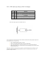
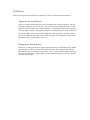
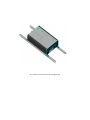
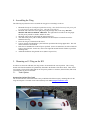
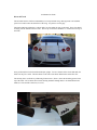
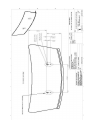
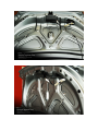
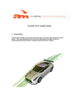
S1 R35 GT-R Install Guide 1. Quick Start Guide Aeromotions recommends professional installation of the S1 Wing. If the wing was professionally installed, here’s what you need to know to use it. The wing has three angles: Braking, cornering, and straightaway. 1. 2. 3. 2. The Braking angle is high downforce and high drag for maximum stopping power. The Cornering angle should be set to provide the level of downforce needed to balance the car at the traction limit in a turn. The correct angle is dependent on car setup, and should be adjusted by holding down the CORNERING button and using the UP and DOWN arrow keys. Straightaway is set for low drag. You can increase this angle if you want more stability at high speed. Tuned for your GT-R The Computational Fluid Dynamic (CFD) model of the GTR, shown below, will let you see how the air flows around the GT-R. It’s worth noting that the air follows the rear window of the car, approaching the wing at a downward angle. This “apparent angle of attack” means the wing “feels” a higher angle of attack than you would measure with a level (which assumes the air is coming straight on). This is why your wing has a maximum stall angle of 7.4 degrees when mounted on the GTR (instead of the 14.2 degrees of the wing by itself). Tuning Cornering Angle This graph gives the maximum downforce as a function of speed for the Nissan GTR at 7.4 degrees The cornering angle should be adjusted based on the front aero on your GTR. The Aeromotions wing features a high performance airfoil. With an Aeromotions wing, small wing angles produce much more downforce than standard wings at the same angle. When tuning on a new car, the goal is to get the rear aero (wing, diffuser, etc) to balance the front aero (splitter, canards, etc). As a rule of thumb, a 30-60mm front splitter should start with 2-3 degrees of wing angle, and increase 1 degree at a time. As the below graph shows, the effect of the wing will increase with the square of speed. Low speed handling is dominated by tires and suspension, high speed handling is dominated by aero. The crossover point is somewhat unique to each car and setup. 3. Wiring Connections on the Dynamic Module Power Cable The Dynamic Module requires 10Amp switched power. +12V should be applied to the red wire. The Black wire is ground. Data Cable ( 3 wire connector) VSS o o o o o The Blue wire connects to the vehicle VSS wire. Connect the VSS wire from the GTR Navigation as described below.. For a stand alone ECU, the output signal should be: A square wave (OC) 0-5V or 0-12V See below for setting pulses per mile The black wire is an extra ground wire, it can be left disconnected or may be used with some standalone ECU’s A sine-wave output from a hall effect sensor will not work. Data Logging o An optional Analog Output Cable is available for purchase from Aeromotions to output the wing angle as an analog voltage from 0-5V. If that cable is being used, the Red wire is the output for the Setting the Vehicle Speed Sensor The Pulses Per Mile (PPM) that the ADAPT Controller reads from the vehicle is programmable in wings sold after March 2013. The PPM only has to be set once, then is stored in the ADAPT Controller. To set the PPM, Power On the ADAPT Controller while depressing the SPEED SET Button. A single LED on the 10 LED Bar display will be illuminated to indicate which PPM is selected as shown in the table below: LED 1 2 3 4 5 PPM 3,600 4,000 8,000 10,000 45,056 VEHICLE CAN Adapter EVO and Corvette GT-R Porsche Use the UP and DOWN arrow keys while depressing the SPEED SET Button to select the PPM for your car. For example, for a GT-R, the 3rd LED would be lit. Powering OFF the ADAPT Controller will return it to normal operation and it will remember which PPM you selected. 2012+ GTR Vehicle Speed Sensor (VSS) CAN Adapter Color Black I/O I Function Ground Red I Power +12V regulated ignition controlled supply Yellow Blue I I CAN High CAN Low Orange O Speed Pulse Output 12V Connect the Orange output wire to the Blue VSS wire The CAN Adapter has built-in diagnostic LEDs to indicate CAN Bus status and speed pulse output to aid the installation process. After power-up: Stage 1: Both LEDs light for approx 1 second Stage 2: Green LED on while the CB-1 listens for CAN Bus data Stage 3: Red LED indicates CAN has been detected. CB-1 now detecting vehicle type Stage 4: Once vehicle type is determined the Green LED should pulse when vehicle is driven. Red LED should stay on. Please note: If LEDs do not follow the above sequence it is still advisable to drive the vehicle to see if a speed pulse signal is still actually being produced by the CB-1. It is possible that some vehicles will perform in a different manner. General Installation Notes The CAN Bus uses two wires for data transmission. One is called CAN_HIGH and the other called CAN_LOW (sometimes marked as CAN+ and CAN- respectively). All connections should be made with an insulated solder joint. Do not cut the CAN Bus wires. IMPORTANT NOTICE: All connections are for guidance only and to the best of our knowledge. We cannot be held responsible for changes made by the vehicle manufacturer. The CAN Bus system is growing in use by American and European vehicle manufacturers. Unfortunately, they do not conform to anyone standard or wiring concept. Colors can vary as well as location and layout of ECU's. In addition, a vehicle can have more than one CAN Bus system, with potentially only one set carrying the speed pulse data. It is also advisable to disconnect the CAN I SCP interface before any diagnostic work is carried out on the vehicle. This will prevent any possible damage to the interface and also allow any diagnostic work to be carried out successfully. 1. Since manufacturers continually change the pin configuration of the plugs, it is advisable to pick up Pos and Neg for powering the interface from an alternative supply, preferably a good ignition controlled regulated supply. A good earth is essential. 2. The CAN Bus interface has such high internal impedance that it cannot affect the vehicle operation. 3. Connect the CAN High and CAN Low wires before powering up the CB1 interface, so removing any possibility of shorting. While the power wires can be extended, it is not advisable to extend the CAN High and Low leads. If there is a need to extend the signal lead (Orange), please ensure that it is run to its destination avoiding being close to equipment that might give off pulses which could be picked up by this wire, such as ignition or heater fans, etc. OBD II Plug 2007-2011 GTR Vehicle Speed Sensor (VSS) The VSS provides the vehicle speed to the computer. The VSS is tapped from the dash behind the navigation console. First remove the center console near the passenger seat. It pulls straight out near the center and slides back near the front. Behind the DVD head unit, there is a WHITE plug with 20+ positions. From the rear of the unit, it would be on the top left corner. From your passenger side view, it’s the closest to you on top. Near the center of the TOP of the plug, is a red power line, right next to that is a VIOLET line. The violet line is the VSS wire. Note, Australian, and British GT-R’s have a light green VSS wire. \ VSS Australian VSS wire, Light Green, in the same location as the USDM VSS. GT-R Power Power can be tapped off an existing 10A switched line, or run as a switched relay from the battery. Tapping into the switched power. There is a 10 amp switched cigarette receptacle toward the back of the center arm rest. This can be tapped to supply the power for the wing. This circuit is already switched and fused. At track speeds, the wing will require all 10 amps, in which case, you should not use the cigarette lighter to power any other accessories. Unplug phone chargers or any additional power draws for track use. The cigarette lighter can be pulled forward through the console in which it is mounted. Doing so will prevent substantial disassembly of the console. The power can be tapped here, and run back through the hole the cigarette lighter came out of. Running power from the battery. The battery is on the right side of the engine compartment. There is a small rubber stopper behind the battery that goes directly into the cabin. Pull the side panel (lower right passenger side, one plastic thumb screw, then pull panel in towards car evenly - it pops out). Behind that and UP is the ECU and wiring harnesses. Looking farther up and toward the front firewall you will see the hole from the removed stopper. 4. The Control Box Mounting The control box should be mounted to the deck lid, as shown bellow. The writing should be facing the correct direction when the deck lid is up. S1 Controller with CF trunk mounting adapter rails 4. Assembling the Wing The following steps describe how to assemble the wing prior to mounting it to the car. 1. 2. 3. 4. 5. 6. 7. 8. Mount the front pivot of each power pod to the S1 wing. Note that the bottom of each power pod is cut at an agle to match either the left or right side of the deck lid. Mount the rear control arm of the right power pod (passenger side) to the wing. DO NOT MOUNT THE LEFT CONTROL ARM YET. The right control arm will set the wing angle. The left power pod will be flexible, and able to rotate. Mount the wing to the deck lid using the instructions below. After both of the power pods are firmly attached to the deck lid, the left control arm will be attached to the wing. Power the wing on, with the deck lid closed. Unscrew the left rod end until the eyelet hole lines up with the black wing support hole. This will ensure both halves are balanced. Insert the rear shoulder bolt in the left power pod half. (In rare circumstances, the left rod end will be above the pivot hole. In this case, unscrew the right rod end until the left end lines up with the mounting hole). Attach the End Plates using the M5 screws (Max Torque 4 N-m). 5. Mounting an S1 Wing on the R35 In order to use the stock GTR tune, the wing needs to be mounted in the correct position. The S1 wing mounts with four M6 studs that are permanently mounted to the bottoms of the Power Pods. These can be cut to length. The electrical cables that run to each power pod have a connector (shown in blue) that needs a clearance hole to pass into the trunk. 5.1 Trunk Options Aeromotions Carbon Fiber Trunk The Aeromotions R35 carbon fiber trunk comes pre-drilled with all the necessary mounting holes for the wing and computer. The trunk can be ordered directly from AMS amsperformance.com/ S2 Mounted on Trunk Nissan OE Trunk The OE trunk must be reinforced substantially to securely hold the wing. Bracing needs to be installed span wise in order to take the downforce of the wing. See pictures on next page. The black aluminum uprights have carbon shells, feet, that adapt the wing to the trunk. These feet should fit snugly into the bottom of the aero tube. The rear tip of each foot should be 5 1/2 inches from rear lip of the trunk. Once positioned, three holes should be drilled per upright. Two are clearance holes for the M6 studs, the third is for the power cable. The three holes are the same as the holes drilled in the carbon fiber feet. The drawing below (available as pdf drawing W-00329-00-1, Sheet 1) shows the mounting pattern in the top of the trunk. The six holes shown in this drawing should be through holes to accommodate the M6 Studs (4 x Ø.25) and the connectors (2 x Ø.63) User Manual: Dynamic Wing S1 1. Dynamic Wing S1 The S1 Dynamic Wings come with a plug and play tune specifically developed for your car. The controller will automatically provide ample downforce in corners, more when you brake, and lower drag on the straightaway. The wing is programmed with angles tuned for your car. Braking Angle o The wing moves to this high downforce, high drag angle during braking. Maneuvering Angle (Low Speed Cornering) o This is the default wing angle. The wing at this position when the car is standing still, or cornering. Increasing or decreasing this angle will change the car’s balance in corners. High Speed Maneuvering Angle (High Speed Cornering) o This angle allows a different maneuvering angle to be set for high speeds. Straightaway Angle o The wing moves to this low drag angle when it detects the car is on a straightaway. Note, each racecar setup is unique. Dynamic Wings are programmed to work with the stock upper surfaces of the car. Any aerodynamic modification to the car, such as roof scoops or vortex generators, can change the airflow and necessitate adjustment to the tune. 3. Pre-Flight Check When the power is turned ON, the wing performs a startup check. The wing will move to each of the programmed angles. Watch to ensure the wing moves smoothly, and freely. The wing will skip this check if the car starts to drive. 4. Basic Controller Operation Track Maps The stock tune is stored in track map 1. Holding down the “Track Map” button and pressing the “UP” or “DOWN” button cycles through ten different maps. The selected map is indicated on the 10 Segment LED by a single lit LED. Track Map “0” (all LED’s flash as a block) locks out the wing at the Cornering angle. The wing will function as a static wing. 5. Advanced Controller Operation Adjusting The Wing Angles The wing angles are set by holding down any of the four “Wing Angle” buttons and adjusting the “UP” and “DOWN” buttons. Cornering Angle Turn the wing on. After the pre flight check, the wing will be in the Cornering angle. Pressing and holding the Cornering angle will allow you to adjust the angle. Note: since this is the default angle, pressing this button will not cause the wing to move. Braking Threshold Holding down the “Braking Threshold” button allows the deceleration value that causes the wing to move to “Braking Angle” to be adjusted using the “Up” and “Down” buttons. The “Braking Threshold” value is displayed on the 10 Segment LED where each lit LED is 1/10th of a G. Acceleration Threshold Holding down the “Acceleration Threshold” button allows the acceleration value that causes the wing to move to the “Straightaway” angle to be adjusted using the “UP” and “DOWN” buttons. The “Acceleration Threshold” value is displayed on the 10 Segment LED where each lit LED is 1/10th of a G. Speed Set Checking the VSS Pulse and Scaling Holding down the “Speed Set” button puts the controller in Speed Setup mode. Speed Set mode is used to check that the controller is getting an accurate speed reading from the Vehicle Speed Sensor (VSS) While holding the Speed Set Button, The 10 segment LED will flash with each pulse from the VSS as the car is driven forward. This is best observed at low speeds. After verifying the pulses at low speed, the 10 Segment LED can be used to verify the accuracy of the scaling. Above 50 mph, the LED’s on the 10 Segment LED will light to indicate the vehicle speed. Each LED represents 10 mph over 50 mph. One lit LED indicates 60mph. Two lit LED’s is 70mph, and 5 lit LED’s would shows 100mph. Setting the Speed Threshold The speed threshold determines when the wing reduces angle for high speed straightaways. To adjust the speed threshold, hold down the “Speed Set” button and the “Straightaway” button and adjust the “Straightaway Speed Threshold” using the “UP” and “DOWN” buttons. The “Straightaway Speed Threshold” will be displayed on the 10 Segment LED as described above: each lit LED represents 10 mph over 50 mph. Show Mode: Hold the down arrow when powering the computer (car) on. 6. Legal Notice PROFESSIONAL INSTALLATION IS HIGHLY RECOMMENDED and products are understood by consumer to be OFF-ROAD USE ONLY upon purchase. RACING IS INHERENTLY DANGEROUS. The consumer assumes responsibility and all liability associated with operating an aeromotions wing upon purchase. CHECK ALL EQUIPMENT before racing. Car setup is unique. The consumer is responsible for ensuring the correct setup, tuning, and working of the Dynamic Wing with their vehicle setup.