1
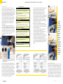
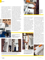
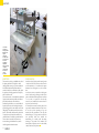
OUR TESTS
The Editor
The Little
genius
50
T
his month we will approach again the subject of
“heavy” stationary equipment testing a 6 function
universal combination machine particularly aimed at
DIY enthusiasts of different experience and
small workshops where production is mainly focused
to non large one offs and made to measure.
Before entering the heart of the test, we think it is
appropriate to supply more general
information which
will support the least
experienced in understanding this specific area of
the machinery offer.
While for many tools used in the workshop the mane
itself often cannot suffice to express the group and
the applications allowed by the tool itself, in the case
of a multifunction combination machine it is
immediately clear. To understand what kind of
machine we are approaching, to the least we
need to ascertain the number and type of
machining achievable, just because other machines
called “combination” are in effect planers/
thicknessers or tenoning/sawing machines. In the
case of machinery performing more than two
functions, planing is always included.
In this case the first useful information comes from
the commercial name of the combination: as in
the case of the Minimax C26, the two numbers
indicate in fact the length of the planing knives
(specifically 26cm). Because knives lengths are
standard (21, 25, 26, 30, 31, 40cm and so on) it will
be quite easy to recognize them, even if preceded
or followed by another number or a letter.
Why this is the figure that’s brought forward amongst
the many available is quite simple: planing is the first
operation to be done on a piece of (solid) wood when
using a universal combined machine, all following
operations will be proportioned to the capacity of the
first one. It would be quite unusual not to find a
250mm tilt able blade on a universal with 40”
knife width, or viceversa expect wide work surfaces or
high power motors on a 21” universal combined
machine. Clarified this aspect, while that dimension
cannot be exhaustive, it is already enough to get a
good idea. This can be further confirmed by other
data, which can be collected from the technical
specs, and will have to be carefully examined to
obtain a more complete image of the specific piece
of equipment. In particular the presence of the CE
branding ensures the machine conforms to the
present safety rules,
6 functions in about one square
metre, offered at an attractive
price ... is all that glitters gold?
the number and specs of the motors confirm the fit or
not to heavy duty machining, while the length of the
carriage together with the size of the squaring frame
will determine the max measures of the panels
that can be sized in full safety.
Once you are in a position to buy a universal
combination it is important to keep in mind
the footprint of the machine, fully equipped or at least
in the configuration we expect will be mostly
used, because the main reasons driving the choice
against single function machines are precisely the
space taken in your workshop and the total
price of more machines. In case these two factors
are not of the essence, we need to point out that
every universal combined hides, amongst its
advantages, some negatives; they are usually related
in the set up times every time a change is needed
from a function to another, times that clearly
become increasingly larger every time you need to
go back to a function previously performed.
Furthermore, as all machines that perform more
than one function, all applications must represent a
compromise, thing that is expected on a lesser
level on a specialized machine, for example,
which can execute a single operation. It is precisely
keeping in mind these aspects that we have
approached the testing of the C26.
n.24 year 2010
51
OUR TESTS
COMBINED UNIVERSAL MACHINE
THE MACHINE
The machine has been delivered on a pallet and
wrapped in thermo folding film, inside which there
was the standard equipment, including user’s manual,
allen keys, knife setting dime, the squaring frame and
fence, the spindle hood and the parallel fence. Also
included a few spare fuses and few components that
due to transportation could not be fitted in the
factory: the squaring frame and various protections.
With the exclusion of the scoring blade and planer’s
cutter, all other cutting tools are not part of the
standard supply and have to be bought separately,
keeping in mind the specs, and installed by the
machine buyer.
In the standard supply you will find the mobile
electrical plug normed IEC309 that will be used to
connect to the electrical panel found on the machine,
while the remaining connections to the main line is
responsibility of the machine owner. The bi-lingual
user manual is well done and with its pictures leads
the user through the various phases of the
installation.
MACHINE FEATURES
PLANER
- Working width: 260 mm
- Cutter block diameter (mm)/n. standard knives: 62/2
- Standard HSS blades Size: 260x25x3 mm
-Planer max removal: 3 mm
- Total length of surfacer table: 1040 mm
- Dimensions of Thicknesser table: 260x450 mm
- Thickness feed speed: 6 m/min
- Min. ÷ max. Working thickness: 3 ÷ 200 mm
CIRCULAR SAW
- Saw-spindle moulder table dimensions: 1024x224 mm
- Blade tilt: 90° ÷ 45°
- Maximum blade diameter: 250 mm
- Max blade depth from the table at 90°/45°: 80/64 mm
-Squaring capacity: 1300 mm
-Parallel fence cutting width: 500 mm
SPINDLE MOULDER
- Effective length of the spindle: 75 mm
- Spindle rotation speed (a 50 Hz): 5000/7500 giri/min
- Maximum diameter profiling tool: 160 mm
- Max dia. tool lowered under table at 90°: 150 mm
- Spindle shaft available in following diameters: 30 mm, 1 1/4"
OTHER TECHNICAL CHARACTERISTICS
- Single-Phase Motors (S1) 1,5 kW 2 hP 50 hz
- Extraction hood outlet diameter: 120 mm
- Weight 240 kg
STANDARD SUPPLY
- Flush sliding alluminium wagon 1140x201 mm
- Adjustable spindle moulder fence
- Preset for morticer
The electrical control panel with the two switches on the
left from which you control all the functions of this
combination machine.
Captured by the desire to start up the machine and
test it as soon as possible, the assembly of the various
components might appear as annoyance, but we
think instead it is an excellent way to gain confidence
and start knowing the new machine.Having a foot
print of 1190 x 935 (without squaring frame and
morticer) the machine looks compact and well built.
The cast iron tables are well fixed and levelled with
each other and contribute to the solid look offered
by this small combined universal machine.
52
After having carefully cleaned the table tops from the
protective oil to avoid rusting and after having
installed a circular saw (we have opted for a
multifunction 60 tooth blade) we have carefully
looked at the electrical control panel. This is
positioned just below the circular saw setting handles
in an easy to reach position when using the saw blade
and spindle functions. For operations involving
planing, which are performed from the opposite side
of the machine, an emergency stop button is in close
proximity of the in feed table.
Returning to the main electrical control panel, it
incorporates a magneto-thermal two position switch, a
five position selector, the plug to connect the main
and an emergency button.
The use of the controls is intuitive; first select the
working group on the 5 position selector
(saw/planer/spindle/all off/unlock spindle brake)
then start the machine by selecting on the
thermo-magnetic switch position 1. The full stop of
all groups can be archived via the thermo-magnetic
switch or the two emergency buttons, the one
mounted on the front control panel being in an easily
accessible position during thickness operations, while
a bit more complicated while using the saw or the
spindle.
The blade tilts
through the
upper three
lobes knobs
group. The most
external moves
the blade, and
the coaxial
innermost locks
the position.
Given the
proximity to the
post that
supports the
cart, the
maneuvers are
not very easy
just as dial
reading.
The lower knob
instead controls
the rise/ fall of
the blade; it is
reachable more
easily but, given
its small
diameter, just
like the higher
one, requires a
certain effort
from the user to
be operated.
THE SAW GROUP
Positioned on the left side in respect of the control
panel, it shares the working table with the spindle and
allows for the use of a 250mm blade with 30mm bore.
The tool is protected by the extraction hood,
blocked with a lever above the riving knife. To Install
or substitute the blade it is necessary to remove the
access door placed on the left side and block the shaft
with the supplied pin. To remove or position the
saw blade on its shaft is not a effortless job as it
requires the pushing away of the extraction hood but,
n.24 year 2010
53
OUR TESTS
once learned, the up and down movements of the
blade and those for its inclination are performed via
one compass mechanism and one rack and pinion,
activated by two 3 faced rotary handle.
The diameter of these is a bit small to avoid reciprocal
interference hence it is necessary to be fairly strong
to spin them and move the blade in both directions.
The inclination reached can be checked by an index
that runs on the graduated arch behind the handle.
Like all solutions of this kind, the reading of the angle
value is affected by parallax, but the positioning of the
blade (verifiedin comparison to the stops at 45 ° and
90°) was absolutely correct, either by reference to the
wagon or by referring to the table on the right of the
blade. The carriage is made of aluminium extrusion
and runs on the rails of the frame (also alluminium)
using a polycarbonate ball slide. Not including the
pushing table, it measures 1140x200 mm and offers a
squaring capacity of 1300 mm. Can be blocked flush
with the strut via the guillotine movement of a plate,
pivoted on its mast, which links the two structures.
The squaring frame uses the classic flag support
which, when not in use, can be folded back on itself
to avoid hampering the movement around the
machine. The fixing of the frame to take a carriage is a
simple and functional device based on a steel plate on
which are screwed two rods.
The plate should be inserted in the side slot of the
carriage to support the inner side of the squaring
frame. On this are also two holes that hug the rod,
while the opposite side rests on the pin of the flag.
Externally the two slots, the chassis has two plastic
shoes that fit snugly inside the hollow side of the
carriage. Can be adjusted to align the upper edge of
the frame with that of the carriage. Once inserted the
shoes in the slot, tightening the two knobs links
permanently the frame to the carriage.
The tightening of the
squaring frame is via
the two knobs of the
support inserted in
the hollow of the
carriage.
The assembly does not take more than a few minutes
as it is fairly easy to do and can be accomplished
without the help a second person.
The installation of the squaring fence is as simple and
can be done on both sides of the frame perpendicular
to the wagon. The fence can be oriented between 90
and 45 ° and its 90 ° stops are adjustable. The locking
of the panels or work pieces on the carriage or on the
squaring frame is facilitated by the presence of a
mobile clamp that fits within the upper slot of the pre
buon a.The movement of the carriage is proceeding
smoothly and without jamming even with the
squaring frame installed, to the benefit of the finish of
the cut which is always good.
The blade tilt control revealed a perfect match of
the lines 45 and 90 °.
The visualization of the angular value is influenced
by the parallax and the size of the index.
The wagon carriage, removed to highlight the sliding mechanism on the trellis, consists of a polycarbonate ball slide.
Two felts placed at the beginning and the end of the slide keeps the balls clean. The mobile guide located on the inner side of
the truss is registered at the factory to provide a movement of the carriage properly parallel to the blade.
54
The last component to be analyzed is the guide for
parallel cuts; also made from extruded aluminium, it
slips on a support that slides and locks, with an
eccentric lever, on a 'rod with a rectangular section
fixed to the cast iron surface of the machine.
The rod incorporates a line graph whose values can be
read through an open window on the support of the
guide. The line graph is not adjustable, but the
fastening of the rod to the surface allows its
adjustment to serve as a micro setting. The guide is
also used for working the planer and is therefore
longer than necessary when used on the saw. The end
opposite the point of locking on the support is
influenced by this factor and the elasticity of the guide
itself, when the guide is resting entirely on the surface,
and tends to move under pressure, but this is not a
problem because the guide can be moved
longitudinally with respect to its support, allowing the
withdrawal when machining closer to the blade. The
saw unit includes dust extraction on two fronts, over
the blade with the guard and under the machine
through an outlet. The system is well-thought and
allows almost complete extraction of dust. To test the
machine on the parallel cuts we have used blocks of
varying thickness, the combination blade / engine
proved adequate, leaving a finish free of burns and
generally good on all surfaces.
The parallel fence splits its functionality between the saw
and planer; when using with the saw it offers the lowest
stroke. On it, is locked a metal protection that serves to
cover the drum of the planer when it is not used at full
width. In the right picture, the window on the graphed line
allows you to set the distance from the blade.
n.24 year 2010
55
OUR TESTS
For use with the surface planer under the entry table
are provided the emergency button, a lever to adjust
the stock removal and one that prevents the first to
move accidentally.
The unusual alignment procedure of the knives
involves the use of a template fastened to the outfeed
table of the planer.
The parallel fence is located to square the two sides of a joist
at 90 degrees. The protective bridge is height adjustable to
ensure the passage of the piece under the cover and can be
tilted in the direction of the electrical cabinet not to obstruct
the working of the saw.
56
THE PLANER
As we mentioned at the beginning, it uses two 260mm
knives, fixed on the drum through the customary gibs
system. In a less conventional way, the knives’ register
template consists of a steel flange that is fixed on the
exit table with two bolts to provide an upper end to
the knife during the setting. The template incorporates
a steel pin that enters a hole in the drum to prevent it
from turning while you make the adjustment.
The fact that the knives are not registered with
reference to the drum, assumes by the producing
company great confidence in the finished product, in
the goodness of parallelism between the out feed table
of the surfacing planer to the one of the thickness
planer. This does not alter the fact that the system has
proven practical and has allowed a good registering of
the knives in a short time.
Both the in feed table as the output one can still be
registered, if necessary, adding shims on the steel slides
along which they run.
The transversal movement of the in feed table allows
you to increase or decrease the depth of cut of the
planer. The adjustment is achieved moving up or down
a lever on the left side of the in feed table and can be
checked paring the integral index with the lever with
the micrometric plate placed on the sump of the. The
cutter holder drum has a protection-type bridge,
adjustable height and width, which performs its job
well without being intrusive.
The protection can be unlocked and flipped out of the
way not to interfere when working with the saw.
machine.
The parallel fence has two installation options when
operating as a surfacer, 90 ° or 45 °, non adjustable
unless if fitting spacers between the extrusion and its
support.
The two values are, however, proved correct in the
trial conducted on the sample test.
Regardless of the mounting position, the guide offers
an excellent support to pieces always exposing its
maximum area. The flexing that we had mentioned
before does not affect processing, because near to the
drum the guide offers excellent rigidity. When surface
planing the chip extraction works from below and the
120 mm connection is under the exit table; its body
was slightly deformed and invaded the trajectory of
knives. After a small adjustment to restore its shape,
the cap has proved efficient managing to keep the
table and the area below free from chips.
The surface planer has produced flat surfaces with a
good finish and guide has made it possible to square
correctly at 90* pieces of different proportions.
The transition to the thicknessing operation starts by
removing the fence, necessary to enable the flipping of
the out feed table.
This is to be released from the external side by rotating
a cam lever located under the table; the lever is a bit
'short and you have to bend down to see it. The dust
removal hood is overturned after pressing a sprung
switch that keeps it over the drum and on the in feed
table.
The thicknessing table is suspended on a central piston
driven upward or downward by the rotation of the
wheel on the right side of the electrical cabinet. The
removal is set referencing the indicator attached to the
table which passes over a micrometric plate of good
quality and very clear. The drive unit based on one
entry roll (preceded by ant kickback finger protection)
and one on the out feed is set in motion by acting on a
lever on the left of the table. The 6 m / min feed
seem a good compromise allowing a good finish of the
planed faces. When checked the planed surface was
always parallel to the reference one.
The transition to
thicknessing only
requires tilting over
of the outfeed table.
The removal is set
by setting the index
fixed to the table
against the line
graph. On the left of
the ruler you see
the lever for the
inclusion of the
feeder and the
button for
emergency stop.
The planed surfaces are well finished with the exception of a
slight pixelation at the bottom of the pieces, which can be
avoided by supporting the workpiece at the time of the
release of the input feeder. Underneath, the command to
unlock/lock the output table uses a short lever not very easy
to reach.
n.24 year 2010
57
OUR TESTS
The tool
aperture.
At the center,
above the motor,
the speed change
system.
On the left, the rod
for mechanical
locking of the
spindle, inserted in
the relating slot.
The system hood/stop
guides is complete with
security systems fro
workpiece holding and
shielding.
The wheel for the
vertical
movement of the
tool is positioned
on the left side of
machine.
The control system of the
outfeed guide
for system offset.
THE SHAPER
The opening containing the spindle is located in a
classic position, on the saw table, in front of the
circular blade. The impression, when opening the
concentric rings closure, is related to the depth
This, at first sight, is actually limited. In effect, then
we have verified, it is sufficient to contain a 40 mm
cutter block, which after all can be considered the
most suitable tool for this category of machinery.
The vertical movement system of the spindle is
smooth and easy access is provided disassembling first
the squaring frame, anyway not in the normal
profiling jobs.
58
Similarly, also the setting during tenoning operationss
is easy, provided you use the special table, but would
be slower when using the cross arm and support for
squaring frame. The installation/replacement of the
tool is made subject to mechanical blockage of the
spindle, using the same cylindrical wand used to move
the blade. The spindle is accessed after opening the
front door.
The tool locks to the spindle with the classic variable
rings system, cover with safety plug and bolt. The
system of electric safety brake release through
multi-position switch allows manual rotation of the
tool for operations setting. The changing of speed
rotation is always achieved accessing the internal
compartment, through moving the position of the belt
with respect to the pulleys, with a standard system
lock/unlock lever.
The hood with the stops and slide guides is of the
traditional type, free to move with two threaded studs
and slotted guides, with rear extraction outlet.
The input guide is fixed, while the second also has the
offset adjusting for the machining of "all wood", not
present in all machines in this category. The hood has
a folding cover which also serves as a support for the.
protective systems to hold components and to
shield.The dimensions are well proportioned to the
operating capacity of the machine, and the setting of
both hood and piece holding positions is simple and
fast. A note of credit resulted from using the machine
goes to the brake system which is able to stop the
rotation of the cutter in about two seconds, helping to
make all work safer. The shaper was tested with
a cutter head with interchangeable knives, with new,
sharp blades, on two strips of soft and hard wood.
The process was easy and did not show any obvious
problems.
n.24 year 2010
59
OUR TESTS
The morticer
accessory in
working position.
Beneath to the
right the
orthogonal
movement lever,
to the left on top
the one for
longitudinal
adjustment.
Above to the right
workpiece
pressor, below
the wheel for
vertical
movement.
MORTICER
CONCLUSIONS
The morticer is a classic one, installable to the side of
the planer spindle shaft. The spindle is a radial
clamping double screw type, for 16 mm attachment
bits with left handed rotation. Disassembly and
assembly of the bits is a sufficiently easy task, despite
the presence of the bridge protection of the planer,
which is sufficient to lift.
The morticer consists of a movable table, adjustable in
height by handle, with the possibility of combined
horizontal movement in various directions.
Dedicated ring locks allow you to set the width and
depth of the mortice, and a vertical pin hosting the
piece holding pressor (the same which is used on the
sliding table). The extraction outlet is located at the
bottom. The assembly and disassembly, achieved via
3-shaped slots and as many bolts attached to the
structural frame of the machine, is practical and fast.
The test that we have made has shown an easy
movement through the dedicated levers, and an
excellent general mechanical structure.
Overall, the Genius C26 has provided entirely positive
evidence and feel. What becomes evident from the
overall examination is of a machine with compact
dimensions but well designed, very solid, in which
there
has been no economy on material as often happens
others of similar category. Bearing in mind that the
spaces in which this machine might be used could also
be very small, it is positive the fact that chip
conveyors, even combined with a vacuum cleaner of
low power, have done their job.
It is clear that the measures the surface planer, of the
wagon and the maximum dimensions of the tools to
be used do not allow processing of large size
materials, but still proportionate to the range this
machine belongs to, as a logic wants. In contrast, the
tests performed, which have included the
manufacturing of an artifact, really then taking
advantage of the potential of the machine, have
shown qualities of precision, ease of use and versatility
entirely satisfactory in all processes.
60