1
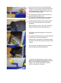
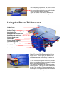
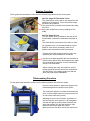
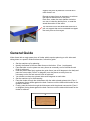
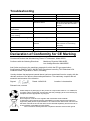
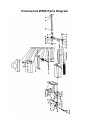
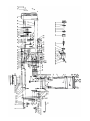
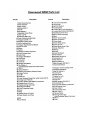
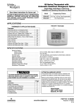
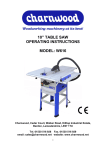
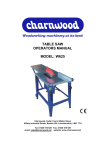
8” x 5” PLANER THICKNESSER OWNERS MANUAL MODEL: W588 Charnwood, Cedar Court, Walker Road, Hilltop Industrial Estate, Bardon, Leicestershire, LE67 1TU Tel. 01530 516 926 Fax. 01530 516 929 email: [email protected] website: www.charnwood.net GENERAL SAFETY RULES WARNING: Do not attempt to operate the machine until you have read thoroughly and understood completely all instructions, rules, etc. contained in this manual. Failure to comply may result in accidents involving fire, electric shock, or serious personal injury. Keep this owner's manual and review frequently for continuous safe operation. 1. Know your machine. For your own safety, read the owner's manual carefully. Learn its application and limitations, as well as specific potential hazards pertinent to this machine. 2. Make sure all tools are properly earthed. 3. Keep guards in place and in working order. If a guard must be removed for maintenance or cleaning, make sure it is properly replaced before using the machine again. 4. Remove adjusting keys and spanners. Form a habit of checking to see that all keys and adjusting spanners are removed from the machine before switched it on. 5. Keep your work area clean. Cluttered areas and workbenches increase the chance of an accident.' 6. Do not use in dangerous environments. Do not use power tools in damp or wet locations, or expose them to rain. Keep work areas well illuminated. 7. Keep children away. All visitors should be kept a safe distance from the work area. 8. Make workshop childproof. Use padlocks, master switches and remove starter keys. 9. Do not force the machine. It will do the job better and be safer at the rate for which it is designed. 10. Use the right tools. Do not force the machine or attachments to do a job for which they are not designed. Contact the manufacturer or distributor if there is any question about the machine's suitability for a particular task. 11. Wear proper apparel. Avoid loose clothing, gloves, ties, rings, bracelets, and jewellery which could get caught in moving parts. Non-slip footwear is recommended. Wear protective hair covering to contain long hair. 12. Always use safety glasses. Normal spectacles only have impact resistant lenses. They are not safety glasses. 13. Do not over-reach. Keep proper footing and balance at all times. 14. Maintain the machine in good condition. Keep the machine clean for best and safest performance. Follow instructions for lubrication and changing accessories. 15. Disconnect the machine from power source before servicing and when changing the blade. 16. Never leave the machine running unattended. Turn the power off. Do not leave the machine until it comes to a complete stop. 17. Do not use any power tools while under the effects of drugs, alcohol or medication. 18. Always wear a face or dust mask if operation creates a lot of dust and/or chips. Always operate the tool in a well ventilated area and provide for proper dust removal. Use a suitable dust extractor. ADDITIONAL RULES FOR PLANER/THICKNESSERS 1. This machine is designed for use with wood. Attempting to plane or thickness any other materials will result in damage to the machine, potential fire risk and/or health hazards. 2. The machine is designed for indoor use only. 3. Connection to a suitable dust extraction system is highly recommended. If you must use the machine on its own, you will need to stop it, unplug it from the mains and thoroughly clean it at regular intervals. Continuing to use the machine when it is clogged with sha 4. vings will result in damage to it, potential fire risk and/or health hazards. 5. The machine should be bolted to a bench or suitable stand. 6. Always hold the work firmly on to the table, using the push pads provided. 7. Never use the planer/thicknesser with the guard and/or dust hood removed. 8. If planing or thicknessing a long piece of timber, provide additional support at the same height as the table. 9. Switch the machine off and unplug it before removing any debris. 10. Be aware of the possibility of kickback. 11. Do not modify this machine in any way or use it or anything other than its designated purpose. Neither the manufacturer nor the suppliers will be liable for any damage or injury caused by incorrect assembly, operation or electrical connection of this machine. Risk of Injury! Never reach into a running cutterblock Wear Eye Protection Wear Ear Protection Rating Description Hobby: Suitable for Weekend DIY'ers and woodworking enthusiasts. Generally lighter weight machines with lower power ratings and smaller tooling capacities. Typically only ever used by one person for short periods of time or longer periods of time infrequently. Machinery should be well maintained in a clean, dry environment such as a home workshop, garage or timber shed. Expected maximum use of 100 hours annually. Please Note: Using a product in excess of its rating will void the manufacturer’s free warranty. Charnwood W588 Specification Voltage and frequency Motor (induction) Planer width Maximum planing cut Work Table Table height Fence tilt Max thicknessing cut Max thicknessing capacity Feed speed Number of blades Cutter block rotation Dimensions (WxDxH) Weight Rating Warranty 240V at 50hz. 1500w (2hp) 200 mm 3 mm 740 mm x 210 mm 360 mm 0 to 45° 2mm 5 to 125mm 8 m/mim 2 8,000 rpm 790mm x 420mm x 470mm 28kg Hobby 1 Year Unpacking Open the top of the carton, invert it, ensuring that all four flaps are to the outside and lift the carton off the packaging material. Separate the polyfoam shells, carefully unpack all of the contents and lift the machine onto a bench. Lay out the parts and familiarise yourself with them. Read the manual. Please do not dispose of the packaging until you have fully assembled and tested the machine. In the unlikely event there is a fault, you will need to re-use the packaging. Assembly Remove the protective paper from the aluminium table and clean with a degreaser, such as WD-40 Attach the four feet to the underside of the planer/thicknesser, using the cap head screws and washers provided. Place the machine on its feet and locate the two tapped holes on the rear edge of the table Position the shallow-tee shaped piece of metal so that the holes line up with those in the table edge. Fit the fence to the table using the two long cap head bolts and washers provided. These protrusions are located on the front edge of the out-feed table (left hand), with the machine facing you. You may need to tighten this nut but do not overdo it. Firm finger tightness is sufficient. Slide the hole at the end of the bridge guard support arm over the pivot shaft and secure the guard by screwing the large yellow knob onto the threaded spindle. This knob is used to lock the arm at the desired angle. The bridge guard slides sideways and can be locked in place with this knob. The angle of the bridge guard can be adjusted with the yellow knob on the side of the arm. This guard and extraction outlet must be fitted onto the thicknessing table during planning operations. Before putting it in place, take note of the three plastic feet and the protruding bolt and nut. Ensure the thicknessing table is wound all the way down. The guard should be inserted so that the bolt fits into this hole in the thicknessing bed. Please Note: If the guard is not located correctly, an interlock switch will prevent the machine from running. Once inserted, the guard should be secured in place by raising the thicknessing bed. To raise the thicknessing bed insert the crank handle into the recess to the side of the outfeed table. Turn clockwise to raise the bed, an audible ‘click’ can be heard as the interlock switch is activated by the guard. For thicknessing operations, the guard is fixed on top of the tables, as show. It is secured by screwing the two yellow knobs into two threaded holes in the table. Again, an audible ‘click’ can be heard as the interlock switch is activated by the guard. Using the Planer Thicknesser Guide Fence Outfeed Table Thicknessing Bed Height Adjuster Arm Angle Lock Bridge Guard Position Lock Bridge Guard angle Lock Planing Depth Scale Infeed Table Planing Depth Adjuster Thicknessing Scale Thicknessing Bed Support On / Off Switch Adjustable Feet Starting And Stopping Slide the red section upwards and then lift the hinged cover. This will give you access to the green start and red stop buttons. Pressing the red section of the cover will stop the machine. To turn on, press the green button. Wait for the knives to reach their maximum speed of rotation before commencing with the cut. The machine is fitted with an NVR (No Voltage Release) switch. This type of switch is designed so that if the machine is disconnected from the mains whilst running and then reconnected, the motor will not automatically restart. Planing Function Fit the guard and extraction outlet onto the thicknessing table and lock it into place. Set The Angle Of The Guide Fence The guide fence can be set to any angle from 90 degrees to 45 degrees. There are pre-set stops for those two positions. The guide fence is locked and unlocked by using this lever. Any other angle can be set by reading off the scale. Set The Depth Of Cut Turn the yellow knob, located on the end of the infeed table, clockwise to decrease the depth of cut. The scale shows increments from 0mm to 3mm. As a general rule, it is recommended to set the depth at 1mm and if necessary make 2 or 3 passes until the desired result is achieved. Position the bridge guard so that it covers any exposed part of the cutterblock as shown. Use the push pads supplied with the machine to hold the work piece firmly down against the table and to feed the work piece over the cutterblock onto the out-feed table. When working with very thin material, set the bridge guard all the way across the cutterblock. Set the height of the bridge guard, so that the work piece can pass underneath. Thicknessing Function Fit the guard and extraction outlet onto the planning tables and secure in place. Use the crank handle to adjust the height of the thicknessing bed to match the work piece. The maximum depth of cut when thicknessing is 2mm. A feed height restrictor bar prevents a cut of more than 2mm being made. Standing in front of the machine, as shown on the left, hold the work piece so it is flat against the bed and gently push forward. Release the work piece when you will feel the drive roller take hold and feed it past the cutters. Move around to the other end of the machine to support the piece by hand as a second drive roller feeds it out. Repeat as many times as necessary to achieve the required dimensions of the piece. Each time, rotate the crank handle clockwise one turn to raise the bed by 2mm, or read the actual dimension off the scale. The out-feed end of the thicknesser bed has a pull out support that can be extended to support the work piece as it emerges. General Guide When faced with a rough sawn piece of timber which requires planning on all 4 sides and taking down to a specific finished dimension, follow this guide: Set the machine up for planning. Identify the flattest of the two wider faces on the timber. (Face 1 on diagram) Pass that side over the planer as many times as necessary until a flat and smooth finish is achieved. Hold the planed side firmly against the guide fence (set at 90 degrees to the bed) and pass the narrow side (Face 2 on diagram) over the planer as many times as necessary until a flat and smooth finish is achieved. You should now have two planed sides at 90 degrees to each other. Set the machine up for thicknessing. Pass the timber through the thicknesser with the wider already planed side (Face 1 on diagram) facing down against the bed. Continue until the desired thickness for the timber is reached. Finally, pass the timber through the thicknesser with the planed narrow side (Face 2 on diagram) facing down against the bed. Continue until the desired thickness for the timber is reached. 3 2 4 1 Knife Removal and Replacement Out-feed table In-feed table Locking bar bolts Locking bar Knife Cutter block Using the 8mm spanner provided, turn the bolts clockwise so that you screw them into the locking bar. When you have done this with all 6 of them, you may lift out the locking bar and knife. Be aware that there are two small springs underneath the knife. Remove it slowly so that you do not lose these. Locking bar There are two pins in the back of the locking bar which engage with the slots in the blade. Blade slot The springs are used to lift the knife as part of the knife setting process. Fit the replacement knife, by locating it onto the pins on the back of the locking bar. Ensure the two springs are in place. Place the blade setting gauge on the out-feed table with the curved section sitting over the blade and cutter block. Press down until the setting gauge sits flat on the table. In this way the blade will be set at the correct height, being pushed up against the gauge by the springs. Tighten the locking bar, starting with the two outer bolts, then the inner bolts. Ensure it is firmly locked in place. Repeat these steps for the second knife. Check that the blades do not foul the edge of the table. Troubleshooting Problem Machine does not start Cause Blown Fuse Loose switch terminal Faulty switch Guard not fitted Only starts when Green button is held down Machine runs intermittently Motor running but cutterblock is not rotating Motor slows down during the cut Faulty switch Remedy Replace Fuse Inspect back of switch Replace switch Re-fit the plastic guard ensuring it connects with the interlock switch Replace switch Worn carbon brushes in motor Broken or stretched drive belt Replace motor brushes Replace drive belt Depth of cut is too great Take a smaller cut Dust & Chip collector hood is blocked Clear the blockage and ensure the extractor is functioning correctly Replace or sharpen knives Reset the height of the knives Excess Vibration Planing knives are blunt Planing knives out of balance Declaration of Conformity for CE Marking Charnwood Declare that Woodworking Planer & Thicknesser, Model W583 Conforms with the following Directives: Machinery Directive 2006/42/EC Low Voltage Directive 2006/95/EC And further conforms to the machinery example for which the EC type examination Certificate No. BM 50174252, AN 50174251 have been issued by TUV Rheinland LGA Products GmbH, Tillystrasse 2, 90431, Nurnberg. I hereby declare that equipment named above has been tested and found to comply with the relevant sections of the above referenced specifications. The machinery complies with all essential requirements of the directive. Signed: Dated: 14/04/2010 Location: Leicestershire Richard Cook, Director Please dispose of packaging for the product in a responsible manner. It is suitable for recycling. Help to protect the environment, take the packaging to the local amenity tip and place into the appropriate recycling bin. Only for EU countries Do not dispose of electric tools together with household waste material! In observance of European Directive 2002/96/EC on waste electrical and electronic equipment (EEE) and its implementation in accordance with national law, electric tools that have reached the end of their life must be collected separately and returned to an environmentally compatible recycling facility. Your local refuse amenity will have a separate collection area for EEE goods Charnwood W588 Parts Diagram Charnwood, Cedar Court, Walker Road, Hilltop Industrial Estate, Bardon, Leicestershire, LE67 1TU Tel. 01530 516 926 Fax. 01530 516 929 email: [email protected] website: www.charnwood.net