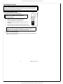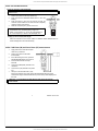
1
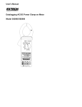
Pinzas analizadoras de potencia 382075 EXTECH manual ingles www.viaindustrial.com User's Guide 2000A True RMS 3-Phase Clamp Power Analyzer Model 382075 Pinzas analizadoras de potencia 382075 EXTECH manual ingles www.viaindustrial.com Pinzas analizadoras de potencia 382075 EXTECH manual ingles www.viaindustrial.com Pinzas analizadoras de potencia 382075 EXTECH manual ingles www.viaindustrial.com Pinzas analizadoras de potencia 382075 EXTECH manual ingles www.viaindustrial.com Table of Contents Safety 4 Meter Functional Description 5 Operating Instructions 6 AC/DC Voltage Measurements 6 AC/DC Current Measurements 7 AC/DC 12W Power (W) and Power Factor (PF) measurements 7 AC/DC 12W Apparent/Reactive Power Measurements (KVA+KVAR) 8 Phase Angle Measurements 8 3 Balanced Power Measurements 9 33W Unbalanced Power Measurements 10 34W Unbalanced Power Measurements 11 13W Power Measurement 13 Calculation of 34W Power Factor (PF) 14 Improving the Power Factor of a 34W Power System 14 Improving the Power Factor of a 3 Balanced Power System 14 Improving Power Factor of a 12W Power System 14 Phase Sequence Indication 15 Recording Data 15 Recalling Data from Memory 15 Specifications 16 Battery Replacement 18 3 382075 V2.2V 9/10 Pinzas analizadoras de potencia 382075 EXTECH manual ingles www.viaindustrial.com Pinzas analizadoras de potencia 382075 EXTECH manual ingles www.viaindustrial.com Safety International Safety Symbols This symbol, adjacent to another symbol or terminal, indicates the user must refer to the manual for further information. This symbol, adjacent to a terminal, indicates that, under normal use, hazardous voltages may be present Double insulation Safety Notes Do not exceed the maximum allowable input range of any function. Set the function switch OFF when the meter is not in use. Remove the battery if meter is to be stored for longer than 60 days. Warnings Set function switch to the appropriate position before measuring. Do not measure current on a circuit whose voltage exceeds 600V. When changing ranges always disconnect the test leads from the circuit under test. Cautions Improper use of this meter can cause damage, shock, injury or death. Read and understand this user manual before operating the meter. Always remove the test leads before replacing the battery. Inspect the condition of the test leads and the meter itself for any damage before operating the meter. Repair or replace any damage before use. Use great care when making measurements if the voltages are greater than 25VAC rms or 35VDC. These voltages are considered a shock hazard. Voltage checks on electrical outlets can be difficult and misleading because of the uncertainty of connection to the recessed electrical contacts. Other means should be used to ensure that the terminals are not "live". If the equipment is used in a manner not specified by the manufacturer, the protection provided by the equipment may be impaired. Function Input Protection A AC, A DC 3000A DC/AC V AC 750V AC V DC, 1000V DC 4 382075 V2.2V 9/10 Pinzas analizadoras de potencia 382075 EXTECH manual ingles www.viaindustrial.com Pinzas analizadoras de potencia 382075 EXTECH manual ingles www.viaindustrial.com Meter Functional Description 1. Transformer Jaw Used to sense current signal. To measure current or power, the conductor under test must be fully enclosed by the jaw. 2. Transformer Trigger Press to open the jaw. 3. Data Hold Button Press to freeze most recent reading on the LCD. Press again to release. 4. Function Select and On/Off Switch Select desired function, such as KW, V, A, KVA, or 3. 5. LCD Display 4-digit (9999 count) display with function symbols, units, decimal point, low battery icon, and zero indication. 6. Units Symbols Once a function is selected, the corresponding unit (KW, V, A, Phase, KVA, or 3) will be displayed. 7. 33W and 34W Select Button If the 3 system is not a balanced system, users can press this button to select 33W, 34W or a balanced system. Once the button is pressed, the LCD displays 33W or 34W depending on the function selected. 8. Read/Next Button When the rotary switch is set to the 3 function, the READ/NEXT button is used as a NEXT button. In the 3 balanced mode, pressing the NEXT button will display W+PF, KVA+KVAR, or V+A data. In the 33W mode, pressing the NEXT button stores the measured values WRS(L1L2) and WTS(L3L2). After two values are measured and stored, the meter adds the two values, displays the result with the symbol WRST to represent W33W . To start another W33W measurement, press the NEXT button again. In the 34W system mode, press the NEXT button to store the measured values WR(L1), WS(L2) and WT(L3). After three values are measured and stored, the meter adds the three values, displays the result with the symbol WRST to represent W34W . To start another W 34W measurement, press the NEXT button again. If the rotary switch is not set to the 3 function, the READ/NEXT button is used as a READ button. Stored data in memory (saved by pressing the REC button) can be read by pressing READ. 9. & 10. V and COM Input Terminals Used as positive and negative (common) inputs for voltage measurements. 11. DC A/W ZERO button Press this button once to zero the Amp or Watt display. While the meter is zeroing, the word ZERO appears the LCD. 12. REC button Press the REC button to store up to 4 data points in meter memory. 5 382075 V2.2V 9/10 Pinzas analizadoras de potencia 382075 EXTECH manual ingles www.viaindustrial.com Pinzas analizadoras de potencia 382075 EXTECH manual ingles www.viaindustrial.com Operating Instructions NOTE: Ensure that the jaws are clear of any conductors before applying power to the meter. The meter performs an auto zero upon power-up to null any residual magnetism. If this is done with a conductor inside the jaw area, the auto zero function will cause subsequent measurements to be inaccurate. AC/DC Voltage Measurements Voltage (V) and Frequency (Hz) Dual Display WARNING: Maximum input voltages: 1000VDC and 750VAC. Do not attempt to measure voltage that exceeds these limits. 1. 2. Set the rotary switch to the Voltage position (V). Insert the test leads into the input terminals. 3. Connect the test leads in PARALLEL with the circuit to be measured. The power clamp will automatically select the proper range. Read the voltage and Frequency values displayed on the LCD. 4. 5. NOTE: The sensitivity for voltage/frequency measurements is 1V, and the frequency range is 10 - 400Hz. If the frequency is < 10 Hz, the LCD will indicate 0 Hz. If the frequency is > 400 Hz, LCD will show OL. Voltage(V) / Current (A) Dual Display Follow the instructions in the section entitled "3 Balanced Power Measurements" to monitor V and A simultaneously. 6 382075 V2.2V 9/10 Pinzas analizadoras de potencia 382075 EXTECH manual ingles www.viaindustrial.com Pinzas analizadoras de potencia 382075 EXTECH manual ingles www.viaindustrial.com AC/DC Current Measurements Current (A) + Frequency (Hz) Dual Display WARNING: Make sure that test leads are disconnected from the meter during current measurements. 1. 2. 3. 4. Set the rotary switch to the Amps position (A). Push and hold the DCA/DCW ZERO button to zero the reading. Press the trigger to open the jaw and fully enclose the conductor to be measured. The Jaws must be completely closed to make a measurement. Read the current/frequency values on the LCD. NOTE: The sensitivity for current/frequency measurement is 5A, and the frequency range is 10 400Hz. If the frequency is < 10 Hz, the LCD will display 0 Hz. If the frequency is > 400 Hz, LCD will display "OL". Voltage (V) and Current (A) Dual Display Follow the instructions in the section entitled "3 Balanced Power Measurements" to monitor Voltage and Current simultaneously. AC/DC 12W Power (W) and Power Factor (PF) measurements 1. 2. 3. 4. 5. 6. 7. Apply power to the meter with the jaws clear of any conductors. Set the rotary switch to the Watts function (KW). If the watt reading is not zero, press the DCA/DCW ZERO button once to zero it. Insert the test leads into the input terminals. Connect the COM (black) terminal to the neutral line. Connect the V (red) terminal to the power line. Clamp on to the line where the V (red) terminal is connected. The power clamp will automatically select the proper measurement range. Read the Watt and PF (Power Factor) values displayed on the LCD. NOTE: The "+" sign printed on jaw must face the power source for accurate measurements. 7 382075 V2.2V 9/10 Pinzas analizadoras de potencia 382075 EXTECH manual ingles www.viaindustrial.com Pinzas analizadoras de potencia 382075 EXTECH manual ingles www.viaindustrial.com AC/DC 12W Apparent/Reactive Power Measurements (KVA+KVAR) NOTE: Before taking any measurements, zero the current (A) reading and set the rotary switch to the KVA position. Follow the steps listed in section entitled DC+AC 12W Power (W) and Power Factor (PF) measurement for these measurements. KVAR is a calculated value, and its accuracy greatly depends on the accuracy of the V, A, and KW readings. To obtain a more accurate KVAR value when PF is greater than 0.91 ( < 25), measure the phase angle and obtain the KVAR from the following equation for a pure sine wave: KVAR = KVA * sin Phase Angle Measurements 1. 2. 3. 4. 5. 6. 7. 8. Set the rotary switch to the A position. If the current reading is not zero, press the DCA ZERO button. Set the rotary switch to the Phase position. Insert the test leads into the input jacks. Connect the test lead inserted in the COM (black) terminal to the reference line. Connect the test lead connected to the V (red) terminal to the voltage signal under test. Clamp on to the wire where the V (red) terminal is connected. If current signal is detected from the jaws, the phase angle will be displayed in degrees on the LCD together with the frequency of the voltage. If current is not detected, only the frequency of the voltage will be displayed while the phase angle display will be left blank. INDUCTIVE LOAD: A negative phase angle indicates that the current signal lags the voltage signal. A negative phase angle also indicates an inductive load. CAPACITIVE LOAD: A positive phase angle indicates that the current signal leads the voltage signal. A positive phase angle also indicates a capacitive load. NOTE: The "+" sign printed on the clamp jaw must face the power source for correct readings. 8 382075 V2.2V 9/10 Pinzas analizadoras de potencia 382075 EXTECH manual ingles www.viaindustrial.com Pinzas analizadoras de potencia 382075 EXTECH manual ingles www.viaindustrial.com 3 Balanced Power Measurements Power (W) and Power Factor (PF) Dual Display 1. 2. 3. 4. 5. 6. 7. 8. 9. 10. 11. 12. 13. Apply power to the meter with the jaw clear of any conductors. Set the rotary switch to the 3 position. The LCD will show 33W, 34W, and BAL symbols to indicate balanced mode. If the watt reading is not zero, press the DCA/DCW ZERO button once to zero reading Insert the test leads into the input terminals. Select one phase (R or L1) as COM and Connect the COM (black) terminal to the same phase just selected (R or L1). Connect another test lead to the second phase (S or L2). Clamp on to the third phase (T or L3). The power clamp will automatically select proper range. Read the Watt and PF values displayed on the LCD. To view the KVA and KVAR data, press the NEXT button. To view V and A, press the NEXT button again. To return to the W and PF display, press the NEXT button again. KVA/KVAR Dual Display Follow steps 1 through 10. in the above section and press the NEXT button. Wait approx. 2 seconds for the LCD to display the KVA and KVAR. Voltage (V) and Current (A) Dual Display Follow steps 1 through 10 in the above section and press the NEXT button twice. Wait approx. 2 seconds for the LCD to display Voltage (V) and Current (A). NOTE: Specific selection of each phase is not required in 3 balanced power measurement mode. As long as each test lead and the jaws are connected to different phases, the reading is always correct. The "+" sign printed on jaw must face the power source for accurate measurement. NOTE: To find out if a load is capacitive or inductive, refer to the section entitled "Phase Angle Measurements". 9 382075 V2.2V 9/10 Pinzas analizadoras de potencia 382075 EXTECH manual ingles www.viaindustrial.com Pinzas analizadoras de potencia 382075 EXTECH manual ingles www.viaindustrial.com 33W Unbalanced Power Measurements W = W RS(L1L2) + W TS(L3L2) 3W = W RST Two measurements WRS (or WL1L2) and WTS (or WL3L2) are required. 1. Measure WRS (or WL1L2) a. Apply power to the meter with the jaw clear of any conductors. b. Set the rotary switch to the 3 position. c. d. e. f. g. h. i. Press the 3 button once, the 33W symbol will display on the LCD. At this moment, the WRS symbol flashes prompting the user to begin measurement of WRS. If the watt reading is not zero, press the DCA/DCW ZERO button once to zero reading Insert the test leads into the input terminals. Select one phase (S or L2, for example) as COM and connect the COM (black) terminal to that phase (S or L2). Connect V (red) terminal to the second phase (R or L1). Clamp on to the same phase as in step g. (R or L1). The power clamp will automatically select the proper range. Wait until the reading stabilizes, then press the NEXT button. The WRS (WL1L2) symbol will disappear. At this moment, WRS is stored in memory, and the WT (W L3L2) symbol appears flashing to prompt the user to take the WTS (W L3L2) measurement. 2. Measure WTS (or WL3L2 ). a. Disconnect the test leads and jaws from the lines in the previous measurement. b. Connect the test leads to the third phase (T or L3). c. Open and close the jaws, be sure that no conductor is in the jaws. d. If the watt reading is not zero, press the DCA/DCW ZERO button once to zero the reading. e. Clamp on to the third phase where the test lead is connected (T or L3) f. The power clamp will automatically select proper range. g. Wait until the reading stabilizes, then press the NEXT button. The WT (or WL3L2) symbol will disappear. At this moment, WTS (or WL3L2) data are stored in memory, 10 382075 V2.2V 9/10 Pinzas analizadoras de potencia 382075 EXTECH manual ingles www.viaindustrial.com Pinzas analizadoras de potencia 382075 EXTECH manual ingles www.viaindustrial.com Once the NEXT button is pressed (after measurements of WRS (or WL1L2) and WTS (or WL3L2), the power clamp will add the two values and display the result on the LCD. The WRST symbol appears indicating that the reading shown is the wattage of the 33W unbalanced Power. PF is not shown in the 33W unbalanced power mode. NOTE: Once a phase is selected as the COMMON connection, users cannot change this selection in the subsequent measurements. For example, if S (or L2) phase is selected, S (or L2) phase is always connected to the COM of the power clamp during measurements of WRS (or WL1L2) and WTS (or WL3L2) in 3 3W unbalanced power mode. NOTE: The "+" sign printed on the jaw must face the power source. NOTE: In the 33W unbalanced power measurement mode, WRS or WTS could be a negative value. Users must make sure all the connections are correct to obtain correct power readings. 34W Unbalanced Power Measurements W = W R(L1) + W S(L2) + W T(L3) 3W = W RST The measurements of WR(L1), WS(L2), and WT(L3) are required for these measurements. 1. Measure WR(L1) a. Apply power to the meter with the jaw clear of any conductors. b. Set the rotary switch to the 3 position. c. Press the 3 button twice, and the 34W symbol appears singularly on the left side of the LCD. The WR symbol will flash prompting the user to take the WR. measurement Note: If the watt reading is not zero, press the DCA/DCW ZERO button once to zero reading d. Insert the test leads into the input terminals e. f. g. h. Connect the neutral line to the COM (black) terminal. Connect the V (red) test lead to the first phase R ( L1). Clamp on to the same phase R (L1). The power clamp meter will automatically select the proper range. i. Wait until the reading is stable, then press the NEXT button. The WR symbol will disappear. Now, WR is stored in the memory, and the WS symbol flashes prompting the user to take the WS measurement. 11 382075 V2.2V 9/10 Pinzas analizadoras de potencia 382075 EXTECH manual ingles www.viaindustrial.com Pinzas analizadoras de potencia 382075 EXTECH manual ingles www.viaindustrial.com 2. Measure WS (L2). a. Connect the V (red) test lead to the second phase S (L2). b. If the watt reading is not zero, press the DCA/DCW ZERO button once to zero reading Clamp on to the second phase S (L2) The power clamp will automatically select the proper range. c. e. f. Wait until the reading stabilizes, then press the NEXT button. The WS symbol will disappear. WS is now stored in memory. 3. Measure WT (L3). a. Connect the V (red) test lead to the third phase T (L3). b. If the watt reading is not zero, press the DCA/DCW ZERO button once to zero reading. Clamp on to the third phase T (L3). The power clamp will automatically select the proper range. d. e. f. Wait until the reading stabilizes, then press the NEXT button. The WT symbol will disappear and WT will be stored in memory, 4. Once the NEXT button is pressed (after measurements of WR, WS, and WT), the power clamp will add the three values WR, WS, and WT together and display the result on the LCD. The WRST symbol will appear indicating that the reading shown is the wattage of the 34W unbalanced circuit. PF is not shown in the 34W unbalanced power measurement mode. NOTE: The "+" sign printed on jaw must face the power source. NOTE: In the 34W unbalanced power measurement mode, all three WR or WS and WT readings must be positive. If one is negative, check the connection of the test leads and the clamping of jaw. Make sure test lead and clamp connections are correct to obtain useful power readings. 12 382075 V2.2V 9/10 Pinzas analizadoras de potencia 382075 EXTECH manual ingles www.viaindustrial.com Pinzas analizadoras de potencia 382075 EXTECH manual ingles www.viaindustrial.com 13W Power Measurement 13W power measurements are similar to 33W unbalanced power measurements except that the nomenclature is different. Two measurements of WRS (or WL1G) and WTS (or WL2G) are required W = W RS(L1G) + W TS(L2G) 1W = W RST 1. Measure WRS (or WL1G). a. Apply power to the meter with the jaw clear of any conductors b. Set the rotary switch to the 3 position. c. Press the 3 button once, and the 33W symbol only will appear on the left side of the LCD. The WRS symbol will flash prompting the user to measure WRS(L1G). d. If the watt reading is not zero, press the DCA/DCW ZERO button once to zero it. e. Insert the test leads into the input terminals. f. Connect the COM (black) terminal to ground. g. Connect the V (red) terminal to the second phase (L1). h. Clamp on to the same phase as connected in step g. (L1). i. The power clamp will automatically select the proper range. j. Wait until the reading stabilizes, then press the NEXT button. The WRS (WL1G) symbol will disappear and the WRS(L1G) reading will be stored in memory. The WT (W L2G) symbol will flash prompting the user to take WTS (WL2G) measurements. 2. Measure WTS (or WL2G). a. Disconnect the test leads from the phase where the jaws were clamped onto in the previous measurement. b. Connect the test lead to the L2 line. d. If the watt reading is not zero, press the DCA/DCW ZERO button once to zero reading e. Clamp on to the L2 line where the test lead is connected. f. The power clamp will automatically select the proper range. g. Wait until the reading is stable, then press the NEXT button. The WT (or WL2G) symbol will disappear. At this moment, WTS (or W L2G) is stored in the memory, 3. Once the NEXT button is pressed after measurements of WRS (or WL1G) and WTS (or WL2G) are taken, the power clamp will add the two values together and show the result on the LCD. The WRST symbol will display along with the wattage of the 13W unbalanced Power. PF is not shown in 13W unbalanced power mode. See equation below. 13 382075 V2.2V 9/10 Pinzas analizadoras de potencia 382075 EXTECH manual ingles www.viaindustrial.com Pinzas analizadoras de potencia 382075 EXTECH manual ingles www.viaindustrial.com Calculation of 34W Power Factor (PF) When measuring 34W unbalanced power, use the REC button to record the individual power factors (KWR(L1), PFR(L1), KWS(L2), PFS(L2), KWT(L3), and PFT(L3)) of each phase in memory. 34W power factor can be calculated using the following equation: KVA R(L1) KW R(L1) ;KVA S(L2) KW S(L2) ;KVA T(L3) KW S(L3) = PFR(L1) =PFS(L2) =PFT(L3) KVA PF + KVA S(L2) + KVA T(L3) 3W = KVA R(L1) KW 3W = KVA 3W 3W Improving the Power Factor of a 34W Power System Measure the KVARR (or KVARL1), KVARS (or KVARL2 ), and KVART (or KVARL3) values of each phase. Based upon the measured values, a 3 or 1 capacitor at the rated voltage and frequency can be used to improve the power factor. To find the value of capacitance, refer to the following equation. Capacitance(Farad) = KVAR*1000 2fV 2 Where: f: frequency in Hz V: phase voltage It is recommended that the KVAR value of the capacitor a somewhat less than the value measured. Improving the Power Factor of a 3 Balanced Power System 1. 2. 3. 4. Measure the KVAR 3 value of a balanced system. Based upon the measured value, a 3 capacitor at the rated voltage and frequency can be used to improve power factor. To find the value of capacitance, refer to the equation in the section above. It is recommended that the KVAR value of the capacitor be somewhat less than the value measured. Improving Power Factor of a 12W Power System 1. 2. 3. 4. Measure KVAR value of a 12W power system. Based upon the measured value, users can purchase required capacitor at rated voltage and frequency to improve power factor. If value of capacitance is needed, obtain the value via the equation in the section entitled "Improving Power Factor of 3-phase 4-wire System". It is recommended that the KVAR value of the capacitor should be a little less than the value measured. NOTE: The indication of phase sequence is not limited to 3 balanced power. It can be used in general as long as the Power Factor is greater than 0.1. 14 382075 V2.2V 9/10 Pinzas analizadoras de potencia 382075 EXTECH manual ingles www.viaindustrial.com Pinzas analizadoras de potencia 382075 EXTECH manual ingles www.viaindustrial.com Phase Sequence Indication (for Power Factor > 0.1) In the 3 balanced power mode the meter will automatically detect the phase relationship between three individual phases. 1. Set the rotary switch to the 3 position. 2. Connect the voltage input (red terminal) to the ‘R’ (L1) phase, connect the COM input (black terminal) to the ‘S’ (L2) phase, and clamp on the ’T’ (L3) phase. When clamping onto the ’T’ (L3) phase, the power clamp must face the power source. 3. If the phase sequence is clockwise, R, S, T sequence will flash on the display. 4. If the phase sequence is counterclockwise, T, S, R sequence will flash. 5. If current is not detected, only one of the R, S or T phases will be displayed on the LCD. NOTE: The "+" sign printed on jaw must face the power source for correct measurement. Recording Data The power clamp can store 4 data points in memory. To store data displayed on the LCD, press the REC button. If the power clamp already has 4 data points memorized, the LCD will display FULL. The REC symbol will be displayed on the LCD if any data is currently stored in memory. To clear the meter memory, power the meter down. Recalling Data from Memory To retrieve data from memory, press the READ button. NOTE: The rotary switch must not be set to the 3 function when reading memory data. Once the READ button is pressed, the reference number of the data will be displayed first; the stored measurement data will then be displayed. While in the READ mode, the REC. and No. symbols will be displayed on the LCD. To exit the READ function, select another function using the rotary switch. NOTE: If both the REC and the No. symbols are shown on LCD, the reading shown on the LCD is the data stored in memory, not actual measurement data. 15 382075 V2.2V 9/10 Pinzas analizadoras de potencia 382075 EXTECH manual ingles www.viaindustrial.com Pinzas analizadoras de potencia 382075 EXTECH manual ingles www.viaindustrial.com Specifications General Specifications Conductor Size Cable 55mm. (approx.) Bus Bar 65mm (D) x 24mm (W) Display Dual 4-digit 9999 count LCD Sampling time 0.5 seconds for Voltage and Current; 1.6 seconds for Watts Overload Indication ‘OL’ displayed on LCD Power 9V Battery (Heavy Duty Type) Power consumption Approx. 28mA Operating conditions 4C to 50C <85% RH Dimensions 10.7" (L) x 4.4" (W) x 1.8" (H)271mm (L) x 112mm (W) x 46mm (H) Weight 22.8 oz. / 647g (with battery) Safety For indoor use and in accordance with the requirements for double insulation to IEC1010-1 (2001): EN61010-1 (2001) Overvoltage Category III 600V and Category II 1000V, Pollution Degree 2. AC/DC KW True Power (PF 0.2 - 1.0, 33W, 34W, 12W, and 1 3W) Balanced Range Resolution Accuracy Maximum Input (of reading) Current 200A 500V AC/DC 2000A 600VAC 800VDC 0 - 99.99KW 0.01KW ±2.0% ±0.5KW 100.0 - 999.9KW 0.1KW ±2.0% ±0.5KW 1000-1200KW 1KW ±2.0% ±5KW Voltage AC/DC Voltage (True RMS, Crest Factor < 4, Autorange, Overload Protection 800VAC) Accuracy (of reading) Range Resolution DC, 50 / 60 Hz 40 - 400Hz Input Impedance 10M 0-200V 0.1V ±1.5% ±5dgts ±2.0% ±5dgts 200-500V 0.1V ±1.5% ±5dgts ±2.0% ±5dgts 500 - 600VAC 1V ±1.5% ±5dgts ±2.0% ±5dgts 500 - 800VDC 16 382075 V2.2V 9/10 Pinzas analizadoras de potencia 382075 EXTECH manual ingles www.viaindustrial.com Pinzas analizadoras de potencia 382075 EXTECH manual ingles www.viaindustrial.com AC/DC Current (True RMS, Crest Factor < 4): Accuracy (of rdg) Range Resolution DC, 50 / 60 Hz 40 - 400Hz 0 - 200A 0.1A ±1.5% ±5dgts ±2.0% ±5dgts 200 - 500A 0.1A ±2.0% ±5dgts ±2.5% ±5dgts 500-2000A 1A ±2.5% ±5dgts ±3.0% ±5dgts Overload Protection AC 3000A AC/DC KVA (Apparent Power) KVA = V*A / 1000 AC KVAR (Reactive Power, PF < 0.91) Range 0 to 1200KVAR Resolution 0.1 Accuracy 1 KVAR or +/-3%rdg+9d (whichever is greater) Remark For more information, refer to the section entitled "DC/AC 12W Apparent/Reactive Power measurements" Phase Angle (User must zero the current reading before taking measurements) Range Accuracy Sensitivity Remark V > 100V, A > 10A Zero Crossing Detection -90 to +90 ± 2.0 Note: If current signal is not detected, the phase angle will be left blank in LCD. Frequency (if < 10 Hz, then the Hz Display = 0) Range 50/60 Hz 10 - 400 Hz Accuracy ±2 dgts 0.5% ± 2dgts Sensitivity V > 1V, A > 5A Power Factor (PF) Range 0.2 to 1 Max. Resolution 0.01 PF = KW / KVA Pinzas analizadoras de potencia 382075 EXTECH manual ingles www.viaindustrial.com Pinzas analizadoras de potencia 382075 EXTECH manual ingles www.viaindustrial.com Battery Replacement When the low battery symbol appears on the LCD, replace the 9V battery. 1. Remove power to the meter and disconnect all test lead and jaw connections. 2. Remove the screws from the bottom of the meter housing. 3. Lift and remove the meter battery compartment. 4. Replace the 9V battery. 5. Replace the case and secure the screws. Pinzas analizadoras de potencia 382075 EXTECH manual ingles www.viaindustrial.com