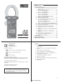
1
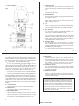
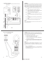
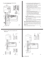
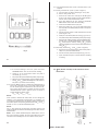
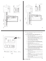
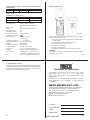
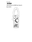
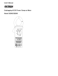
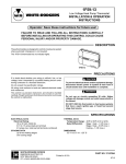
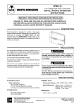
® f 3f f /1f POWER CLAMP MODEL : 4500 USER MANUAL EN 61010-2-032 CAT II 600V Pollution Degree 2 Definition of Symbols : Caution : Refer to Accompanying Documents TABLE OF CONTENTS 1. Features ............................................................................... 2 2. Panel Description ............................................................... 4 3. Operating Instructions ...................................................... 6 3.1. AC+DC 1f2W Power (W) and Power Factor (PF) measurement ........................................................... 6 3.2. AC+DC Voltage Measurement ................................ 8 3.2.1. V + Hz Dual Display ...................................... 8 3.2.2. V + A Dual Display ......................................... 9 3.3. AC+DC Current Measurement ................................ 10 3.3.1. A + Hz Dual Display .................................... 10 3.3.2. V + A Dual Display ....................................... 11 3.4. AC+DC 1f2W Apparent/Reactive Power Measurement (KVA+KVAR) .................................. 11 3.5. Phase Angle Measurement ................................... 12 3.6. 3f AC+DC Balanced Power Measurement .......... 14 3.6.1. W+ PF Dual Display .................................... 14 3.6.2. KVA + KVAR Dual Display .......................... 15 3.6.3. V + A Dual Display ....................................... 15 3.7. 3f3W AC+DC Unbalanced Power Measurement 16 3.8. 3f4W AC+DC Unbalanced Power Measurement 21 3.9. 1f3W Power Measurement .................................. 27 3.10. Calculation of 3f4W Power Factor (PF) ............... 31 3.11. Improving Power Factor of a 3f4W Power System ................................................................... 31 3.12. Improving Power Factor of a 3f Balanced Power System ................................................................... 31 3.13. Improving Power Factor of a 1f2W Power System ................................................................... 32 3.14. Phase Sequence Indication (for PF > 0.1) ........... 33 3.15. Recording Data in Volatile Memory ....................... 35 3.16. Reading Data in Memory ....................................... 35 4. Specifications ................................................................... 36 5. Battery Replacement ....................................................... 39 6. Maintenance & Cleaning ................................................. 40 1. Features 1. 3f4W, 3f3W, 3f Balanced, 1f2W and 1f3W Power Measurement. 2. AC+DC true power, and True RMS AC Voltage and Current 3. AC+DC 2000A. AC 600V, DC 800V 4. AC+DC 1200KW(1f), AC+DC 2000KW (3f) Caution : Risk of Electric Shock Double Insulation Over-voltage Category I (CAT I) : Equipment for connection to circuits in which measures are taken to limit the transient over-voltages to an appropriate low level. Over-voltage Category II (CAT II) : Energy-consuming equipment to be supplied from the fixed installation. 5. Dual Display V+Hz, A+Hz, W+PF, KVA+KVAR, V+A 6. Phase Angle Measurement 7. 3f RST(L1L2L3) Sequence Indication. 8. Memory of 4 records. 9. DCA/DCW Auto Zero when power clamp powering on. 10. AC/DC Auto Detection 11. Auto range. Over-voltage Category III (CAT III) : Equipment in fixed installations. WARNING : If the clamp meter is used in a manner Not specified by the manufacturer, the protection provided by the clamp meter may be impaired. 3 4 4500 : 28-09-2012 1. Panel Description Fig.1 1. Transformer Jaw This is used to pick up current signal. To measure AC+DC current or AC+DC power, conductor must be endosed by the jaw. 2. Transformer Trigger This is used to open the jaw. 3. Data Hold Button Once this button is pressed, reading will be held in the LCD. Press again to release it. 4. Function Selection and On/Off Switch This is used to sealed the function users desired, such as KW, V, A, Phase, KVA or 3f. 5. LCD This is a 4 digits Liquid Crystal Display with maximum indication of 9999. Function symbols, units, sign, decimal points, low battery symbol and zero symbol are included. 6. Units Symbols Once a function is selected, corresponding unit (KW, V, A, Phase, KVA, or 3f) will be displayed in LCD. f4W Select Button (3 wire or 4 wire systems) 7. 3f f 3W and 3f If the 3f system is not a balanced system, users can press this button to select between 3f3W, 3f4W or a balanced system. Once pressed, LCD will show symbol of 3f3W or 3f4W depends on the function selected. 8. Read/Next Button When the rotary switch is set at 3f function, the button is used as a NEXT button In the 3f balanced system mode, pressing the NEXT button will enable users to select W+PF, KVA+KVAR or V+A to be displayed. In the 3f3W system mode, Pressing the NEXT button to 5 6 store the measured values WRS(L1L2) and WST(L2L3) After two values are measured and stored, the microprocessor inside the power Clamp will add the two vaIues together, display the result in LCD and show the symbol of WRST to represent W3f3W.To start another W3f3W measurement, press the NEXT button again. In the 3f4W system mode. Pressing the NEXT button to store the measured values WR(L1) WS(L2) and WT(L3) After three values are measured and stored, the microprocessor inside the clamp will add the three values together, display the result in LCD and show the symbol ot WRST to represent W3f4WTo start another W3f4W measurement, press lhe NEXT button again. If the rotary is not set at the 3f function, the button is used as a READ button. If users ever store data in the memory by:pressing REC button, pressing the READ button will retrieve the data from the memory. First the data number will be shown in LCD, then the data stored. Once READ function is enabled, symbol of REC and NO. will be shown in LCD to indicate the power clamp is in READ mode. The reading shown in LCD is not current reading but data stored in memory. To exit READ function. turn the rotary switch to change funclion. 9. V input Terminal This terminal is used as input for voltage measurements. 10. COM Terminal This terminai is used as common reference input. 12. REC button The clamp meter can store 4 data in memory. Once the button is pressed, the data number will be shown in LCD. A REC symbol will be shown in LCD if any data is stored. If the memory is full, FULL will be show in LCD. To clear memory, users need to turn the power off and on again. 13. Low Battery Symbol When this symbol appears, it means the battery voltage drops below the minimum required voltage. Refer to Section V for battery replacement. 14. REC and NO. symbols If users observe REC is shown that means data is stored in memory. If users observe both REC and NO. are shown, that means readings shown in LCD are data stored in memory not current data measured. Test equipment risk assessment (UK recommendation) Users of this equipment and/or their employers are reminded that health and safety legislation requires them to carry out valid risk assessments of all electrical work so as to identify potential sources of elctrical danger and risk of elctrical injury such as from inadvertent short circuits. Where assessments show that the risk is significant than the use of fused test leads constructed in accordance with the HSE note GS38 "Electrical Test Equipment for use by Electricians" should be used. 11. DC A/W ZERO button When users find the reading of A or W is not zero, press this button once will zero the A or W reading (Users do not need to press and hold the button). When the power clamp is doing the zero action, a symbol of ZERO will be shown in LCD. 7 8 4500 : 28-09-2012 3. Operating instruction 3.1 WARNING : AC + DC 1f2W Power (W) and Power Factor (PF) measurement. Do not clamp on to any conductor when turning on the power of power clamp. Because the power clamp will auto zero the residual magnet remained in the jaws at the moment the power clamp is tumed on. If users clamp on to conductor with current flowing through, the reading measured later will be inaccurate. 3.1.1. Turn the power on without jaws damping on to any wire. 3.1.2. Set the rotary switch at W (refer to figure 2). 3.1.3. If the watt reading is not zero. press the DCA/DCW ZERO button once to zero the watt reading 3.1.4. Insert the test leads into the inpul jack. 3.1.5. Connect the test prod of COM (black) terminal to the neutral line. 3.1.6. Connect the test prod of V (red) terminal to the power line. 3.1.7. Clamp on to the line where V (red) terminal is connected. 3.1.8. The power clamp with automatically select proper range. 3.1.9. Read the Watt and PF values displayed in LCD. NOTE : The “+” sign printed on jaw must face the power source for accurate measurement. Fig.2 9 3.2. AC + DC Voltage Measurement. 3.2.1. V + Hz Dual Display 10 WARNING : Maximum input for DC V is 1000, and for AC V is 750. Do not attempt to take any voltage measurement that exceeds the limits. Exceeding the limits could cause electrical shock and damage to the clamp meter. a. Set the rotary switch at V (refer to figure 3). b. Insert the test leads into the input jack. c. Connect the test prods of the test leads in PARALLEL to the circuit to be measured. d. The power clamp will automatically select proper range. e. Read the voltage and Frequency values displayed on the LCD. NOTE : The sensitivity for voltage frequency measurement is 1V. and the frequency range is 10 - 400Hz. If the frequency is < 10 Hz, LCD will show 0 Hz. If the frequency is > 400 Hz, LCD will show OL. 3.2.2. V + A Dual Display Follow Ihe instruction in section 3.6.3 3f AC+DC Balanced Power Measurement V + A. Then users can monitor V and A at the same time from LCD. Fig.3 11 12 4500 : 28-09-2012 3.3 AC+DC Current Measurement 3.3.1. A + Hz Dual Display Fig.4 13 KVAR=KVA*sin u WARNING : Before taking measurement, users must make sure the current (A) reading is zero by setting the rotary switch at A position. If the current reading is not zero, users might get an incorrect KVA and KVAR values. 3.5 Phase Angle Measurement Fig.5 WARNING : 1. Do not clamp on to any conductor when turning on the power of power clamp. 2. Make sure that all the test leads are disconnected from the power clamp’s terminals for current measurement. a. Set the rotary switch at A (refer to figure 4). b. Push and hold the DCAIDCWZERO once to zero the reading. c. Press the trigger to open the jaw and fully endose the conductor to be measured. No air gap is allowed between the two half jaws. d. The power clamp will automatically select proper range. e. Read the current and frequency values displayed in LCD. NOTE : The sensitivity for current frequency measurement is 5A, and the frequency range is 10 - 400Hz. If the frequency is < 10 Hz, LCD will show 0 Hz. If the frequency is > 400 Hz, LCD will show OL. 3 3.2. V + A Dual Display Follow the instruction in section 3.6.3 3f AC+DC Balanced Power Measurement V + A. Then users can monitor V and A at the same time from LCD. f 2W Apparent/Readive Power Measurement 3.4. AC+DC 1f (KVA+KVAR) Before any measurement, zero the current (A) reading. Then set the rotary switch at KVA. The rest of the procedures are the same as section 3.1 (AC+DC 1f2W Power (W) and Power Factor (PF) measurement). Refer to figure 2 for test leads connection and clamping of jaw. KVAR is a calculated value, and its accuracy greatly depends on the accuracy of V, A and KW. To obtain a more accurate KVAR value when PF is greater than 0.91 (u<250) measure the phase angle and obtain the KVAR from the following equation for 14 a pure sine wave. 3.5.1. Make sure the current reading is zero by setting the rotary switch at A. If the current reading is not zero, press the DCA ZERO button. 3.5.2. Set the rolary swiich at Phase (refer to figure 5). 3.5.3. Insert the test leads into the input jack. 3.5.4. Connect the test prod of the COM (black) terminal to Ihe reference line. 3.5.5. Connect the test prod of the V (red) terminal to the voltage signal to be detected. 3.5.6. Clamp on to the wire where V (red) terminal is connected. 3.5.7. If current signal is detected from the jaws, the phase angle will be displayed in degree in LCO together with the frequency of voltage. 3.5.8. If the current signal is not detected from the jaws, only the frequency of voltage will be displayed while the phase angle is left blank. WARNING : Before taking measurement, users must zero the current (A) reading to avoid incorrect reading of phase angle. To check if current is zero, turn the rotary switch to current (A) function. NOTE : INDUCTIVE LOAD : Negative phase angle means current signal lags behind voltage signal. If connection is correct, negative phase angle also means inductive load. CAPACITIVE LOAD: Positive phase angle means current signal leads ahead voltage signal. If connection is correct, positive phase angle also means capacitive load. NOTE: The “+” sign printed on jaw must face the power source for correct result. 15 16 4500 : 28-09-2012 Fig.6 3.6 3f AC+DC Balanced Power Measurement 3.6.1. W + PF Dual Display a. Turn the power on without clamping on to any wire. b. Set the rotary switch at 3f (refer to figure 6). c. LCD will show 3f3W, 3f4W, and BAL symbols indicate balanced power measurement. d. If the watt reading is not. zero. press the DCA/DCW ZERO button once to zero the watt reading e. Insert the test leads into the input jack. f. Select one phase (eg. R or L1) as COM and Connect the test prod of COM (black) terminal to that phase (eg. R or L1). g. Connect another test prod to the second phase (eg. S or L2). h. Clamp on to the third phase (eg. T or L3). i. The power clamp will automatically select proper range. j. Read the Watt and PF values displayed in LCD. k. To see KVA and KVAR. press the NEXT button. I. To see V and A, press the NEXT button again. m. To return to display of W and PF, press the NEXT button again. 3.6.2. KVA + KVAR Dual Display Follows steps from a to j in section 3.6.1 Then press the NEXT once, and wait for 1.5 seconds. The LCD display will show the values of KVA and KVAR. 3.6.3. V + A Dual Display Follows, steps from a to j in section 3.6.1. Then press the NEXT twice, and wait for 1,5 seconds. The LCD display will show the absolute values of V and A. NOTE : Specific selection of each phase is not required in 3f. balanced power measurement. As long as each prod and the jaws are connected to different phases, the reading is always correct. The “+” sign printed on jaw must face the power source for accurate measurement. NOTE : To find out it load is capacitive or inductive, refer to section 3.5 Phase Angle Measurement for details. 17 18 Fig.7 f3W (No neutral) AC+DC Unblanced Power 3.7. 3f Measurment. Fig.8 19 20 4500 : 28-09-2012 3.7.1. Two measurements of WRS (or WL1L2) and WST(or WL2L3) are required 3.7.2. Firstly, measure WRS (or WL1L2) (refer to figure 7). a. Turn the power on without clamping on to any wire. b. Set the rotary switch at 3f. c. Press the 3f button once. and only the 3f3W symbol is lett in LCD. At this momeni, the WRS symbol blinks to instruct users to take measurement of WRS d. If the watt reading is not zero, press the DCA/DCW ZERO button once to zero the watt reading e. Insert the test leads into the input jack. f. Select one phase (eg. S or L2) as COM and connect the test prod of the COM (black) terminal to that phase (eg. S or L2). g. Connect the test prod of V (red) terminal to the second phase (eg. R or L1). h. Clamp on to the same phase as in step g. (eg. R or L1). i. The power clamp will automalically select proper range. j. Wait until the reading is stable, press the NEXT button, and WRS (WL1L2) symbol will disappear. At this moment, WRS is stored in the memory, and WST (WL2L3) symbol appears and blinks to instruct users to take measurement of WST(WL2L3). 3.7.3. Secondly, measure WST, (or WL2L3) (refer to figure 8). Fig.9 a. Disconnect the test prod from the phase where jaws is clamp on in previous measurement. b. Connect the test prod to the third phase (eg. T or L3). c. Open and close the jaws, so power clamp is clamping to nothing 21 22 d. If the watt reading is not zero, press the DCA/ DCWZERO button once to zero the watt reading f 4W (Neutral included) AC+DC Unblanced Power 3.8. 3f Measurment. e. Clamp on to the third phase where test prod is connected (eg. T or L3) f. The power clamp will automatically select proper range. g. Wait until the reading is stable, press the NEXT button, and WST (or WL2L3) symbol will disappear. At this moment, WST(or WL2L3) is stored in the memory, 3.7.4. Once the NEXT button is pressed after measurements of WRS (or WL1L2) and WST (or WL2L3), the power clamp will add the two values together and show the result on Ihe LCD. WRST symbol will be shown to indicate the watt of 3f3W unbalanced Power (refer to figure 9). PF is not shown in 3f3W unbalanced power mode. W3f3W = WRST = WRS(L1L2) + WST(L2L3) Fig.10 NOTE: Once a phase is selected as COM, users can not change this selection in the subsequent measurement. For example, if S (or L2) phase is selected, S (or L2) phase is always connected to the COM of power clamp during measurement of WRS (or WL1L2) and WST (or WL2L3) in 3f3W unbalanced power. NOTE : The “+” sign printed on jaw must face the power source, and make sure all the connections and clamping are corred for correct measurement. NOTE : In the 3f3W unbalanced power measurement, one of WRS or WST could be negative. So users must make sure all the connections and clamping are correct to obtain correct power. 23 24 4500 : 28-09-2012 Fig.12 Fig.11 25 26 27 3.8.1. Three measurements of WR(or WL1), WS (or WL2) and WT (or WL3) are required. 3.8.2. Firstly, measure WR (or WL1) (refer to figure 10). a. Turn the power on without clamping on to any wire. b. Set the rotary switch at 3f. c. Press the 3F button twice, and only the 3f4W symbol is left in LCD. At this moment, the WR symbol blinks to instruct users to take measurement of WR. d. If the watt reading is not zero, press the DCA/DCW ZERO button once to zero the watt reading. e. Insert the test leads into the input jack. f. Connect the neutral line to the COM (black) terminal. g. Connect the test prod of the V (red) terminal to the first phase (eg. R or L1). h. Clamp on to the same phase (eg. R or L1). i. The power clamp meter will automatically select proper range. j. Wait until the reading is stable; press the NEXT button, and WR symbol will disappear. At this moment, WR is stored in the memory and WS symbol appears and blinks to instruct users to take measurement of WS. 3.8.3. Secondly, measure WS (or WL2) (refer to figure 11) a. Disconned the test prod from the phase where jaws is clamp on in 3.7,2. b. Connect the test prod of the V (red) terminal to the second phase (eg. S or L2). c. Open and Close the jaws, so Clamp meter is clamping to nothing. d. If the watt reading is not zero, press the DCA/DCW ZERO button once to zero the watt reading e. Camp on to phase where test prod is connected (eg. S or L2 phase) f. The power clamp will automatically select proper range. Fig.13 28 4500 : 28-09-2012 g. Wait until the reading is stable, press the NEXT button, and WS symbol will disappear. At this moment, WS is stored in the memory and WT flashes in the display. 3.8.4. Thirdly, measure WT, (or WL3) (refer to figure 12) a. Disconnect the test prob from the phase where jaws is clamp on in 3.7.3. b. Connect the test prod of the V (red) terminal to the third phase (eg. T or L3 phase). c. Open and close the jaws, so power clamp is clamping to nothing. d. If the watt reading is not zero, press the DCA/DCW ZERO button once to zero the watt reading e. Clamp on to the phase where test prob is conneted (eg. T or L3). f. The power clamp will automatically select proper range. g. Wait until the reading is stable, press the NEXT button, and WT symbol will disappear. At this moment, WT is stored in the memory. 3.8.5. Once the NEXT button is pressed after measurements of WRWSand WT the power clamp will add the three values WR, WS and WT together and show the result on the LCD. WRST symbol will be shown to indicate the watt of 3f4W unbalanced power (refer to figure 13). PF is not shown in 3f4W unbalanced power measurement. W3f4W = WRST = WR(L1) + WS(L2) + WT(L3) NOTE : The “+” sign printed on jaw must face the power source, and make sure all the connetions and clamping are correct for correct measurement. Note : In the 3f4W unbalanced power measwement, all three WRor WS and WT must be positive. If users find one negative power, check the connection of test leads and clamping of jaw. Make sure all the connections and clamping are correct to obtain correct power. 3.9 1f f 3W Power Measurment. Fig.14 30 29 Fig.16 31 Fig.15 32 4500 : 28-09-2012 1f3W power measurement is similar to 3f3W unbalanced power measurement except the nomendature is different. 3.9.1. Two measurements of WRS (or WL1G) and WST (or WL2G) are required 3.9.2. Firstly, measure WRS (or WL1G) (refer to figure 14). a. Turn the power on without clamping on to any wire. b. Set the rotary switch at 3f c. Press the 3f button once, and only the 3f3W symbol is left in LCD. At this moment. the WRS symboI blinks to instruct users to take measurement of WRS(L1G). d. If the watt reading is not zero, press the DCA/DCW ZERO button once to zero the watt reading e. Insert the test leads into the input jack. f. Connect the test prod of the COM (black) terminal to ground. g. Connect the test prod of V (red) terminal to the second phase (eg. L1). h. Clamp on to the same phase as in step g. (eg. L1). i. The power clamp will automatically select proper range. j. Wait until the reading is stable, press the NEXT button, and WRS (WL1G) symbol will disappear. At this moment, (WRS(L1G)) is stored in the memory and WST (WL2G) symbol appears and blinks to instruct users to take measurement of WST (WL2G). 3.9.3. Secondly, measure WST (or WL2G) (refer to figure 15). a. Disconnect the test prob from the phase where jaws is clamping on in the previous measurement. b. Connect the test prob to the L2 line. c. Open the jaws, so clamp meter is clamping to nothing. 33 3.11. Improving Power Factor of a 3f4W Power System 3.11.1. Measure KVARR (or KVARL1), KVARS (or KVARL2), KVART (or KVARL3) values of each phase. 3.11.2. Based upon the measured values, users can purchase required 3f or 1f capacitor at rated voltage and frequency to improve power factor. 3.11.3.If value of capacitance is needed, users can obtained the value by the following equation. Capacitance (Farad) = KVAR(L1) = KWR(L1) KWS(L2) KWT(L3) ; KVAS(L2) = ; KVAT(L3) = PFR(L1) PFS(L2) PFT(L3) KVA3f4W = KVAR(L1) + KVAS(L2) + KVAT(L3) PF3f4W = KW3f4W KVA3f4W 34 3.13. Improving Power Factor of a 1f2W Power System 3.13.1. Measure KVAR value of a 1f2W power system. 3.13.2. Based upon the measured value, users can purchase required capacitor at rated voltage and frequency to improve power factor. 3.13.3. If value of capacitance is needed, users can obtained the value by the following equation. Capacitance (Farad) = KVAR *1000 2pfV where f : frequency in Hz V : phase voltage 3.11.4. It is recommended that the KVAR value of the capacitor should be a little less than the value measured. 3.12. Improving Power Factor of a 3f Balanced Power System 3.12.1. Measure KVAR3f value of a balanced system. 3.12.2. Based upon the measured value, users can purchase required 3f capacitor at rated voltage and frequency to improve power factor. 3.12.3.If value of capacitance is needed, users can obtained the value by the following equation. Capacitance (Farad) = d. If the watt reading is not zero, press the DCA/DCW ZERO button once to zero the watt reading e. Clamp on to the L2 line where test prob is connected to. f. The power clamp will automatically select proper range. g. Wait until the reading is stabIe, press the NEXT button. and WST (or WL2G) symbol will disappear. At this moment, WST(or WL2G ) is stored in the memory, 3.9.4. Once the NEXT button is pressed after measurements of WRS(or WL1G) and WST (or WL2G) the power clamp will add the two values together and show the result on the LCD. W1f3W = W RST = W RS(L1G) + W ST(L2G) W RST symbol will be shown to indicate the watt of 1f3W unbalanced Power (refer to figure 16). PF is not shown in 1f3W unbalanced power mode. 3.10. Calculation of 3f4W Power Factor (PF) 3.10.1.As measuring 3f4W unbalanced power, use the REC button to record the individual power factor (KWR(L1), PFR(L1), KWS(L2), PFS(L2), KWT(L3) and PFT(L3)) of each phase in mernory. 3.10.2. With those data, 3f4W power factor can be calculated by the fallowing equation. 2 3.13.4. KVAR *1000 2pfV 2 where f : frequency in Hz V : phase voltage It is recommended that the KVAR value of the capacitor should be a little less than the value measured. KVAR *1000 2pfV 2 where f : frequency in Hz V : phase voltage 3.12.4. It is recommended that the KVAR value of the capacitor should be a little less than the value measured. 36 35 4500 : 28-09-2012 3.14. Phase Sequence Indication (for PF > 0.1) Fig.17 NOTE : The indication of phase sequence is not limited to 3f balanced power. It can be used in general as long as the PF displayed is greater than 0.1. Set the power clamp In 3f balanced power mode, the power clamp will automatically detect phase. 3.14.1. Set the rotary at 3f. 3.14.2. Connect the voltage input (red terminal) to R (or L1) phase, connect the COM input (black terminal) to S (or L2) phase, and clamp on the T (or L3) phase. When clamp on the T (or L3) phase, the power clamp must face the power source. 3.14.3. If the phase sequence is clockwise, R, S, T sequence will be shown and flashed. (refer to figure 17 ) 3.14.4. If the phase sequence is counterdockwise, T, S, R sequence will be shown and flashed. (refer to figure 17) 3.14.5. If the current signal (where jaws clamp on) is not detected, only one of the R, S or T will be left in LCD. NOTE : The “+” sign printed on jaw must face the power source for correct measurement. 3.15. Recording Data in Volatile Memory The power clamp can store 4 data in its own memory. To store any data displayed in LCD, press the REC button. If the power clamp has stored 4 data already, LCD will display FULL. The data is lost if power is turned off. The REC symbol will be displayed in LCD if any data is stored. NOTE : If users observe REC (only) is shown in LCD, that means some data is stored in memory. 37 3.16. Reading Data in Memory To retrieve data in memory, press the READ button as long as rotary switch is not set at 3ffunction. Once the read button is pressed, the record number will be first displayed. then data is displayed after. Once in the READ function, the REC. NO. symbols will be displayed in LCD. To exit the READ function, turn the rotary switch to change function. NOTE: If users observe both REC and NO. symbols are shown in LCD, users should know that the readings shown in LCD are not current data measured. They are data stored in the memory. 4. Specifications (230C ± 50C) AC ± DC True Power ( PF 0.2 - 1.0, 3f3W, 3f4W, 1f2W and 1f3W) : Range Resolution Accuracy (of rdg) Range 00.01KW ±2.0%±0.05KW AC 600V, DC 800V, 99.99KW ACA/DCA 2000A 100 0.1KW ±2.0%±0.5KW AC 600V, DC 800V, 999.9KW ACA/DCA 2000A 1000 1KW ±2.0%±5KW AC 600V DC 800V, 1200KW ACA/DCA 2000A KW Autoranging Map (PF 0.2 - 1.0, 3f3W, 3f4W, 1f2W and 1f3W) 0V - 200V 200V - 600VAC, 200V - 800VDC 0A - 200A 0.00 - 40.00KW 0.00 - 99.99KW 100.0 - 160.0KW 200A - 2000A 0.0 - 400.0KW 0.0 - 999.9KW 1000 - 1600KW 38 AC+DC True Power ( Power Factor 0.2 Power) : Range Resolution Accuracy (of rdg) 00.01KW ±2.0%±0.5KW 99.99KW 100 0.1KW ±2.0%±0.5KW 999.9KW 1000 1KW ±2.0%±5KW 2000KW Power Factor (PF) KW PF = KVA - 1.0, 3f Balanced Range AC 600V, DC 800V. ACA/DCA 2000A AC 600V, DC 800V, ACA/DCA 2000A AC 600V, DC 800V, ACA/DCA 2000A AC+DC Voltage ( True RMS, Crest Factor < 4, Autorange, Overload Protection 800VAC for all range) Accuracy (of reading) Input Range Res. DC, 50/60Hz 40-400Hz Impedance 0-200V 0.1V ±1.5%±5dgts ±2.0%±5dgts 10MV 200-500V 0.1V ±1.5%±5dgts ±2.0%±5dgts 10MV 500-600V 1V ±1.5%±5dgts ±2.0%±5dgts 10MV AC+DC Current (True RMS, Crest Factor < 4) : Accuracy (of reading) Overload Range Res. DC, 50/60Hz 40-400Hz Protection 0 - 200A 0.1A ±1.5%±5dgts ±2.0%±5dgts AC 3000A 200 - 500A 0.1A ±2.0%±5dgts ±2.5%±5dgts AC 3000A 500-2000A 1A ±2.5%±5dgts ±3.0%±5dgts AC 3000A AC+DC KVA (Apparent Power) V*A (KVA) = 1000 AC+DC KVAR (Reactive Power) (KVAR) = (KVA)2 - (KW)2 40 39 4500 : 28-09-2012 Phase Angle (50 / 60Hz, must zero current reading before measurement) Range Accuracy Sensitivity Remark -900 to +900 ±2.00 V>100V, A>10A Zero Crossing Detection If a current signal is not detected, the phase angle will be left blank in LCD. Frequency ( if < 10 Hz, Hz = 0) Range Accuracy Sensitivity 50/60 Hz ±2dgts V: >1V, A: >5A 10 - 400 Hz 0.5% ± 2 dgts V: >1V, A: >5A 5. Battery Replacement Indoor Use Conductor Size : Cable F 55mm. (approx.) Bus Bar 65mm(D) x 24mm(W) Battery Type : 9V Display : 2 X 4 Digits Dual Display LCD Range Selection : Auto Overload Indication : OL Power Consumption : 25 mA (approx.) Low Battery Indication : Sampling Time : 0.5 sec. (V and A) 1.6 sec. (W) Operating Temperature : 40C to 500C Operating Humidity : less than 85% relative Altitude : up to 2000M Storage Temperature : -200C to 600C Storage Humidity : less than 75% relative Dimension : 271 x 112 x 46mm (approx.) Weight : 647gms included battery (approx.) Accessories : Carrying bag x 1, Users manual x 1 9V battery x 1 (Installed), Test lead pair x 1, Crocodile test lead pair x 1 41 Fig.18 When the low battery symbol is displayed on the LCD, replace the old battery with new battery. 5.1.Turn the power off and remove the test leads from the power clamp. 5.2.Remove the screws of the bottom case. 5.3.Lift and remove the bottom case. 5.4.Remove the old battery. 5.5.lnsert new 9V battery. 5.6.Replace the bottom case and secure the screws. WARNING : do not touch or adjust any parts inside the power clamp when the bottom case is open. 42 6. Maintenance & Cleaning Servicing not covered in this manual should only be performed by qualified personnel. Repairs should only be performed by qualified personnel. Periodically wipe the case with a damp cloth and detergent; do not use abrasive or solvents. ® Certificate of Calibration We hereby certify that this product has been calibrated and found to be in accordance with the applicable SPECIFICATIONS and STANDARDS. Accuracies of the standard equipment used in this calibration are traceable to the National Standards. MECO METERS PVT. LTD. Plot No. EL-60, MIDC Electronic Zone, TTC Industrial Area, Mahape, Navi Mumbai - 400710 (INDIA) Tel : 0091-22-27673311-16, 27673300 (Board) Fax : 0091-22-27673310, 27673330 E-mail : [email protected] Web : www.mecoinst.com SR. NO. : CHECKED BY : DATE : MODEL NO. : 44 43 4500 : 28-09-2012