1
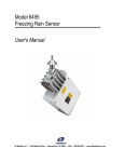
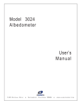
Model 8190
Motor Aspirated Radiation Shield
User's Manual
All Weather Inc. • 1165 National Drive • Sacramento, CA 95834 • USA • www.allweatherinc.com
User's Manual
8190 Motor Aspirated Radiation Shield
CONTENTS
INTRODUCTION ...............................................................................................1
INSTALLATION & CHECKOUT........................................................................1
MARS Installation .........................................................................................1
Probe removal and Installation .....................................................................1
Determining the Type of Probe Mount ....................................................1
Removal—Probe with Fixed Mount .........................................................2
Installation—Probe with Fixed Mount ......................................................2
Removal—Probe with Removable Mounting Blocks ...............................3
Installation—Probe with Removable Mounting Blocks ............................3
THEORY OF OPERATION................................................................................4
CALIBRATION ..................................................................................................4
MAINTENANCE ................................................................................................4
Periodic Maintenance ...................................................................................5
Monthly Maintenance ..............................................................................5
Quarterly Maintenance ............................................................................5
Annual Maintenance ...............................................................................5
SPECIFICATIONS.............................................................................................5
WARRANTY ......................................................................................................5
AWOS WARRANTY..........................................................................................6
Page i
User's Manual
8190 Motor Aspirated Radiation Shield
INTRODUCTION
The Model 8190 Motor Aspirated Radiation Shield (MARS) provides protected mounting for
temperature and humidity probes, shielding them from direct solar heating and precipitation
contact. The Model 8190 is a virtually maintenance-free radiation shield constructed of
heavy-duty, non-corrosive polymer, and featuring a reliable, long-life 12VDC fan for
continuous aspiration. It accommodates one probe: a temperature probe, a humidity probe, or
a combination temperature/humidity probe. All cable terminations to the MARS are made
through weatherproof connectors mounted on the enclosure.
INSTALLATION & CHECKOUT
The MARS is designed for tower installations. Mounting hardware is provided, including
mounting brackets and U-bolts. Consult All Weather Inc. for other mounting options.
MARS INSTALLATION
The MARS should be installed with the vent tube on the right side, pointing down,
approximately five feet above the ground. When installing on the Model 8518-A Foldover
Tower, mount to the hinged side of the tower. Ensure that the sensor cable will reach the
Data Collection Platform connector. To install the MARS, follow the steps below:
1
Lift the MARS into position and attach the horizontal tube to the tower legs using the
supplied mounting brackets and U-bolts.
2 Adjust the positions of the U-bolts to give a level installation. The vertical vent tube
should be vertically level to prevent direct solar radiation from entering the tube.
3 Fasten the U-bolts securely, being careful not to overtighten the horizontal tube's U-bolt,
which could cause deformation of the tube.
PROBE REMOVAL AND INSTALLATION
Two different probe mounting arrangements are found on the 8190. The first uses mounting
blocks that are attached to the probe and so are removed along with the probe. The second
method allows the probe to be removed while leaving the mounting bracket in place. The
following sections explain how to remove and install probes into the MARS in either
situation.
Determining the Type of Probe Mount
When the temperature/RH probe is installed in a fixed mount, it is removed by simply
loosening the mounting screws. When the probe is installed in a removable block mount, the
entire mounting block assembly must be removed along with the probe. To determine if the
mount is fixed or removable, follow the steps below:
1
2
Disconnect power from the MARS. This is important to prevent electrical shock and to
avoid damage to internal wiring, as well as to the fan blades. For AWOS installations,
refer to the Model 1190 DCP User's Manual for instructions in connecting the MARS
and the Model 5190-D Temperature/RH sensor.
The two probe mounting screws are located on the back of the MARS vent tube. Loosen
the two mounting screws 3-4 turns each. Be sure not to remove the screws completely. If
a fixed mount is used, the probe will come free when gently pulled from below. If the
probe is mounted in removable mounting blocks, it will feel loose moving from side-toside but will not move vertically.
Page 1
8190 Motor Aspirated Radiation Shield
User's Manual
Removal—Probe with Fixed Mount
When the temperature/RH probe is installed in a fixed mount, the probe can be removed
simply by loosening the mounting screws.
1
Disconnect power from the MARS. This is important to prevent electrical shock and to
avoid damage to internal wiring, as well as to the fan blades. For AWOS installations,
refer to the Model 1190 DCP User's Manual for instructions in connecting the MARS
and the Model 5190-D Temperature/RH sensor.
2 Tie a piece of string to the probe cable where it emerges from the strain relief.
3 Loosen the two mounting screws 3-4 turns each. Be sure not to remove the screws
completely.
4 Loosen the strain relief, and, holding onto the string, grasp the probe near the bottom,
above where the cable joins the case. Do not remove the probe by pulling the cable.
5 Remove the probe by pulling it gently down and out of the MARS.
6 Disconnect the cable from the probe.
Installation—Probe with Fixed Mount
1 Disconnect power from the MARS. This is important to prevent electrical shock and to
avoid damage to internal wiring, as well as to the fan blades. For AWOS installations,
refer to the Model 1190 DCP User's Manual for instructions in connecting the MARS
and the Model 5190-D Temperature/RH sensor.
2 Connect the probe cable to the probe.
3 To simplify routing of the probe cable and installation of the probe in the vent tube, feed
a piece of string weighted at the end (with a nut, for example) through the horizontal
tube and down through the vent tube.
4 Tie the string to the probe cable and pull the string from the opposite end to guide the
cable up through the vent tube and into the horizontal tube.
5 Form a loose loop of cable at the base of the probe, and secure it with a cable tie so that
the cable forms a U.
6 With the filter end of the probe pointing up, grasp the loop of cable at the base of the
probe and raise the probe up into the vent tube.
7 When you feel the probe make contact with the mount, move it side-to-side as necessary
until it slides into the mount opening.
8 Slide the probe into the mount until the bottom of the probe is 2-3 inches above the
mouth of the MARS vent tube.
9 While holding the probe in place, tighten the mounting screws just enough to secure the
probe, but do not overtighten.. Over-tightening the screws will damage the probe.
10 Pull the remaining slack out of the cable, keeping the cable as straight as possible.
11 Tighten the strain relief until the cable is securely sealed.
12 Route the cable down the tower in the most convenient manner. Lace or strap the cable
approximately every 12 inches. Loose cables will rub against the tower in high winds,
and the cable insulation could be destroyed. Use ultraviolet resistant cable ties, tape, or
metal strapping. Use caution to avoid damaging the outer jacket of the cable.
13 Connect the sensor cable to the data collection unit. For AWOS installations, connect
the sensor wires to the Data Collection Platform (DCP) as explained in the Model 1190
DCP User's Manual.
14 Reapply power to the MARS and check to see that the fan is rotating. Check to ensure
that all mounting hardware is securely fastened. Verify sensor operation.
Page 2
User's Manual
8190 Motor Aspirated Radiation Shield
Removal—Probe with Removable Mounting Blocks
When the temperature/RH probe is installed in removable mounting blocks, the blocks must
be removed along with the probe.
1
Disconnect power from the MARS. This is important to prevent electrical shock and to
avoid damage to internal wiring, as well as to the fan blades. For AWOS installations,
refer to the Model 1190 DCP User's Manual for instructions in connecting the MARS
and the Model 5190-D Temperature/RH sensor.
2 Tie a piece of string to the probe cable where it emerges from the strain relief.
3 Remove the two mounting screws holding the probe mounting blocks in place inside the
vent tube.
4 Loosen the strain relief, and, holding onto the string, lower the probe and mounting
blocks out of the vent tube.
5 Disconnect the cable from the probe.
6 Remove the mounting blocks from the probe by loosening the two set screws.
Installation—Probe with Removable Mounting Blocks
1
4
5
6
7
Disconnect power from the MARS. This is
important to prevent electrical shock and to
avoid damage to internal wiring, as well as to the
fan blades. For AWOS installations, refer to the
Model 1190 DCP User's Manual for instructions
in connecting the MARS and the Model 5190-D
Temperature/RH sensor.
2 Connect the probe cable to the probe.
3 (Refer to Figure 1.) Two mounting blocks are
used to position the probe inside the vent tube.
Slide the first mounting block over the probe and
position it near the filter end of the probe. With
the Model 5190-D probe, position the block so
that the set screw is over the flattened notch in
the probe case. Tighten the set screw just enough
to secure the probe, but do not overtighten.
Figure 1
I t lli th P b M ti Bl k
Over-tightening the screws will damage the
probe. The mounting blocks serve only to position the probe in the center of the vent
tube, not to support it inside the tube. Even with the set screws loose, there is no danger
of the probe dropping out of the MARS.
Slide the second mounting block over the probe and up until it is flush against the first.
Before tightening the set screw, make sure that the mounting screw hole on the opposite
side of the block is aligned with the mounting hole in the first block. Tighten the set
screws, again being careful not to overtighten.
To simplify routing of the probe cable and installation of the probe in the vent tube, feed
a piece of string weighted at the end (with a nut, for example) through the horizontal
tube and down through the vent tube.
Tie the string to the probe cable and pull the string from the opposite end to guide the
cable up through the vent tube and into the horizontal tube.
Form a loose loop of cable at the base of the probe, and secure it with a cable tie so that
the cable forms a U.
Page 3
8190 Motor Aspirated Radiation Shield
8
9
10
11
12
13
14
User's Manual
With the filter end of the probe pointing up, grasp the loop of cable at the base of the
probe and raise the probe up into the vent tube. Align the screw holes in the mounting
blocks with the screw holes in the vent tube.
Replace the two mounting screws to secure the probe mounting blocks inside the vent
tube.
Pull the remaining slack out of the cable, keeping the cable as straight as possible.
Tighten the strain relief until the cable is securely sealed.
Route the cable down the tower in the most convenient manner. Lace or strap the cable
approximately every 12 inches. Loose cables will rub against the tower in high winds,
and the cable insulation could be destroyed. Use ultraviolet resistant cable ties, tape, or
metal strapping. Use caution to avoid damaging the outer jacket of the cable.
Connect the sensor cable to the data collection unit. For AWOS installations, connect
the sensor wires to the Data Collection Platform (DCP) as explained in the Model 1190
DCP User's Manual.
Reapply power to the MARS and check to see that the fan is rotating. Check to ensure
that all mounting hardware is securely fastened. Verify sensor operation.
Theory of Operation
The MARS is designed to adequately ventilate a probe, while at the same time shielding it
from direct and reflected solar radiation and from direct moisture contact. It is constructed of
heavy-duty polymer to limit thermal mass, and thereby preventing radiant heating of
temperature probes by the tubing. Highly reflective white paint is applied to all exterior
surfaces to reflect as much solar radiation as possible.
Air flow through the MARS is virtually free of any obstruction. Spacing is selected to
give maximum air flow and at the same time prevent direct solar contact with the probe.
Fresh air is forced through the MARS by a fan to allow measurement of actual air
temperature. The exhaust vent of the MARS is 44 inches from, and slightly higher than, the
vent tube intake. Any heat developed by the fan motor or the shield itself will be exhausted
away from the vent tube, preventing this heat from re-entering the MARS and being
measured by the temperature probe.
CALIBRATION
No calibration of the Model 8190 is required. To ensure constant air flow rates, periodic
measurements of air flow can be made using hot wire anemometers.
MAINTENANCE
Maintenance of the MARS is generally limited to periodic cleaning and occasional repainting
of exterior surfaces. Instruments housed inside the MARS should be maintained according to
instructions given in the manual for the particular instrument.
Check the MARS for insect activity (cobwebs, hornet's nests, etc.), as well as birds' nests,
and clean out any debris.
The exterior surfaces of the MARS should be free of dirt at all times to prevent internal
heating of the probe. Clean the surfaces regularly with warm water and soap. Repaint the
exterior surfaces as required. During regular maintenance, check the fan housing for signs of
corrosion, and clean and repair, or replace as necessary. The inside of the enclosure may also
need to be cleaned of excessive dirt drawn in by the fan.
Page 4
User's Manual
8190 Motor Aspirated Radiation Shield
Check all cables for signs of wear or damage, especially in areas with high velocity
winds. Check all mounting hardware for corrosion or looseness, and repair or replace as
required.
A noisy fan may be a sign of worn bearings. Replace the fan when noise is evident.
PERIODIC MAINTENANCE
Monthly Maintenance
• Check all cables for signs of wear or damage, especially in areas with high velocity
winds.
• Check the fan for noise that could be a sign of worn bearings. Replace the fan if noise is
evident, or if the fan has failed.
• Check the MARS for insect activity (cobwebs, hornet's nests, etc.), as well as birds' nests,
and clean out any debris.
Quarterly Maintenance
• Check all cables for signs of wear or damage, especially in areas with high velocity
winds.
• Check the fan for noise that could be a sign of worn bearings. Replace the fan if noise is
evident, or if the fan has failed.
• Check all mounting hardware for corrosion or looseness, and repair or replace as
required.
Annual Maintenance
• Clean the exterior surfaces of the MARS with warm water and soap.
• Repaint the exterior surfaces as required.
• Check all cables for signs of wear or damage, especially in areas with high velocity
winds.
• Check the fan for noise that could be a sign of worn bearings. Replace the fan if noise is
evident, or if the fan has failed.
• Check all mounting hardware for corrosion or looseness, and repair or replace as
required.
SPECIFICATIONS
Operating temperature range
Radiation error
Air flow
Fan life
Power
Size
Weight
-40 to +55°C
0.5°F @12VDC and
1000 W/m2 solar radiation
360 ft./min. @12VDC
70,000 hours @ 40°C
8-15VDC, 180mA @12V
42" L x 13.5" H
(107 cm x 35 cm)
10 lbs (4.6 kg)
Warranty
Unless specified otherwise, All Weather Inc. (the Company) warrants its products to be free
from defects in material and workmanship under normal use and service for one year from
date of shipment, subject to the following conditions:
(a) The obligation of the Company under this warranty is limited to repairing or
replacing items or parts which have been returned to the Company and which upon
Page 5
8190 Motor Aspirated Radiation Shield
User's Manual
examination are disclosed, to the Company’s satisfaction, to have been defective in
material or workmanship at time of manufacture.
(b) The claimant shall pay the cost of shipping any part or instrument to the Company. If
the Company determines the part to be defective in material or workmanship, the
Company shall prepay the cost of shipping the repaired instrument to the claimant.
Under no circumstances will the Company reimburse claimant for cost incurred in
removing and/or reinstalling replacement parts.
(c) This warranty shall not apply to any Company products which have been subjected
to misuse, negligence or accident.
(d) This warranty and the Company’s obligation thereunder is in lieu of all other
warranties, express or implied, including warranties of merchantability and fitness
for a particular purpose, consequential damages and all other obligations or
liabilities.
No other person or organization is authorized to give any other warranty or to assume
any additional obligation on the Company’s behalf, unless made in writing and signed by an
authorized officer of the Company.
AWOS WARRANTY
This equipment has been manufactured and will perform in accordance with requirements of
FAA Advisory Circular 150/5220-16C. Any defect in design, materials, or workmanship
which may occur during proper and normal use during a period of 1 year from date of
installation or a maximum of 2 years from shipment will be corrected by repair or
replacement by All Weather Inc.
Page 6
All Weather Inc.
1165 National Drive
Sacramento, CA 95818
Fax: 916.928.1165
Phone: 916.928.1000
Toll Free: 800.824.5873
8190-001
Rev. H
ECO 0733
April, 2006