1
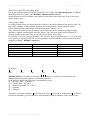
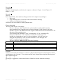
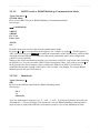
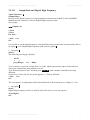
HD2003-HD2003.1 Three-Axis Ultrasonic Anemometer User’s Manual Rev.2.0 February 2006 © 2006 Delta Ohm Srl, All Rights Reserved HD2003 – HD2003.1 Ultrasonic Anemometers Rev.2.0 February 2006 INDEX 1. Introduction 1.1. Conventions 1.2. Models 1.2.1. Heaters Option 1.3. Features 1.4. Operating Modes 1.5. Specifications 1.6. (HD2003 Model) Temperature – Relative Humidity - Pressure Sensors 2. Installation and Maintenance 2.1 Packaging 2.2 Mounting and Positioning 2.3 Alignment 2.4 Electrical Connections 2.4.1 Power Supply and Earthing 2.4.2 RS232 Serial Communication Mode 2.4.3 RS485 Multidrop Communication Mode 2.4.4 Analog Output Mode 2.5 Maintenance 3. Programming 3.1. Introduction 3.2. RS232 Serial Communication Mode 3.2.1. Parameter Setup 3.2.2. Measuring mode 3.2.2.1. RS232 Serial Mode Examples 3.2.3. Setup 3.2.3.1. Baud rate 3.2.3.2. Gain 3.2.3.3. Minimum Threshold 3.2.3.4. Average Interval 3.2.3.5. Analog Output Format 3.2.3.6. Output Quantities 3.2.3.7. Unit of Measurement 3.2.3.8. Sonic Transducer Heating 3.2.3.9. RS232 Serial or RS485 Multidrop Communication Mode 3.2.3.10. Identicode 3.2.3.11. Output Rate and Digital High Frequency 3.2.4. Logging 3.3. RS485 Multidrop Communication Mode 3.3.1. Parameter Setup 3.3.2. HD2003 Communication Protocol 3.3.2.1. S Command (Setup) 3.3.2.2. M Command (Output Data) 3.3.2.3. H Command (Digital High Frequency enable ) and L Command (Digital High Frequency disable ) 3.4. Analog Output Mode 3.4.1. Analog Output Mode Examples 4. How to Order 4.1 Order codes Delta Ohm – Caselle di Selvazzano (PD) ITALY 1 HD2003 – HD2003.1 Ultrasonic Anemometers Rev.2.0 February 2006 1. Introduction Ultrasonic Anemometers allow to detect surface wind speed and direction. These instruments measure the transit time of the ultrasonic pulse between a pair of opposite sonic transducers, in both directions. From the measurement of tA and tR times, you can trace to the wind speed component in the direction of the two transducers, through the formula: V = D/2 · (1/tA – 1/tR) Where: D = distance between two transducers. tA = forward transit time tR = backward transit time This formula ensures that the wind speed does not depend on Pressure, Temperature and Humidity. Three couples of transducers allow to make a three-axis vector measurement of wind. 1.1 Conventions ♦ Definitions of the anemometric quantities measured by the HD2003. The wind direction is established through the calculation of angles: azimuth. The azimuth is the angle that defines the position of the wind flow along the Horizontal Plane, with reference to the direction from which the wind itself is coming. The angle is calculated from 0° to 360° clockwise along the Horizontal Plane. The origin 0° is the direction of Geographical North. The HD2003 built-in integrated compass measures the magnetic azimuth , with reference to Magnetic North. elevation. This is the angle that defines the position of the wind flow along the Vertical Plane. It varies from +/-60° along the Vertical Plane: positive inclinations are those over the Horizontal Plane while the negative ones are those under it. The wind speed is calculated in terms of intensity of components or resultants: SoW, SUV and SoS. The intensity of wind speed is indicated by SoW, that of its component along the Horizontal Plane U-V is indicated by SUV, while that of sound by SoS. U-V-W. These are the three Cartesian components of wind speed. If we draw a Cartesian plane with U and V along the Horizontal Plane, W will be the Vertical Axis. The “V” direction coincides with Geographical North and, consequently, the “U” will coincide with East and the “W” with the vertical. ♦ Other conventions F.S. and Zero. F.S. identifies the Full Scale of a quantity, while Zero identifies the Scale Minimum Value. Factory Default. The Factory Default corresponds to the value of a factory set parameter, when first programming an instrument which comes out of the production department. Internal Refresh. It represents the automatic frequency by which all the calculations are refreshed according to the set average intervals. Delta Ohm – Caselle di Selvazzano (PD) ITALY 2 HD2003 – HD2003.1 Ultrasonic Anemometers Rev.2.0 February 2006 Symbols. The keys of an IBM compatible PC keyboard are identified with a white text on a black background, for example: [Esc] = Esc key, [Enter] = Enter key, [A] = A key One ASCII generic character, or several ASCII generic characters can be identified with the symbol: <name> , where name is any expression that gives the title to that character. Example of peculiar characters: <CR> = Carriage Return <LF> = Line Feed Output Data. It is the digital string of all formatted measuring data available for RS232 and RS485 Serial communication interfaces. 1.2 Models The code HD2003 mentioned in this manual refers to both models: HD2003 HD2003.1 They represent the same kind of Anemometer, except for the fact that the HD2003 has the following built-in sensors: Temperature, Relative Humidity and Pressure, in order to measure these additional output quantities. When necessary, the difference between the two models is unequivocally underlined. 1.2.1 Heaters Option The HD2003 is guaranteed to function in temperatures as low as –20°C if ice or snow is absent, without any heating circuits for sonic transducers. Temperature conditions below –20°C, or temperatures around 0°C when snowing or ice possibly forms on the transducers, prevent the HD2003 from functioning correctly, making the use of the heaters option essential. The heating circuit intervenes at temperatures below +5°C, with a minimum additional power of 4W (with temperature no lower than –10°C), preventing the formation of ice, and ensuring that the HD2003 functions correctly even during sleet or snow. The models equipped with the heaters option are named with the additional letter R: HD2003R HD2003.1R 1.3 Features The HD2003 main features are: ♦ Determination of anemometric quantities with different units of measurement: wind speed and direction, U-V-W Cartesian components, sonic temperature and speed. ♦ (HD2003 Model) Additional quantities measured: Temperature, Relative Humidity, Pressure. ♦ 5 analog outputs in current or voltage, with different ranges. ♦ Digital communication interfaces: RS232 Serial and RS485 Multidrop. ♦ Digital strings of output data at a configurable emission frequency. ♦ Average intervals for all output quantities, configurable at 1÷60 sec or at 1÷60 min. ♦ Processing and validity Algorithms for raw measurement signals to provide the measurement of the anemometric quantity with ±1% precision. ♦ Acquisition mode in Digital High Frequency with data output at 50 Hz. Delta Ohm – Caselle di Selvazzano (PD) ITALY 3 HD2003 – HD2003.1 Ultrasonic Anemometers Rev.2.0 February 2006 ♦ Self-diagnosis with checking and error reporting. ♦ Reliability and precision for the whole measurement field, without any need for further calibrations. ♦ Flexible and easy-to-use operating software which can be adapted to the customer’s requirements through a computer interface. ♦ Setup user interface and software upgrade via RS232 or RS485. ♦ Compass with magnetoresistive sensor for automatic alignment to the Magnetic North. ♦ No moving parts, with reduced maintenance and servicing costs. ♦ Robust construction, apt to operate continuously in severe climatic conditions. ♦ Low power consumption. ♦ (On request) Heaters Option: Sonic transducers integrated heating device, to prevent ice and snow formation, ensuring a correct functioning even when sleeting or snowing. 1.4 Operating Modes The HD2003 has four operating modes: ♦ RS232 Serial Communication Mode (Chap. 3.2) A connection over a RS232 Serial line is established between a Host Computer and one HD2003 Anemometer. The Host Computer (Slave) is continuously receiving on its RS232 serial port, Output Data digital strings, which are automatically supplied by HD2003 (Master), with its own frequency (configurable at a cadence from 1 to 3600s). In this mode the Setup user interface can be managed from the computer. ♦ RS485 Multidrop Communication Mode (Chap. 3.3) A RS485 Multidrop network can be established between a Host Computer and several HD2003 Anemometers (up to 32). The Host Computer (Master) sends a command to the univocal address of a HD2003 (Slave). Only the Anemometer which is identified by that address answers on request, giving the Output Data. In this mode the command to activate the Setup user interface is available. ♦ Digital High Frequency Mode (Chap. 3.2.3.11 and Chap. 3.3.2.3) When on RS232 Serial communication mode, the Digital High Frequency functioning can be set up, obtaining the digital output in RS232 of quantities at a fixed frequency of 50 Hz, with a baud rate=115200 and for 4 measurement quantities at most. When on RS485 Multidrop communication mode, a command for activating the Digital High frequency can be sent. Then, any command for requiring a measurement can be sent to the HD2003 up to a maximum frequency of 50 Hz, with a baud rate=115200 and for 4 measurement quantities at most. ♦ Analog Output Mode (Chap. 3.4) All measurement quantities can be configured to be converted into 5 analog outputs in current or voltage, available in different measurement ranges. This mode is always active, combined with the RS232 Serial and RS485 Multidrop modes. When on Digital High Frequency mode, the 5 analog outputs are still available with a refresh of 1Hz. The RS232 Serial and RS485 Multidrop Communication modes are alternative: only one of them can be active. Their activation is obtained via software (see Chap. 3.2.3.9) , subsequently switching the HD2003 off and on. It is always possible to return to RS232 Serial mode by providing a suitable command when switching the HD2003 on. Delta Ohm – Caselle di Selvazzano (PD) ITALY 4 HD2003 – HD2003.1 Ultrasonic Anemometers 1.5 Rev.2.0 February 2006 Specifications Output quantities ¾ ¾ ¾ ¾ ¾ ¾ ¾ Anemometric Meteorological Heading Wind Speed Unit of measurement Range Resolution Accuracy Wind Direction Range Resolution Accuracy Sound Speed Range Resolution Accuracy Sonic Temperature Range Resolution Accuracy Compass Range Resolution Accuracy wind direction and speed, U-V-W components, sound speed, sonic temperature (HD2003 Model) Pressure, Temperature, Relative Humidity Compass with magnetic azimuth 0÷360° 0.1° ± 1° Moving Averages Ultrasonic rate 1÷60 sec / 1÷60 min 60Hz m/s, cm/s, km/h, knots, mph 0 ÷ 60 m/s (216 km/h) 0.01 m/s ± 1% of reading Azimuth: 0 ÷ 360° Elevation: ± 60° 0.1 ° ±1° 300 ÷ 380 m/s 0.01 m/s ± 1% of reading -40 +60°C 0.1 °C ± 1 °C Digital Outputs ¾ Quantities ¾ ¾ ¾ Communications Baud rate Output Rate Anemometric output quantities and compass (HD2003 Model) Pressure, Temperature, Relative Humidity RS232 full duplex, RS485 Multidrop half duplex 9600 ÷ 115200 bit/sec Normal mode (Slow): 1 ÷ 3600 sec Digital High Frequency (Fast) : fixed 1/50s Analog Outputs ¾ ¾ ¾ Quantities Range Resolution 5 to be selected from all the output quantities available (anemometric, compass, meteo) 0-20 mA, 4-20 mA, 0÷1V, 0÷5V, 0÷10V, 1÷5V 14 bits max Power Supply ¾ ¾ Range Power 12 ÷ 30 Vdc < 2W (Typically: 110mA @ 15Vdc) < 6W Models with heaters and environment temperature not lower than –10 °C Heaters Option (On request when placing the order). Heating with automatic temperature control on sonic transducers, to prevent ice and snow formation and ensure a correct functioning even when sleeting or snowing. Weight. ♦ HD2003 ♦ HD2003.1 : 2.1 Kg. : 1.5 Kg. Environmental Conditions. ♦ Temperature Range ♦ EMC ♦ Precipitation ♦ Humidity -40 +60 °C CE Regulations Operation ensured up to 300mm/hr 0% ÷ 100% RH The HD2003 application fields are continuously developing, thus Delta Ohm reserves the right to change the above-mentioned specifications without prior notice. Delta Ohm – Caselle di Selvazzano (PD) ITALY 5 HD2003 – HD2003.1 Ultrasonic Anemometers 1.6 Rev.2.0 February 2006 Temperature – Relative Humidity – Pressure Sensors (HD2003 Model) Temperature. Sensor: Pt100 Analog Output: 0-20 mA, 4-20 mA, 0÷1V, 0÷5V, 0÷10V, 1÷5V Range : –40 + 60 °C Resolution: 0.1 °C Accuracy: ± 0.2 °C, ± 0.15% of reading Relative Humidity. Capacity sensor: H6100 Analog Output (0 %÷100 % RH): 0-20 mA, 4-20mA, 0÷1V, 0÷5V, 0÷10V, 1÷5V Range: 5÷98% RH Resolution: 0.1 % Accuracy: ± 2.5% RH @ 23°C Pressure. Piezo resistive Sensor. Analog Output: 0-20 mA, 4-20mA, 0÷1V, 0÷5V, 0÷10V, 1÷5V Range: 600 ÷ 1100 mbar Resolution: 0.1 mbar Accuracy: ± 0.4 mbar @ 20 °C Temperature Effects: ± 0.8mbar between –40°C and +60°C Long-term stability: < 0.2% F.S. in 6 months @ 20 °C Delta Ohm – Caselle di Selvazzano (PD) ITALY 6 HD2003 – HD2003.1 Ultrasonic Anemometers 2. Installation and Maintenance. 2.1 Packaging Rev.2.0 February 2006 In order to avoid damage due to transport, the HD2003 Anemometer is supplied fixed in a special container. Carefully remove the Anemometer from its container and save this one, for any future packaging and transport. The warranty does not cover the instrument if, in further shipments, containers other than the one supplied are used, or if the HD2003 is not fixed inside it. 2.2 Mounting and Positioning The instrument will be vertically mounted and positioned on “open terrain”, far from turbulences due to near trees or buildings. In the presence of buildings, trees or any other obstruction, the HD2003 should be positioned at a height of 10 meters above the ground; the distance between the instrument and any obstruction should be at least 10 times the relevant height. 2.3 Alignment (see Drawing DWG1HD2003 page 35) Orientation A. If the HD2003 is rotated on its vertical axis, it can be fixed in any other angular position. The HD2003 built-in magnetoresistive sensor allows to automatically refer angular measurements to Magnetic North, independently of its position. Orientation B. The HD2003 is connected to a computer in RS232 Serial or RS485 Multidrop communication mode (Chap. 3.2 and Chap. 3.3). Then the HD2003 is rotated on its vertical axis until the measurement of the compass shows 0.0° +/- 0.1° on the serial communication program of the computer. This ‘Orientation B’ ensures greater precision in angular measurements and U-V-W Cartesian components of wind speed correspond to cardinal points: V direction= North U direction = East W direction = Instrument Vertical Axis. In order to refer angular measurements to Geographical North, you should consider the Magnetic Declination error, which is to be algebraically summed to Magnetic North. Once the alignment is finished, tighten the clamp which fixes the Anemometer to the mounting mast. With strong magnetic fields, (for example radio or telephone antennas are in the same installation), the automatic calculation of the azimuth angle, may be independent from the compass meaurement. In order to do it, make an RS232 serial connection (Chapter 2.4.2), and if you press # on the keyboard of the Host computer, when turning the HD2003 on, ( autoranging takes a few seconds), you set it up to work with manual North orientation. To align the instrument, rotate the HD2003 on its vertical axis, so the Geographical North corresponds to the north side of HD2003, which is identified by the direction of the metal support opposite the connector (see Orientation B, Drawing DWGHD2003 page 35). Delta Ohm – Caselle di Selvazzano (PD) ITALY 7 HD2003 – HD2003.1 Ultrasonic Anemometers 2.4 Rev.2.0 February 2006 Electrical Connections Electrical connections to the HD2003 are made with its 26 pole connector. Each pin of the connector, is marked with an identity label and a mnemonic symbol. See Fig. 1 – HD2003 Connector, for references to connector labels and symbols. (On request) Multipolar cable: the HD2003 may be supplied with a cable and plug. The cable may be 5 meters or 10 meters length. 2.4.1 Power Supply and Earthing ♦ Power supply: 12÷30 Vdc 110mA @ 15Vdc: without Heaters Option 400mA @ 15Vdc and –10°C: with Heaters Option (heating circuit activated) Power Supply HD2003 Connector / Symbol 12÷30 Vdc pole ¬ G / PWR+ pole ¬ K / PWR+ pole − H / PWRpole − J / PWRNote for the model with Heaters Option: When the HD2003 has remained off in temperatures below 0°C, being switched on later will give initial absorption peaks when the heating circuit turns on. These peaks should be planned when dimensioning the power supply circuit used (ex: from 5A to 1A first 5sec @ 15Vdc and – 20°C). ♦ Earth Connection. The earth connection is fundamental to protect against electromagnetic disturbances. The HD2003 is installed on a metallic pole fixed to the ground that must be earthed. Connect the metallic structure of the pole to the earthing screw provided near the HD2003 connector (see Drawing DWG1HD2003 page 35) with a φ1.5 mm² cable. A B The A connection was made by using a screw on the support pole, while the B connection was made by using a clamp around the support pole. Delta Ohm – Caselle di Selvazzano (PD) ITALY 8 HD2003 – HD2003.1 Ultrasonic Anemometers Rev.2.0 February 2006 2.4.2 RS232 Serial Communication Mode. This mode can be selected via software (Chap. 3.2.3.9) Connect the HD2003 cable to a computer’s serial port. If necessary, use a pin to pin extension with a shielded cable. The possible extension cable plus the HD2003 cable cannot exceed 15 meters. (Chap. 3.2.2.1). ♦ RS232 connections RS232Port (computer side) HD2003 Connector / Symbol 9 pole Cannon connector pin#2 Y / TXD pin#3 L / RXD pin#5 X / SG 2.4.3 RS485 Multidrop Communication Mode. This mode can be selected via software (Chap. 3.2.3.9) Make a parallel connection between each HD2003 of the network and the RS485 port on the computer, (or the RS232/RS485 converter connected to the computer), by using a shielded twisted pair cable. The maximum cable length between the Anemometers placed in the extreme places of the Multidrop RS485 network is 1,200m (Chap. 3.3.1) ♦ RS485 Multidrop connections RS485 Port (computer side) HD2003 Connector / Symbol pole B F / DATA + for all the HD2003 of the network pole A W / DATA for all the HD2003 of the network 2.4.4 Analog Output Mode. ( see Chap. 3.4.1) ♦ 5 Analog Outputs at 14 bits in voltage, 0 ÷ 1V, 0 ÷ 5V, 0 ÷10V ,1 ÷ 5V Analog Outputs of voltage HD2003 Connector/ Symbol #1 E / OUTV1 #2 V / OUTV2 #3 c / OUTV3 #4 Z / OUTV4 #5 M / OUTV5 Analog ground of voltage D / REF ♦ 5 Analog Outputs at 14 bits in current, 0-20mA, 4-20mA Analog Outputs of current HD2003 Connector/ Symbol #1 U / OUTmA1 #2 b / OUTmA2 #3 a / OUTmA3 #4 N / OUTmA4 #5 C / OUTmA5 Analog ground of current J / PWR− Delta Ohm – Caselle di Selvazzano (PD) ITALY 9 HD2003 – HD2003.1 Ultrasonic Anemometers 2.5 Rev.2.0 February 2006 Maintenance The HD2003 maintenance consists of periodic checks in order to: ♦ Find and possibly eliminate all deposits of ground, leaves or any other kind of debris that may accumulate on the sonic transducers. In highly polluted areas, remove all fouling deposits from the measuring elements such as sonic transducers, support rods, etc. ♦ Check and possibly restore the integrity of the connector seal. ♦ Check and repair any damage caused by third parties. ♦ Check and possibly restore the correct power supply level, especially in case of supply provided by accumulators or solar panels. Delta Ohm – Caselle di Selvazzano (PD) ITALY 10 HD2003 – HD2003.1 Ultrasonic Anemometers 3. Programming 3.1 Introduction Rev.2.0 February 2006 RS232 Serial and RS485 Multidrop Communication modes are selected via software, as shown in Chapter 3.2.3.9. The Setup user interface is available in both modes. 3.2 RS232 Serial Communication Mode 3.2.1 Parameter Setup From the Host Computer, open a serial communication program such as Hyper Terminal® or DeltaMet8u® . By using Hyper Terminal® , select and set up the following Menus: • Port Configuration: Bit per second HD2003 baud rate (19200 Factory Default, see Chapter 3.2.3.1) Data bit 8 Parity None Stop bit 2 Flow Control None • • Settings / Terminal Setup / Rows: Set the number of rows at 24. Settings / ASCII Setup: Select ‘Echo typed characters locally’. Connect power supply and RS232 as shown in Chapters 2.4.1 and 2.4.2. After the power supply of the instrument has been switched on, the HD2003 will enter the autoranging mode for a few seconds and then it will work in Measuring mode and automatically supply the Output Data which can be displayed on Hyper Terminal ®. On the computer keyboard, press the character ? to enter Setup mode. 3.2.2 Measuring mode While in Measuring mode, the HD2003 Anemometer transmits the digital strings of Output Data, each one in a separate line of ASCII characters which correspond to the last measurement, at an emission frequency and an average interval which may be configured in the Setup (Chap. 3.2.3). The quantities to be represented in Output Data are selected in Setup mode, up to 15. Each quantity’s measured value is formatted into 8 ASCII characters, right justified, with the space character before the sign and a number of decimal positions depending on the unit of measurement. Each string of data is followed by <CR> + <LF> characters. Delta Ohm – Caselle di Selvazzano (PD) ITALY 11 HD2003 – HD2003.1 Ultrasonic Anemometers Rev.2.0 February 2006 3.2.2.1 RS232 Serial Mode Examples Delta Ohm – Caselle di Selvazzano (PD) ITALY 12 HD2003 – HD2003.1 Ultrasonic Anemometers Rev.2.0 February 2006 3.2.3 Setup. The setup allows the user to configure and parameterise the Anemometer according to his needs through linked Menus, displayed in succeding pages through a serial communication program, such as Hyper Terminal® or DeltaMet8u®. When opening a Menu that allows the selection between different values/options, or a Menu that allows to set up a numeric value, the value/option correctly stored by the HD2003 and preceded by a “=” sign, is always highlighted. Each single change of a parameter operated by the user determines a permanent storage of the new parameter value, still valid even after the power supply of the HD2003 has been switched off. In any configuration page which is visualized, a timeout becomes active after a previously set period: unless a key is pressed on the Host Computer keyboard, the HD2003 returns to previous pages until Measuring Mode. By consecutively pressing up to 5 characters that are not available on the current Menu of the page used, you get the same result. The Main Menu displayed through Hyper Terminal® or DeltaMet8u®, is the following: DeltaOHM Anemometer HD2003 Rel.2.0 →→ Menu S. Setup L. Logging Esc. Exit Sel: Press [Esc] to go back to Measuring Mode (see Chapter 3.2.2). Type S to enter the Setup Menu. Type L to display the Logging (see Chapter 3.2.4). Delta Ohm – Caselle di Selvazzano (PD) ITALY 13 HD2003 – HD2003.1 Ultrasonic Anemometers Rev.2.0 February 2006 Setup Menu. The screen page displays: →→ Setup 1. Baud 2. Gain 3. Threshold 4. Average Interval 5. Analog Output 6. Output Quantity 7. Wind Units 8. Heating 9. COM Mode I. ID R. Output Rate To select the RS232 or RS485 communication baud rate To set the gain factor for U-V-W, SoW and SUV To set the minimum threshold for SoW To set the average interval in seconds or minutes for all output quantities To select the analog range and wind speed range for Analog Outputs To select output quantities in RS232 Serial, RS485 Multidrop and Analog Output mode To select the unit of measurement of SoW, SoS, U-V-W and SUV (On request) To enable the heating circuit of sonic transducers To select RS232 Serial or RS485 Multidrop communication mode To set the instrument identicode for RS485 Multidrop mode To set Digital High/Low Frequency of output quantity transmission in RS232 and RS485 Esc. Exit Sel: Type the alphanumeric character next to each Menu item, in order to activate the corresponding submenu. 3.2.3.1 Baud rate Typed Character: 1 (Baud) How to set RS232 and RS485 baud rate. The screen page displays: →→ Baudrate(N,8,2) 1. 9600 2. 19200 3. 38400 4. 57600 5. 115200 Esc. Exit Enter. Save = 19200 Sel: By typing a number displayed among the Menu items, the relevant baud rate will appear. For example, by typing 5 , =115200 will appear. After selecting the desired baud rate number, press [ENTER] to enable the Anemometer at the new baud rate (=19200 Factory Default). When baud rate changes, the Hyper Terminal® Port Setup is to be modified by inserting the new baud rate in the Bit per second item. It remains active in the HD2003 even when passing to Multidrop RS485 mode. Note: Press any key in order to get a new screen page. Delta Ohm – Caselle di Selvazzano (PD) ITALY 14 HD2003 – HD2003.1 Ultrasonic Anemometers Rev.2.0 February 2006 3.2.3.2 Gain Typed Character: 2 (Gain) How to set the gain factor. The screen page displays: Sel: 2 = 10000 Gain [Range= 5000 to 15000]: It allows to set a gain factor in 1/10000 for U–V–W components and consequently for SoW and SUV components (=10000 Factory Default). This gain variation allows to align the wind speeds measured by the HD2003 with the wind speeds measured by any other reference instrument. To set the desired gain , type it and then press [ENTER]; make sure that the number is within the 5000÷15000 range. 3.2.3.3 Minimum Threshold Typed Character: 3 (Threshold) How to set the Minimum Threshold displayed. Screen page: Sel: 3 = 20 [cm/s] [Range= 0 to 500]: It is possible to set a minimum threshold of speed in cm/s, below which SoW is considered equal to zero. Type the digits of the desired value and then press [ENTER], according to the 0÷500 range. 3.2.3.4 Average Interval Typed Character: 4 (Average Interval) How to set the interval value in seconds or minutes in order to calculate the moving averages of all output quantities. The first screen page displays: →→ Average Interval 1. [sec] 2. [min] Esc. Exit = [min] Sel: Delta Ohm – Caselle di Selvazzano (PD) ITALY 15 HD2003 – HD2003.1 Ultrasonic Anemometers Rev.2.0 February 2006 The time unit of the moving average interval can be chosen, in seconds or minutes (=[min] Factory Default). After typing the number corresponding to the desired unit, the following screen page will appear: … if you choose seconds: →→ Average Interval = 2 [sec] [Range= 1 to 60]: … if you choose minutes: →→ Average Interval = 2 [min] [Range= 1 to 60]: The interval value should be set between 1 and 60 (=2 Factory Default) for calculating the moving average. The moving average is the average calculated by the samples acquiring in the last time interval, equivalent to the set period in seconds or minutes. Averages can be calculated over a period from 1 to 60 seconds, or from 1 to 60 minutes. The moving average is calculated on the UV-W and SoS components (and consequently on all the other anemometric quantities resulting from them), and for all the remaining output quantities ( HD2003 Model: Pressure, Temperature, Relative Humidity). In substance, all quantities chosen as Output Data in RS232 or RS485 as well as those chosen as Analog Outputs, are supplied by the HD2003 with values that represent the average calculated on the last time interval. The magnetic azimuth provided by the compass is excluded from moving averages. Type the digits of the desired number according to the range displayed on the screen and then press [ENTER]. After choosing the average interval, the instrument automatically sets its Internal Refresh (Chap. 1.1). The Internal Refresh is equal to 1s if you choose the interval in seconds; if you choose it in minutes, it is equal to as many seconds as the minutes chosen. (for example, an average interval of 10min corresponds to an Internal Refresh each 10sec). 3.2.3.5 Analog Output Format Typed Character: 5 (Analog Output) How to select the analog range and the wind speeds range for Analog Outputs. Screen page: →→ Analog Output 1. mA-V Ranges 2. Speed Ranges Esc. Exit Sel: Delta Ohm – Caselle di Selvazzano (PD) ITALY 16 HD2003 – HD2003.1 Ultrasonic Anemometers Rev.2.0 February 2006 ♦ By typing 1 (mA-V Ranges) : How to select the analog range. The screen page displays: →→ Ranges 1. 0-20 mA 2. 4-20 mA 3. 0-1 V 4. 0-5 V 5. 0-10 V 6. 1-5 V Esc. Exit Enter. Save = Sel: 3 After selecting the number from Menu items which corresponds to the desired analog range, press [ENTER to enable the five Anemometer Analog Outputs to provide a voltage/current signal in the selected range (=0-1V Factory Default). For instance, if you type 2, i.e. you choose 4-20mA range, and one of the Analog Outputs is combined with azimuth 0-360° (Chap. 3.2.3.6), the reciprocity scale is established between current available as Analog Output and engineering values referring to the azimuth: 0° -> 4mA 360° -> 20mA ♦ By typing 2 (Speed Ranges) : How to set the engineering range for wind speeds available for Analog Outputs. The following screen page for range setup appears: Sel: 2 = +/= 0 to 60 m/s (U, V, W) 60 m/s (SoW, SUV) F.S. [Range= 10 to 60]: Set a positive number in m/s between 10 and 60, which represents the F.S. on the scale of measurement for SoW and SUV starting from zero; it also represents the extreme limits on the symmetrical scale of measurement for U,V,W components. Type the digits of the desired number according to the range displayed on the screen (= 60m/s Factory Default) and then press [ENTER]. For instance, if you type 45, having selected 1-5V from Menu “mA-V Ranges”, with one of Analog Outputs combined with the U component of wind speed (Chap. 3.2.3.6), the reciprocity scale is established between the voltage of the relevant Analog Output and the meters per seconds of U component: - 45m/s -> 1Vdc +45 m/s -> 5Vdc Delta Ohm – Caselle di Selvazzano (PD) ITALY 17 HD2003 – HD2003.1 Ultrasonic Anemometers Rev.2.0 February 2006 3.2.3.6 Output Quantities Typed Character: 6 (Output Quantity) How to set output quantities in RS232 Serial, RS485 Multidrop and Analog Output mode. Screen page: →→ Output Quantity 1. User Esc. Exit = Sel: 1 ♦ By typing 1 (User): The following screen page appears: →→ Custom Format 0. q0 1. q1 2. q2 3. q3 4. q4 5. U-V-W 6. Speed in U-V 7. Speed of Wind 8. Azimuth 9. Elevation S. Speed of sound T. Sonic temperature C. Compass E. Errors Esc. Exit = st012c5789e Sel [max 11]: You can select the type and order of measured quantities which will appear from left to right in Output Data, supplied in RS232 Serial mode or obtained after a query in RS485 Multidrop mode. For Analog Output mode, you can choose the type and order of measured quantities coupled with the five Analog Outputs available. The string of desired output quantities is established by typing in the desired order, the corresponding alphanumeric characters which appear on Menu (= st012c5789e Factory Default). The string may consist of 11 alphanumeric characters at most. Delta Ohm – Caselle di Selvazzano (PD) ITALY 18 HD2003 – HD2003.1 Ultrasonic Anemometers Rev.2.0 February 2006 RS232 Serial and RS485 Multidrop Mode. For output quantities format in RS232 Serial mode see Chapter 3.2.2 Measuring mode. For RS485 Multidrop mode see Chapter 3.3.2 HD2003 Communication Protocol. Output quantities will be available in the digital Output Data in the same order as they have been chosen in the string. Analog Output Mode. In Analog Output mode, the output quantities format is extremely transparent for the user who will have these quantities in the terminals designed for Analog Outputs. These quantities will be converted into analog output ranges selected as shown in Chapter 3.2.3.5. They coincide with the first five quantities selected from the above-mentioned string of output quantities, without considering the ones that follow. They will be available in the terminals of Analog Outputs, in the same order as they have been chosen in the string. For instance, if you set a string of quantities like st78c59, the last two quantities, i.e. 5 (U,V,W) and 9 (Elevation) are ignored, while the first five quantities will be available in the terminals of Analog Outputs (see Fig.1 – HD2003 Connector): Output Quantities HD2003 Connector Symbol s (Speed of Sound) E OUTV1 t (Sonic Temperature) V OUTV2 7 (Speed of wind) c OUTV3 8 (Azimuth) Z OUTV4 c (Compass) M OUTV5 NB: In this example, an analog voltage range has been selected (Chap. 3.2.3.5). By typing: 0 (q0) 1 (q1) 2 (q2) 3 (q3) 4 (q4) (HD2003 Model). The arbitrary selection of 0, 1, 2 allows to include the measurement of an additional meteorological quantity, in the output quantities. In the HD2003 Model, the following correspondence exists: q0 -> Pressure (600 ÷ 1100mbar) q1 -> Temperature (-40 ÷ 60°C ) q2 -> Relative Humidity ( 0 ÷ 100% ) q3 -> Optional q4 -> Optional Therefore, if you type characters 0 (referring to Pressure), 1 (referring to Temperature), 2 (referring to Relative Humidity), you can add these measurements to output quantities in the desired order. Delta Ohm – Caselle di Selvazzano (PD) ITALY 19 HD2003 – HD2003.1 Ultrasonic Anemometers Rev.2.0 February 2006 (On request) Additional output quantities (see figure Chap. 3.2.2.1): (HD2003 Model). When you place your order, you can combine the two optional quantities q3 and q4, with two 0-1V external sensors. Thus, two additional measurements are added to the output quantities already available in the HD2003. Quantities q0, q1, q2 are already combined with Pressure, Temperature, Relative Humidity respectively. (HD2003.1 Model). When ordering, you can combine additional quantities q0, q1, q2, q3, q4, with five 0-1V external sensors. Thus, five additional measurements are added to output quantities of the HD2003.1. By typing 5 (U-V-W) Intensity with sign of the three Cartesian components U-V-W of wind speed. (Orientation B, see Drawing DWG1HD2003 page 35). Sign + appears if the component measured is in the same direction of the standard reference, otherwise sign – appears. The unit of measurement is the same as for SoW. If you use them as Analog Outputs, you can set the engineering F.S. (Chap. 3.2.3.5), otherwise it is fixed (+/- 60 m/s). By typing 6 (Speed in U-V) SUV Intensity, in the same unit of measurement as for SoW. (Orientation B, see Drawing DWG1HD2003 page 35). If you use it as Analog Output, you can set the engineering F.S. (Chap. 3.2.3.5), otherwise it is fixed (0 ÷ 60 m/s). By typing 7 (Speed of Wind) SoW intensity, with unit of measurement setting as shown in Chapter 3.2.3.7. If you use it as Analog Output, you can set the engineering F.S. (Chap. 3.2.3.5), otherwise it is fixed (0 ÷ 60 m/s). By typing 8 (Azimuth) Azimuth angle amplitude, considered as shown in Chapter 1.1 and Chapter 2.3. Range: 0 ÷ 360°. By typing 9 (Elevation) Elevation angle amplitude, considered as shown in Chapter 1.1. Range: +/- 60°. By typing S (Speed of sound) SoS in the same unit of measurement as for SoW. Range: 0 ÷ 400 m/s. By typing T (Sonic temperature) Sonic Temperature calculated by SoS in °C. Range: -40 ÷60°C Delta Ohm – Caselle di Selvazzano (PD) ITALY 20 HD2003 – HD2003.1 Ultrasonic Anemometers Rev.2.0 February 2006 By typing C (Compass) Magnetic azimuth angle, provided by the compass as shown in Chapter 1.1 and Chapter 2.3. Range: 0 ÷ 360°. By typing E (Errors) In the Output Data, three numbers will appear from left to right corresponding to: • Error code • Flag enabling heaters (For models with sonic transducer heating) • Number of invalid measurements. NB: Errors are not available in Analog Output mode. Error codes table The error code consists of two digits: The one referring to tens, identifies the sonic transducers with possible anomaly. Sonic transducers are grouped in pairs of facing elements. For the first pair, the upper transducer is next to the HD2003 metallic support which indicates the North direction. The other pairs follow anti-clockwise. (See Drawing DWG1HD2003.1 page 36, numbering 1,2,3 in “Orientation B”). First pair of transducers: code 1 for lower transducer, 2 for the upper one. Second pair of transducers: code 3 for lower transducer, 4 for the upper one. Third pair of transducers: code 5 for lower transducer, 6 for the upper one. Code 7 is combined with the compass. The one referring to units highlights the kind of anomaly: Code Anomaly 0 None (combined with 0 for transducer too) 1 Electrical interruption transducer circuit. Transducer’s break. Obstruction of the path. 2,5,7 Time anomaly or wave amplitude anomaly of ultrasonic pulse Others Internal codes Example: If there is an anomaly in transducer n. 4, due to a physical obstruction in the measurement volume, which brings to the rejection of 2 raw measurements, in the Output Data string the following set of three numbers appears: 41 0 2 In absence of anomalies, with activated heaters ( Models with sonic transducer heating): 0 1 0 Delta Ohm – Caselle di Selvazzano (PD) ITALY 21 HD2003 – HD2003.1 Ultrasonic Anemometers 3.2.3.7 Rev.2.0 February 2006 Unit of Measurement Typed Character: 7 (Wind Units) How to select the unit of measurement. The screen page will display: →→ Wind Units 1. m/s 2. cm/s 3. km/h 4. knots 5. mph Esc. Exit Enter. Save Meters per second Centimetres per second Kilometres per hour Knots Miles per hour = m/s Sel: From the Menu, you select the unit for SoW and consequently for SoS, U-V-W and SUV. By typing a number chosen from Menu items , the corresponding unit of measurement will be displayed. For example, by typing 3 , =km/h will appear. After selecting the desired unit, press [ENTER] to enable the Anemometer to the new unit of measurement; this unit will be stored permanently until a new configuration is given (=m/s Factory Default). 3.2.3.8 Sonic Transducer Heating This function is provided on request, and refers just to HD2003.R and HD2003.1R models supplied with sonic transducer heating circuit. The climatic conditions which make it necessary to use the heaters option are indicated in Chapter 1.2.1. Typed Character: 8 (Heating) How to enable the sonic transducer heating circuit. Screen page: Sel: 8 =Y Enable Heat(y/n): You can enable (by typing y or Y ) or disable (by typing n or N ) (=Y Factory Default), the circuit which controls the sonic transducer heating in severe climatic conditions. Heating prevents ice formation or the deposit of sleet/snow on sonic transducers, guaranteeing their correct functioning. Delta Ohm – Caselle di Selvazzano (PD) ITALY 22 HD2003 – HD2003.1 Ultrasonic Anemometers 3.2.3.9 Rev.2.0 February 2006 RS232 Serial or RS485 Multidrop Communication Mode Typed Character: 9 (COMM Mode) How to select RS232 Serial or RS485 Multidrop Communication Mode. Screen page: →→ COMM Mode 1.RS232 2.RS485 Esc. Exit Enter. Save =RS232 Sel: From the Menu you can select the desired communication mode. By typing 1 or 2, the corresponding mode appears. For example, by typing 2, =RS485 appears. After your selection, press ENTER] to enable the Anemometer to the desired mode, which will be activated when the HD2003 is switched on, and stored permanently until a new configuration (=RS232 Factory Default). Whatever the stored communication mode, you can always set RS232 serial mode when switching the HD2003 on. You can just make a RS232 Serial connection (Chap. 2.4.2) and by pressing ? on the keyboard of the Host computer when switching the HD2003 on, RS232 Serial mode is established during auto ranging (which takes a few seconds), even though for example RS485 Multidrop mode was previously stored. 3.2.3.10 Identicode Typed Character: I (ID) How to set the HD2003 identicode for RS485 Multidrop mode. Screen page: Sel: I =1 Identicode Type any alphanumeric character, (0,1,2…9,a,b,…z,A,B,…Z) which will identify univocally the Anemometer (=1 Factory Default). The identicode is used in RS485 Multidrop communication mode in order to address the HD2003 Anemometers used in a two-wired Multidrop network. Delta Ohm – Caselle di Selvazzano (PD) ITALY 23 HD2003 – HD2003.1 Ultrasonic Anemometers 3.2.3.11 Rev.2.0 February 2006 Output Rate and Digital High Frequency Typed Character: R (Output Rate) How to set the digital frequency of output quantities transmission for RS232 Serial and RS485 Multidrop mode, and how to activate Digital High Frequency mode. Screen page: →→ Output rate 1. Slow 2. Fast Esc. Exit = Slow 1 sec Sel: It is possible to set the digital frequency of Output Data string transmission in normal mode (Slow) by typing 1 , or in Digital High Frequency mode (Fast) by typing 2.. • By typing 1: (Slow): The following screen page displays: Sel: R = 1 [sec] [Range= 1 to 3600]: You can choose a period in seconds from 1 to 3600, which represents the lapse of time between issuing one Output Data string and the next one. Type the desired period value and then press ENTER] , with a number included in the range indicated. On the lower screen side, the set period appears ( =1 Factory Default): = Slow 1 sec Sel: The set frequency is independent of the Internal Refresh of the instrument (see Chapter 3.2.3.4). • By typing 2: (Fast): Digital High Frequency mode is activated, and on the lower screen side appears: =Fast Digital Sel: Delta Ohm – Caselle di Selvazzano (PD) ITALY 24 HD2003 – HD2003.1 Ultrasonic Anemometers Rev.2.0 February 2006 Under Digital High Frequency, the Output Data string in RS232 Serial mode, is supplied at a fixed 50Hz frequency under the following conditions: • baud rate = 115200 bit/s • string consisting of four measurement quantities at most. A number of quantities higher than four or baud rates lower than 115200, determine emission frequencies of Output data, lower than 50 Hz. The Digital High Frequency is automatically disabled when switching the HD2003 on again. 3.2.4 Logging. As shown in Chapter 3.2.3, by typing L from the Main Menu, the following screen page will display: Here are summarized the values set by the factory calibration, as well as the current configuration of the main parameters that can be managed by the user in Setup. Press any key to go back to the Main Menu. Delta Ohm – Caselle di Selvazzano (PD) ITALY 25 HD2003 – HD2003.1 Ultrasonic Anemometers 3.3 Rev.2.0 February 2006 RS485 Multidrop Communication Mode. 3.3.1 Parameter Setup From the Host Computer, start an RS485 communication program able to (Chap. 3.3.2): ♦ Transmit commands in agreement with the HD2003 Communication Protocol, towards the Anemometers of the RS485 Multidrop network. ♦ Display and record the data and menu pages received from the queried Anemometers. The Computer Host must have an RS485 serial interface. Alternatively use an RS232/RS485 converter, to be placed between the RS232 serial port of the Computer Host and the network of the HD2003. Set the following communication parameters in the RS485 serial communication program: • RS485 communication program parameters: baud rate of each HD2003 in the network Bit per second Data bit 8 None Parity 2 Stop bit None Flow Control Before connecting HD2003 Anemometers in the network, set the baud rate and identicode of each one, using the RS232 Serial Communication mode, (see Chapters 2.4.1 and 2.4.2 for electrical connections). The baud rate, the same for all the HD2003 units in the network, is selected following the Chapter 3.2.3.1 instructions. The identicode must be different for each HD2003 unit in the network, and it’s selected following the Chapter 3.2.3.10 instructions. Delta Ohm – Caselle di Selvazzano (PD) ITALY 26 HD2003 – HD2003.1 Ultrasonic Anemometers Rev.2.0 February 2006 Connect the Anemometers in the RS485 Multidrop network and set electrical connections as illustrated in Chapters 2.4.1 and 2.4.3. After the power is supplied, each HD2003 unit (Slave) will work on Stand by continuing to execute its normal measurement cycle, waiting for commands from the Computer Host (Master). 3.3.2 HD2003 Communication Protocol The HD2003 can receive four types of commands from the RS485 communication program of the Computer Host: ♦ Output Data Command ♦ Setup Command ♦ Digital High Frequency Enable/Disable commands Each command must observe a set protocol: 1. Before sending the command string, the RS485 communication program must force the serial communication line to the Break Signal (*) (Clearing Mode) status for at least 2ms, and then return to the rest condition (Marking Mode). 2. Immediately after the Break Signal and return to the rest condition, the RS485 l communication program must send the command string consisting of 4 ASCII characters: <C><ID><x><x> Where: <C> <ID> <x> COMMAND CODE Description M (ASCII code: 77) Output Data Command S (ASCII code: 83) Setup Command H (ASCII code: 72) Digital High Frequency Enable Command L (ASCII code: 76) Digital High Frequency Disable Command Identicode of the queried HD2003 unit (An alphanumeric character 0,1..9, A…Z, a…z) An indifferent character (Any character) In the command string transmitted, you must then specify the Command Code, according to the command used, as well as the Identicode which identifies univocally the HD2003 unit to which the command refers. (*) Break Signal The Break Signal suspends the character’s transmission on the serial line, setting it to a break status. In this status, the voltage level of the transmission line from the computer to the Anemometer passes from nominal -12V to +12V. The function which generates the Break Signal is available in program languages or serial communication / terminal emulation programs. Delta Ohm – Caselle di Selvazzano (PD) ITALY 27 HD2003 – HD2003.1 Ultrasonic Anemometers Rev.2.0 February 2006 3. Generally between a command and the next one, according to the transmission baud rate and the correct time synchronization of each HD2003 unit in the network, the following minimum time in milliseconds, according to the set baud rate, must pass: Baud rate 9600 19200 38400 57600 115200 ms 200 100 70 40 25 Only after such time has elapsed, the Computer Host can send a new query to any Anemometer of the network, even without having received a response from the queried unit that may possibly be faulty. Examples: The Computer Host requires the addressed unit with Identicode = 1, to provide Output Data, and transmits in sequence: 1. Break Signal for at least 2ms 2. Command: M1tt The Computer Host requires the addressed unit with Identicode = T, to enable Digital High Frequency mode, and transmits in sequence: 1. Break Signal for at least 2ms 2. Command: HTgg The Computer Host requires the addressed unit with Identicode = G, to manage the Setup, and transmits in sequence: 1. Break Signal for at least 2ms 2. Command: SGaa 3.3.2.1 S Command (Setup) The RS485 communication program after sending the command: S<ID><x><x> according to the modes illustrated in Chapter 3.3.2, sets the queried HD2003 unit in Setup, and receives the Main Menu page from it (see Chapter 3.2.3). In substance, the RS485 communication program can manage the Setup of the HD2003 queried unit on the RS485 Multidrop line, in the same modes shown for the RS232 Serial Communication. Upon exiting the “Setup”, the HD2003 unit returns to slave on Stand by. Delta Ohm – Caselle di Selvazzano (PD) ITALY 28 HD2003 – HD2003.1 Ultrasonic Anemometers Rev.2.0 February 2006 3.3.2.2 M Command (Output Data) The RS485 communication program after sending the command: M<ID><x><x> according to the modes illustrated in Chapter 3.3.2, will receive Output Data from the queried HD2003 unit, in a proper format. ♦ The Output Data received, will correspond to the last measurement carried out by the HD2003 unit, concerning the set average interval in the Setup (see Chapter 3.2.3.4). They represent the measurement quantities selected on the HD2003 unit, through number and type as shown in Chapter 3.2.3.6. Output Data are kept in a package in the following format of ASCII characters : IIIIM<ID>I&<DATA1><DATA2>….<DATAx><SP>&AAAM<ID>AA<CR> Where: I M <ID> & <DATAx> <SP> A <CR> I character (ASCII code: 73) M character (ASCII code: 77) Identicode of the queried HD2003 unit (only one alphanumeric character) & character (ASCII code: 38) 8 characters which represent the format of the x-th numeric right justified data with spaces before the sign, numeric digits, decimal point (see Chap. 3.2.2) Space A character (ASCII code: 65) Carriage return Examples: The Computer Host requires the addressed unit with Identicode = a, to provide Output Data and transmits in sequence: 1. Break Signal for at least 2ms 2. Command: Mann It receives Output Data with 6 measurement values from the instrument with Identicode = a : IIIIMaI& 2.23 -28.34 0.34 28.30 359.3 -1.3 &AAAMaAA<CR> The Computer Host requires a second unit with Identicode = Z, to provide Output Data and transmits in sequence: 1. Break Signal for at least 2ms 2. Command: MZxx It receives the Output Data with 8 measurement values from the instrument with Identicode = Z : IIIIMZI& -3.23 -29.17 0.37 29.40 358.4 -1.5 11.13 -1.85 &AAAMZAA<CR> The Computer Host requires a third unit with Identicode = f, to provide Output Data and transmits in sequence: 1. Break Signal for at least 2ms 2. Command: Mfmm It receives the Output Data with 5 measurement values from the instrument with Identicode = f : IIIIMfI& -5.23 19.18 -1.54 16.00 -1.06 &AAAMfAA<CR> Delta Ohm – Caselle di Selvazzano (PD) ITALY 29 HD2003 – HD2003.1 Ultrasonic Anemometers Rev.2.0 February 2006 3.3.2.3 H Command (Digital High Frequency enable) and L Command (Digital High Frequency disable) The RS485 communication program after sending the command: H<ID><x><x> according to the modes illustrated in Chapter 3.3.2, sets the addressed HD2003 unit in the Digital High Frequency mode. In substance, the RS485 serial communication program, can subsequently query the HD2003 through command M (Output Data) at a maximum frequency of 50 Hz, under the following conditions: • Baud rate = 115200 bit/s • Output Data string consisting of four measurement quantities at most. The Digital High Frequency is automatically disabled when switching the HD2003 on again. The RS485 communication program after sending the command: L<ID><x><x> according to the modes illustrated in Chapter 3.3.2, sets the HD2003 in the normal Output Data emission mode, and disables the Digital High Frequency mode. 3.4 Analog Output Mode. As shown in Chapter 3.2.3.6, all output quantities can be available as analog outputs, choosing different voltage or current ranges (Chap. 3.2.3.5). Five quantities converted to their corresponding engineering ranges, are available on Analog Outputs terminals (see Fig. 1 - HD2003 Connector, OUTV1/OUTV2/OUTV3/OUTV4/ OUTV5 or OUTmA1/OUTmA2/OUTmA3/OUTmA4/OUTmA5 ) . For the HD2003 Model, analog conversion for Temperature – Relative Humidity – Pressure, is also possible. The Analog Output mode is always active together with RS232 Serial and RS485 Multidrop communication mode. Delta Ohm – Caselle di Selvazzano (PD) ITALY 30 HD2003 – HD2003.1 Ultrasonic Anemometers Rev.2.0 February 2006 3.4.1 Analog Output Mode Examples Delta Ohm – Caselle di Selvazzano (PD) ITALY 31 HD2003 – HD2003.1 Ultrasonic Anemometers Rev.2.0 February 2006 Fig.1 - HD2003 Connector Delta Ohm – Caselle di Selvazzano (PD) ITALY 32 HD2003 – HD2003.1 Ultrasonic Anemometers Rev.2.0 February 2006 26 pole CONNECTOR Connector Label H J G K F W X Y L E V c Z M D U b a N C T S P B A R Symbol PWRPWRPWR+ PWR+ DATA+ DATASG TXD RXD OUTV1 OUTV2 OUTV3 OUTV4 OUTV5 REF OUTmA1 OUTmA2 OUTmA3 OUTmA4 OUTmA5 Q0 Q1 Q2 Q3 Q4 SHIELD Delta Ohm – Caselle di Selvazzano (PD) ITALY Description Negative Power Supply Negative Power Supply Positive Power Supply Positive Power Supply Pole B RS485 Pole A RS485 Ground RS232 Tx data RS232 Rx data RS232 Analog Out voltage 1 Analog Out voltage 2 Analog Out voltage 3 Analog Out voltage 4 Analog Out voltage 5 Analog ground Analog Out current 1 Analog Out current 2 Analog Out current 3 Analog Out current 4 Analog Out current 5 Reserved Reserved Reserved Reserved Reserved Shielding 33 HD2003 – HD2003.1 Ultrasonic Anemometers Rev.2.0 February 2006 4. How to Order. When ordering, you should specify the Order Code, according to the type of Anemometer and the desired cable and/or plug. 4.1 Order codes. Order Code Description HD2003 Three-Axis Ultrasonic Anemometer with internal sensors of Temperature – Pressure – Relative Humidity HD2003.R Three-Axis Ultrasonic Anemometer with internal sensors of Temperature – Pressure – Relative Humidity, with Heaters Option HD2003.1 Three-Axis Ultrasonic Anemometer HD2003.1R Three-Axis Ultrasonic Anemometer with Heaters Option CP2003.5 Cable Ф=8mm, length=5m, and 26 pole shielded watertight plug (only on one end) CP2003.10 Cable Ф=8mm, length=10m, and 26 pole shielded watertight plug (only on one end) CP2003.C 26 pole watertight plug Tyco® 62IN-16A-16-26S-4 0445 (for plug pin, see Fig.1 – HD2003 Connector) Besides, please specify if you want: • HD2003 Model: additional output quantities to be used, through external sensors with analog output signal 0-1V. You are kindly required to specify the number of sensors to be used (up to two) and their engineering range to be linearized on the 0-1V scale. • HD2003.1 Model: additional output quantities to be used, through external sensors with analog output signal 0-1V. You are kindly required to specify the number of sensors to be used (up to five) and their engineering range to be linearized on the 0-1V scale. Delta Ohm – Caselle di Selvazzano (PD) ITALY 34 HD2003 – HD2003.1 Ultrasonic Anemometers Delta Ohm – Caselle di Selvazzano (PD) ITALY Rev.2.0 February 2006 35 HD2003 – HD2003.1 Ultrasonic Anemometers Delta Ohm – Caselle di Selvazzano (PD) ITALY Rev.2.0 February 2006 36 HD2003 – HD2003.1 Ultrasonic Anemometers Delta Ohm – Caselle di Selvazzano (PD) ITALY Rev.2.0 February 2006 37 HD2003 – HD2003.1 Ultrasonic Anemometers Rev.2.0 February 2006 CERTIFICATO DI CONFORMITÀ DEL COSTRUTTORE MANUFACTURER’S CERTIFICATE OF CONFORMITY rilasciato da issued by DELTA OHM SRL DATA DATE STRUMENTI DI MISURA 2009/10/02 Si certifica che gli strumenti sotto riportati hanno superato positivamente tutti i test di produzione e sono conformi alle specifiche, valide alla data del test, riportate nella documentazione tecnica. We certify that below mentioned instruments have been tested and passed all production tests, confirming compliance with the manufacturer's published specification at the date of the test. La riferibilità delle misure ai campioni internazionali e nazionali delle unità del SIT è garantita da una catena di riferibilità ininterrotta che ha origine dalla taratura dei campioni di laboratorio presso l’Istituto Primario Nazionale di Ricerca Metrologica. The traceability of measures assigned to international and national reference samples of SIT units is guaranteed by a uninterrupted reference chain which source is the calibration of laboratories samples at the Primary National Metrological Research Institute. Tipo Prodotto: Product Type: Anemometro triassiale ad ultrasuoni Three-Axis Ultrasonic Anemometer Nome Prodotto: Product Name: HD2003 - HD2003.1 DELTA OHM SRL 35030 Caselle di Selvazzano (PD) Italy Via Marconi, 5 Tel. +39.0498977150 r.a. - Telefax +39.049635596 Cod. Fisc./P.Iva IT03363960281 - N.Mecc. PD044279 R.E.A. 306030 - ISC. Reg. Soc. 68037/1998 Delta Ohm – Caselle di Selvazzano (PD) ITALY 38 HD2003 – HD2003.1 Ultrasonic Anemometers Rev.2.0 February 2006 GUARANTEE GUARANTEE CONDITIONS All DELTA OHM instruments have been subjected to strict tests and are guaranteed for 24 months from date of purchase. DELTA OHM will repair or replace free of charge any parts which it considers to be inefficient within the guarantee period. Complete replacement is excluded and no request of damages are recognized. The guarantee does not include accidental breakages due to transport, neglect, incorrect use, incorrect connection to voltage different from the contemplated for the instrument. Furthermore the guarantee is not valid if the instrument has been repaired or tampered by unauthorized third parties. The instrument has to be sent to the retailer without transport charge. For all disputes the competent court is the Court of Padua. The electric and electronic devices with the following symbol cannot be disposed in the public dumps. According to the Directive UE 2002/96/EC, the European users of electric and electronic devices are allowed to give back to the Distributor or Manufacturer the used device at the time of purchasing a new one. The illegal disposing of electric and electronic devices is punished by a pecuniary administrative penalty. This guarantee must be sent together with the instrument to our service centre. N.B.: Guarantee is valid only if coupon has been correctly filled in all details. Instrument type HD2003 HD2003.1 Serial number RENEWALS Date Date Inspector Inspector Date Date Inspector Inspector Date Date Inspector Inspector CE CONFORMITY Safety Electrostatic discharge EN61000-4-2, EN61010-1 LEVEL 3 Electric fast transients EN61000-4-4 LEVEL 3 EN61000-4-2 LEVEL 3 Voltage variations EN61000-4-11 Electromagnetic interference susceptibility IEC1000-4-3 Electromagnetic interference emission EN55020 class B Delta Ohm – Caselle di Selvazzano (PD) ITALY 39