1
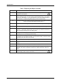
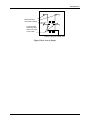
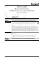
VPR DIN and VRX
Replacement Instructions
VPR DIN 100 Display Assembly (51404680-501)
Kit 4 in User Manual
Document
Number
Form: 57-77-33-17A
Effective: 7-13-00
Supersedes: 8/98
Kit Contents
This kit contains one display assembly.
Summary
This document provides instructions for replacing the display assembly.
WARNING
It is not necessary to remove power before using the button below the
front panel to release the bezel latch, nor before lifting the bezel out of
the way (on its bail linkages) to access the floppy disk used to store
data.
However, disconnect power before using a tool to open the latches on the
plate uncovered when the bezel is lifted out of the way. Opening these latches
provides access to the instrument assembly which slides out of the case. A
potentially lethal shock hazard exists if the instrument assembly is accessed
while powered. More than one switch may be required to disconnect power.
ATTENTION
Installing and replacing assemblies should be done by qualified personnel
only.
This equipment contains devices that can be damaged by electrostatic
discharge (ESD). Use appropriate precautions to avoid damaging the
recorder.
Installation
Procedure
57-77-33-17A
Follow the instructions in Table 1 to replace the display assembly.
1
Kit Instruction
Table 1 Replacing the Display Assembly
Step
2
Action
1
Turn off power to the recorder. More than one switch may be
required to remove power.
2
With the power off open the front of the recorder by pressing the button under the
bezel to release the latch, and then pulling the bezel forward and up. (The bezel is
mounted on bail linkages.) If you press the bottom of the bezel toward the back of
the instrument to compress the gasket slightly, the latch will open easily.
3
Unsnap top bail wire from retainer clips (from chassis side) and lay display forward for
access to the strain relief bracket screws. Figure 1.
4
Loosen 2 screws and swing cable clamp bracket down and away from cable. Figure
1.
5
Unsnap bottom bail wire (from chassis side) and lay display down flat. Figure 1.
6
Disconnect the display end of the ribbon cable between the display assembly and the
recorder. To disconnect, lift both ends of the connector clip. Remove the bail wires
from old display assembly and move display aside.
7
Position the new display assembly flat in front of unit. Snap the bail wires from the
old display into the new display (top and bottom).
8
Thread the cable through the lower bail wire (Figure 1) and insert into the connector
in the back of the new display assembly. (Do not twist the cable.) Secure the cable
by pressing both ends of the connector clip.
9
Snap lower bail wire back into (chassis side) retainer clips.
10
Position the display cable under cable clamp bracket, slide bracket up and tighten
screws.
11
Snap upper bail wire back into (chassis side) retainer clips.
12
Close display by depressing catch, lowering the display to engage the top edge of the
bezel first, then swing in the bottom and press in until the button latch snaps into
place.
13
Do not power up the unit until the display assembly has been replaced
and the display cable has been reconnected
57-77-33-17A
Kit Instruction
Detach bail wire
from plastic chassis
Loosen screws
and swing cable
clamp out of way
to free cable.
Display cable goes through here.
Figure 1 Rear view of display
57-77-33-17A
3
Kit Instruction
Warranty/Remedy
Honeywell warrants goods of its manufacture as being free of defective materials and faulty workmanship.
Contact your local sales office for warranty information. If warranted goods are returned to Honeywell
during the period of coverage, Honeywell will repair or replace without charge those items it finds
defective. The foregoing is Buyer’s sole remedy and is in lieu of all other warranties, expressed or
implied, including those of merchantability and fitness for a particular purpose. Specifications may
change without notice. The information we supply is believed to be accurate and reliable as of this printing.
However, we assume no responsibility for its use.
While we provide application assistance personally, through our literature and the Honeywell web site, it is
up to the customer to determine the suitability of the product in the application.
Sensing and Control
Honeywell
11 West Spring Street
Freeport, IL 61032
57-77-33-17 0700 Printed in USA
www.honeywell.com/sensing