1
F EATU R ES
I
I
I
1
5.?" Large LCD Display
Output Capacity: ?5D‘~r'A [for AC '|Dfl‘r' lnput}{1kVA [for AC ZUUV Input]
Clutput Modes : AC and AC+DC Combined with any ofthe Four Signal Sources
Signal Sources : Internal {INT}, External [EKT}, Internal + External [ADD} and
Sychronization {SYNC}
l Arbitrary Waveform Power Ctutput
I Power Amplifier of External Signal
I Measurement Functions : Voltage, Current, Power, Frequency, Power Factor,
CF, and Harmonic Current
1
o
n
l
1
Capacitor Input Loacl Supported
Sequence Function Allows Programming otfiutput Patterns
Limiter Function {Upper} Lower Limits Function]
30 Sets ofSPNE[RECALL l'u'lemory
Ctutput UnfDfFSwitch
- use russtmcy ancl as-232 Standard for Remote Control
I R |_ bl
|mpy
eta E
APS-i'lI'J2A is not only a precision AC,i"OC power source, but also a powerful analyzer, containing abundant features for the testing and characteristic
analysis ofpower supplies, electronic devices, components and modules. In addition to AC,i'DC power, APS-i ifl2A is fully programmable to
simulate different power outputs. Sequences can be created using arbitrary waveforms as well as voltage or frequency sweeps. Output is divided
into two main operation modes: AC and AC+DC. Each mode can be combined with four signal source modes: internal {INT}, external {EXT},
internal + external [ADO] and external synchronization [S“i’NC} to provide flexible power settings. Voltage, current, power, frequency, load power
Factor, load crest factor and harmonic current output can be monitored in real-time. Even inrush Current can easily be measured during the
power-up ofcapacitive loads. All parameters and values as well as measurement results are displayed simultaneously on the 5.? inch LCD screen.
APS-IIEIZA includes multi functional easy-to-use software that can be used with a USS or RS-232 interface. The software is used to remotely
control panel settings, and to create and edit sequences and arbitrary waveforms. APS-iiI'J2A also has a universal power outlet on the front that
is suitable for most countries as well as output terminal on the rear panel.
The power output function ofAPS-'l'lEl2A includes AC and AC+DC main modes. Each mode can be combined with one ofthe signal sources, including
internal, external, internal + external, and external synchronization, to provide a powerful tool forthe generation ofa power source with abnormal
variations.
Output of Arbitrary Waveforms
Arbitrary waveforms can be edited on the PC and transferred via USE or FtS-232 interface to APS-'l'|ti2A as the internal signal source for power output.
‘IE sets ofwaveform memory with -ilt words waveform length each are available for arbitrary waveform generation and storage.
Amplifier of External Signal
APS-'litl2A can be used as an amplifier forthe external signal to generate output power source. By selecting the external signal source mode {AC-EXT
or AC+DC-EST} and connectthe external signal to the external signal inputfexternal sync signal inputterminal [EXT SIC lN}'E}€T S“i’NC IN}, APS-i'lti2A
generates the power output according to the waveform of the external signal in put.
Power output synchronization with External Signal
The externally synchronized oscillation ofAPS-'| i DEA allows the output power source to be frequency-synchronized with the external signal at Tl'L level in
the frequency range from 4£1Hz to SEIErHz.
B.
l MEASUREMENT FUNCTIONS
APS-1102A is equipped with the following
measurement functions
1
*
‘voltage (PMS, Average DC, Pealt}
Current |[Filv1S, Average DC, Pealt, Pealr hold}
Power |[Effective, Reactive, Apparent}
Synchronization frequency [external synchronization}
Load power factor
Load crest factor
Harmonic current {5iIi,i'El]H: fundamental, up to -itith harmonics}
Q,
Measurement Results and
Measurement of Output
getting i,r3|u,=,5
Harmnnic gum-,,-,1;
SEQUENCE OPERATION
in the Sequence Operation programming, DC, sine waves, square
waves, and TE arbitrary waveforms captured via USEi interface can be
.
used as components for sequence editing. Among the total 255
sequence steps, as maximum capacity, the waveform, level, and time
ti’
-
duration can be set, and constant Ii’ Iteep }’ sweep can be chosen in
.
each individual step. APS-IIIJEA is also equipped with other functions,
_
_
_
.-
_
such as the branching to a specified step during a sequence operation.
All the data of start, stop, or hold ofa sequence operation are saved
irito the sequence memory to perform the Sequence Operation
3'-‘t°"'l3tlF3lli"D,
Step
1
Setting Screen for the Sequence
-5-
.
.
-5- -;-
Step Step
1
1
Step
t
--
Step
-:
5
‘tfoltage Fluctuation Test Pattern
Function [ Set for Each Step }
I APPLICATION FIELDS
1' R S. D and Testing ofwide variety but small quantity power supply
- Used as the power source for relay and switch characteristic testing
manufacturers
I P. St D and Testing ofwide variety and compact consumer device
I Used as the power source for product inspection lines ofdevices in
Wide ‘~’iiFl'-flit’
mflnulaciurfiffi
it Testing of battery-powered modules
- Used as the power source for LCD or lir-Ellliery formation
E,
UNIQUE FEATURES
lnrush Current Measurement and lnrush Current Limiter
For an electronic device containing a capacitor type rectifier, an in rush current, which is larger than the rated current ofthe device, may flow through the
power line immediately after the device is turned on. APS-1 'ltIl2A , with pealt current hold capability, is able to measure this short time inrush current.
On the other hand, the large inrush current flows through the power line may cause the voltage drop, so the electronic device should be able to limit
this effect to a certain extent. APS-‘I i EIZA can supply four times as large peak current as the rated current to support this test.
The output current can be limited by setting the maximum output current{peal-qiaverage current} in advance, so the prototypes can be protected from
abnormal current damage during development evaluation. However, to measure the inrush current ofa completed product, the pealt current limiter
should be set at the maximum value to get a correct measurement result.
Harmonic Current Measurement Function
Switching power sources are widely used in both consumer and industrial electrical products in today's marltet. With the capacitor type rectifier, the
switching power source has its disadvantages using an input AC source carrying significant amount of harmonic current. When a large amount of
harmonic current fiows through the power source line, the switching power supply in the device may experience operation faults caused by the voltage
distortion, which can lead to transformer overheat and possibly result in a hazardous accident. APS-‘I i EIZA includes a harmonic current measuring
function, which can be performed under AC-INT mode at the fundamental wave setting {panel frequency setting} of either 50 Hz or El] Hz. Absolute
values of harmonic current in Rli-‘IS and the harmonic to fundamental ratios up to the -ttith harmonics{2 l<Hz at Stir Hz fundamental}can be measured
and displayed.
F.
APPLICATION EXAMPLES
lr DC to DC converter verification: As in the general environment the input source of DC to DC converter couldn‘t be a perfect DC. It may contain some
AC ripples riding on a DC source due the simple rectifier and filtering circuit used in the consumer products. As ofthis, AC+DC source is used as the
simulation of input power to do the characteristic verification of DC to DC converter.
I Transformer verification: Ideally the voltage fiows through transformer should be a pure AC, however, in the general environment it may also contain
a DC component, which may cause magnetic saturation ofthe transformer and therefore reduce its efficiency. AC +DC source is the simulation of
such power environment.
1' Capacitor verification : The main function of a capacitor is to bloclt the DC voltage and connect the AC voltage in most of the circuits. The DC voltage
imposed on the Capacitor, however, will generate extra heat and gradually degrade the function of the capacitor. AC +DC source could be used to test
the durability and reliability ofa capacitor.
Ir LCD formation : APS-I 102A provides various types ofpower source that suits the application ofthe formation ofLCD panel in the manufacturing
process. The power source could be AC or AC + DC at various levels ofoutput. Formation is an important process to format the liquid crystal cells
inside the panel, so the polarity ofthe crystal cells could be well-arranged to become functional.
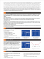
APS-'l'IlZI2A includes a multi-functional and user-friendly software, which supports the remote control ofpanel operations, Sequence editing and execution,
Arbitrary waveform editing and transfer, and Data logging. The remote control software is included to perform the following functions via USS Si. RS-E32
interface;
A. Data logging , B. Sequence editing and execution, C. Arbitrary waveform editing and transfer, D. Remote control of panel operations
‘
,.
|
'
'
- _t.-__t..-. ..
- -| 1-.
‘III -IIII III1i
H
I
I '
IL-iIi-|_IiIi- 1i1n: t.'io
I It-tnunhi ct
1u1 nti
:ri-t-no|Ii1:|:I 11
I": l|_ll
_ IIIIIHIH _1t
i‘l'Ili'IH'\IIIh 1+ :1: ID
1n: . '11
ihfl'I2l'\I'Illll ct
1+ an: III
lII'\II'It'I'I'IlIfl
_-C I
tlli 1.11
In:
111 I'I
:-t:n1 11
nu 1.“Ii 1|
;i|i--1iIitt-|tIi_:1i-t 1+ an: II
ct
an: I11!
I\-I'fi"'IIIlII
ltI-i-int-I-tin: 1+ :u: IH
‘C
I
IIIII nu
:tI-i-to-1:I|--I:|I|
JIH HP
_ not-ti'itIIrt:uti.I 1-I
tur ltll
tut-tiu|trt:1|1 qt
;ItiI-ti-;-11-int.-t 1+ rue I'ct
an:
i.o
I\Ifl'!H""IIl!I
:1 :u: 1
fl'l'H'H.I"'|flD
ta
.
I: it it I
1- '
I‘
-1-11
t.'\1i
.i.u
4._-I
1eItI
I :1I
-ctli
i:-1i
up
Ill
.111
-III
-1 n
- ll
in 1-»...
:-t:- t:
tit:- 11r||' ll
III 1It- t- t-:
I‘I'
1|
1|
4|
4-t
1t
ip-1-or
:iI
tt1
til
t.u
1'
r
:tIt:-
1.
1
1
-3
lll
III
I
I
1
an
-II
Ill
no
i.'\1i
All
I4'!
1:1u1i
I.
-it
1
tlt
'
|'
at
I
1
t.
', Ii
'———\
-—F-l"'r1.-.--1-i1-.-.+in-i-
__ '
.
I:i-i.it|i-.1lit-1- 14:14;
-'
.,__
"
t
.,_‘t,___,_'_
I
--it --.--
eti.-|1.-In-.p
*-1‘
_
1'
I-to-t-t
__
. 1-3-rI,I
..
I ' III .na Ii.i ll; I 4.1 - .-1-A.
_
;\-qw
‘ll l
"
C
_- .-
""
.
'
-,i,. I_;|_,.1 1
, ,;,,,"
|;|-tug
l ;.,.,,,,
“M -_
raves
.___ -
_
mm .;,_,._. -.-__-|.,_ii.,- CH
"'I--‘ll-I-"\-I on-1
- III-rII-rt I=-I-I-I-=- til, ixoxosd, 1..-1'-'r:It.\ tteve
“H
III
t:It.1|1.1t1-t- 1.;|;i:.|,-|It-iq-.1!-1IiIi¢
A1
-I
i' "I
" “F
I
-
‘SS’
l1'-
""‘
-'
"C-—"Il--I
'-'4 """"'
I
‘II
I
i|i._
Ir?
I1
1-
I
11t out
1o
1t
ti
A. Logging of ivleasurement iillalues
C- II __-
'b'l|—-Ir
n__‘
-I-rt
Mod-ly
“
--.
oqu-r-i|t
I;n.|
a
t:_i;Ii.r
- pi:-tI.'
liIi|i-+I1Ii.tI-t-t-II1-III-|
11r
J T .-.
+-.-
5 rt ' '
ii
I11
In
t
r
c- .I'-:
Il."|'
J1‘ -p.-1It.ill
o- rt
-ole
I5;
ill
i..-
ti--1|-t-I-raoli-qr-1|-t
H
E-I.-I-an -iIu
fll-D '-I
uH+:_|
"£11-.t"o
-_.
<-~
1IIt -I-I
-1Iitti.t|t|1-.|l-.|1
:7’. kn,“
iI I H r Iii“
in-1---iI
1-1.1
.-1.-11
B. Sequence Editing
E-:t-|:--1-tel
i
u‘
i--I
-- I-I
C. Creation of Arbitrary Waveform
-~= :1-i:
I-_-.--ta-1-..
“I
d
I
..-.t...--.-
O. Remote Control Screen
I
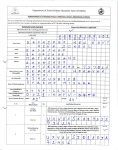
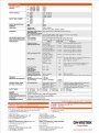
SPECIFICATIONS
AC
CAPACITY
input {ltlu -. iaev]
input {1S0 ~ astrv]
DC input titre -. iaevi
input {1S0-- astiv]
rstiva
1000‘vA
rstivr
iixxivr
OUTPUT 'vOLTAGE
AC
OUTPUT MAI-‘(I MUM PEAK
CURRE NTS
10011‘
2001*’
DC 1001*’
2001f
AC 1001!
2001*’
DC 1001i‘
2001'
10011’
1001?
aav ~ 1SS.0vrms
0.0"v' - 310.0‘vrms
-aao.ov~+aao.ov
-I!l=l0.0"r'~+Ii=l0.0"r'
10A
SA
10A
SA
=i0ApIt
EOApIt
FREQUENCY
Setting Range
1.01-lz~5S0.0Hz
-ti:i.i:iirs ofset{1.0Hz~SS0.0Hz,2SzS“C}
MAXIMUM OUTPUT
OUTPUT MAI. CURRENT
Setting Aocuracy
WAYE FORM
SINE WAYE, SQUARE WAYE, When signal source mode is INT and ADD mode only
AR EITRARY wave
[Up To 16 Typw Cap Be Saved}
0.5% MA1iI{SOHafEOHa}, iS0‘i‘i3 or higher of the rated output voltage,
Output ‘voltage Distortion
Rate
the maximum current or lower ; THD+N
LINE ‘VOLTAGE REGLIl.ATlON
LOAD YOLTAGE REGULATION
Power input voltage iaov,r1 2011;’13 0111 no load ,rated output
0.2% MA‘-CIMUM
0.5% MARIMUM
At output terminal under np load and rayed resistance load
RANGE
RESOLUTION
ACCURACY
1.0 ~ 550.0 Hz
it 421-Iz-455 H z
u caie '|00v:2S0.0‘vrrns
0.1 I-tz
0.01 as ofset {I .0Hz~SS0.0Hz,2S=i=S°Cl
0.1‘v'rrns
i{0.S S1 of rd g+0.3'vrm slj at Sine ST
MEASUREMENT
Frequency Counter
RMS ‘volt-It-1eter{AC+DC}
Fu S cae 100'v:S0I0.0‘v'rms
At DC -i0Hz-SSOI-iz
S cae 100"v':2S0.0‘v'rms
0.1 vrms
S cale 2ii0v:S00.0‘vrms
0.1 vrms
0.1vrrris
i{0.? SS of rd g+0.9‘vrm s}i; at 231 5°C
i{0.F as of rd g+1 .S‘v'rm sl; at 231511
Sca e 1 S.00Arms
0.01Arms
i0.SSS of rdg+0.0=tArms rat 23eS‘iIj
0.01 Arms
1W
i0.?S5 of rd g+0.0SArms ,' at 23-15°C Output Current is
SSS~100Sti ofthe Maximum Current
ta-at ofrdg+1W {at ESti:S°C
1W
t3Sr='E- ofrdg+i2‘vi' ; at23eS"if;50v or higher output
RMS Amp-Meter{AC+DC}
as Hz- SS1-Iz
‘Wattage Meter
DC I‘-I0Hz-SS0Hz
Sca e 1S.00Arms
45 Hzn-SSH:
Sca e 1200W
DC
Sca e 1 200W
“I1_I'l_l'I_I'I_I
9:29:-"3?-CEERCE 'l'I-"I
Load Power Factor
t{0.S 96 of rdg+0.S‘vrms}; at 2S=tS"C
voltage, output current is 1096 to 10095 of the
0.00 ~ 1.00
0.01
Load Crest Factor
Measurement
External Synchronization
0.00 ~ S0.00
0.01
Fre_quency Measurement
Phase When Output ls On
3S.0Hz- S2S.0Hz
0.0“-= 359.91“
maximum current
Measurement
PROGRAM
{SEOU EN CE PROG RAMMING}
i0.2Hz; at 23=i=S°C
0.1Hz
0.1
Memory
1-30 Sets
Step Range{Eacli Memory Set} 1-SSS Step
0.00-01 S ~ 999.9999 S
Step Time Setting
When signal source mode is INT and ADD mode only
0.0001 S
{=0.1mS}
EXTERNAL sicNAL INPUT
{sxr Mode , aoo Mode}
Cain Setting Range
OUTPUT MODE
AC - INT Mode
10'0‘v range 0~220.0 times
{Initial ‘value 100 0}
zoov range 0--4110.0
' ' times
{Initial ‘value E00 0}
AC + DC - INT Mode
0.1
0.1
AC - ADD Mode
POWER CO NSUM PTION_lFACTOR
INTERFACE
DIMENSIONS E WEIGHT
assivn x train} x rII‘I0{D} ;Appr‘ox. s.r Itg
POWER SOURCE
i SSS {DC or ItSHz to SSH: , gain is at initial value,
with the rated voltage output, no load}
AC + DC - ADD Mode
AC - EST Iviode AC + DC - EXT Ivlode AC - SYNC l'vl ode
Save,tRecaI| 90 sets
AC100'v ~ 2.i0‘v i109S ; SOHz ,i' t-i0Hx t2Hx {Signal Phase}
1.-il<‘vA max ,i' 0.9Smin {AC100v]i ; 0.9min {AC20ItTv}
MEMO RY
i S96 {DC or 4SHz to SSH: , gain is at initial value,
with the rated voltage output, no load}
AC + DC - SYNC Mode
USI-1{USBTl"vlC} at as-ass Standard
Specifications subject to change without notice.
1213.] ‘| ii]-1,tI,-ii; [J1 Bi-t
OPTIONAL AOI: ESSO RIES
ORDERING INFORMATION
APS-110."-EA 1|-ivA Programmable AC_iDC Power Source
ACCESSORIES
GTL-E34
User Manual x 1, Power Cord x 2, {1SA,'12Sv ;Em ;for}apan}{10A,t2S0v;
l.Sm without plug, forjapan, North America, and Europe only},
CD-ROM {Remote Control Software} x1
RS231 Cable
FREE DOWN LOAD
Remote Control Software
Lab‘view Driver
Global Headquarters
l_l.S.A. Subsidiary
GOOD WILL INSTRUMENT CO., LTD.
INSTER AMERICA CORP.
T -i-SSE-2-2 2E-S-03 S9 F +335-2-2263-0639
E-rriail: mart-:etingtg2igoodwi|l.com.tv.I
T +1-909-5913953 F -i-1-909-5912230
E-mail: sa|est_§3iinsteIramerica.com
China Subsidiary
japan Subsidiary
GOOD WILL INSTRUMENT {SUZHOU} CO., LTD.
TEXIO TECH NOLOOY CORPORATION.
T +SEI-S12-ti-ti-IS-1-S"1I-*1-* F +1'S-EII-EIII-DOECI-REF?
E-mail; ma rlcetingifil-ir1stIeIt.r:i;ir'ri.ct'i
T +31-AIS-I520-2303 F -i-S1 PISS-S S4-1'1 SI
E-mail: infoifi]-texio.co.jp
Malaysia Subsidiary
Korea Subsidiary
GOOD WI LL INSTRUMENT {M} SDN. EH D.
T +su4-E-3-passe F +soa-srossss
GOOD WILL INSTRUMENT I"-IOREA CO., LTD.
T +az-2-3139-azus F ea:-2-3139-aztir
E-l"r‘| ail: r,;.siIe*,;i;§2igi:i-ciIcl'ir.rilI.i:.-i:i~r't‘t.r'ri}|r
E-rriail : g_'IrrinsteIri,'§;‘i-girrinste I=:.-cc:-,IItr
w
G
K
W
sllT|PI}' Reliable
www.gwinstek.com


![j:j_"Xt$l"j:]:":,lg]:"r/Human Resources have been duty - e](http://vs1.manualzilla.com/store/data/005657435_1-26d97049bf04f0fd92265d73e45a9ab3-150x150.png)