1
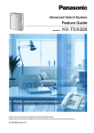
Advanced Hybrid System
Installation Manual
Model
KX-TEA308
KX-TEB308
Thank you for purchasing a Panasonic Advanced Hybrid System.
Please read this manual carefully before using this product and save this manual for future use.
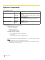
System Components
System Components Table
Model
Main Unit
Optional Service Cards
Proprietary Equipment
*1
Description
KX-TEA308
Advanced Hybrid System: 3 Outside (CO) Lines, 8 Hybrid
Extensions
KX-TEB308
Advanced Hybrid System: 3 Outside (CO) Lines, 4 Hybrid
and 4 SLT Extensions*1
KX-TE82460
2-Port Doorphone Card
KX-TE82492
2-Channel Voice Message Card (for KX-TEA308 only)
KX-TE82493
3-Port Caller ID Card
KX-T30865
Doorphone
KX-A227
Backup Battery Cable
Taiwan: 4 PT Extensions
For supported extension types, refer to "2.5.1 Connecting Extensions".
Abbreviations in this manual
Proprietary Telephone: PT
Single Line Telephone: SLT
Direct Station Selection: DSS
Compatible Proprietary Telephones
•
KX-T7700, KX-T7300, and KX-T7000 series PTs
•
KX-T7710 SLT
•
KX-T7740, KX-T7340, and KX-T7040 DSS Consoles
For the equipment that can be connected to the PBX, refer to "1.2.2 System Connection Diagram".
Notice
Certain models may not be available in your country/area.
Certain PTs and features may not be available in your country/area. Consult your certified
Panasonic dealer for more information.
2
Installation Manual
Important Safety Instructions
When using your telephone equipment, basic safety precautions should always be followed to reduce
the risk of fire, electric shock and injury to persons, including the following:
1. Read and understand all instructions.
2. Follow all warnings and instructions marked on the product.
3. Unplug the product from the wall outlet before cleaning. Do not use liquid cleaners or aerosol
cleaners. Clean with a damp cloth.
4. Do not use this product near water, for example, near a bathtub, wash bowl, kitchen sink, or
laundry tub, in a wet basement, or near a swimming pool.
5. Do not place the product on an unstable surface, as a fall may cause serious internal damage.
6. Slots and openings in the front, back and bottom of the cabinet are provided for ventilation; to
protect it from overheating, these openings must not be blocked or covered. The openings should
never be blocked by placing the product on a bed, sofa, rug, or other similar surface while in use.
The product should never be placed near or over a radiator or other heat source. This product
should not be placed in a sealed environment unless proper ventilation is provided.
7. The product should only be connected to the type of electrical power supply specified on the
product label. If you are not sure of the type of power supply to your home, consult your dealer
or local power company.
8. For safety purposes this unit is equipped with an earthed plug. If you do not have an earthed
outlet, please have one installed. Do not bypass this safety feature by tampering with the plug.
9. Do not allow anything to rest on the power cord. Do not locate this product where the power cord
may be stepped on or tripped on.
10. To reduce the risk of fire or electric shock, do not overload wall outlets and extension cords.
11. Do not insert objects of any kind into this product through its slots and openings, as they may
touch dangerous voltage points or short out parts that could result in a risk of fire or electric
shock. Never spill liquid of any kind on or in the product.
12. To reduce the risk of electric shock, do not disassemble this product. Only qualified personnel
should service this product. Opening or removing covers may expose you to dangerous voltages
or other risks. Incorrect reassembly can cause electric shock.
13. Unplug this product from the wall outlet and have it serviced by qualified service personnel in the
following cases:
a)
b)
c)
d)
When the power supply cord or plug is damaged or frayed.
If liquid has been spilled into the product.
If the product has been exposed to rain or water.
If the product does not operate according to the operating instructions. Adjust only the
controls that are explained in the operating instructions. Improper adjustment of other
controls may result in damage and may require service by a qualified technician to restore
the product to normal operation.
e) If the product has been dropped or the cabinet has been damaged.
f) If product performance deteriorates.
14. Avoid using wired telephones during an electrical storm. There is a remote risk of electric shock
from lightning.
15. Do not use a telephone in the vicinity of a gas leak to report the leak.
SAVE THESE INSTRUCTIONS
Installation Manual
3
Precautions
•
Keep the unit away from heating appliances and devices that generate electrical noise such as
fluorescent lamps, motors and televisions. These noise sources can interfere with the
performance of the PBX.
•
This unit should be kept free of dust, moisture, high temperature (more than 40 ˚C ) and
vibration, and should not be exposed to direct sunlight.
If you are having problems making calls to outside destinations, follow this procedure to test the
outside (CO) lines:
•
1. Disconnect the PBX from all outside (CO) lines.
2. Connect known working single line telephones (SLTs) to those outside (CO) lines.
3. Make a call to an external destination using those SLTs.
•
If a call cannot be carried out correctly, there may be a problem with the outside (CO) line that
the SLT is connected to. Contact your telephone company.
If all SLTs operate properly, there may be a problem with your PBX. Do not reconnect the PBX
to the outside (CO) lines until it has been serviced by an authorised Panasonic Factory Service
Centre.
Wipe the unit with a soft cloth. Do not clean the unit with abrasive powders or with chemical
agents such as benzene or thinner.
For users in New Zealand only
•
This equipment shall not be set to make automatic calls to the Telecom '111' Emergency Service.
•
The grant of a Telepermit for any item of terminal equipment indicates only that Telecom has
accepted that the item complies with minimum conditions for connection to its network. It
indicates no endorsement of the product by Telecom, nor does it provide any sort of warranty.
Above all, it provides no assurance that any item will work correctly in all respects with another
item of Telepermitted equipment of a different make or model, nor does it imply that any product
is compatible with all of Telecom's network services.
•
This equipment is not capable, under all operating conditions, of correct operation at the higher
speeds for which it is designed. Telecom will accept no responsibility should difficulties arise in
such circumstances.
•
Some parameters required for compliance with Telecom's Telepermit requirements are
dependent on the equipment (PBX) associated with this modem. In order to operate within the
limits for compliance with Telecom's Specifications, the associated PBX equipment shall be set
to ensure that modem calls are answered between 3 and 30 seconds of receipt of ringing.
•
IMPORTANT NOTICE
Under power failure conditions, the connected telephones may not operate. Please ensure that
a separate telephone, not dependent on local power, is available for emergency use.
For users in Australia only
•
No External TRC Terminal is provided due to an Internal Link between PE and TRC.
For users in Taiwan only
•
Lithium batteries can be found in the circuit boards of the main board and optional cards of the
PBX.
4
Installation Manual
Notes
•
•
When disposing of any of the above products, all batteries must be removed. Follow the
applicable laws, regulations, and guidelines in your country/area regarding disposal of
batteries.
When replacing a battery, use only the same battery type, or an equivalent recommended
by the battery manufacturer.
Notice
Regarding removing or replacing a battery in the circuit board, consult your dealer.
For users in Finland, Norway and Sweden only
•
This unit may only be installed in a room or space with restricted access, and equipotential
bonding must be applied. For information on earthing, refer to "2.2.5 Connecting Frame Earth".
WARNING
•
•
•
•
•
•
THIS UNIT MAY ONLY BE INSTALLED AND SERVICED BY QUALIFIED
SERVICE PERSONNEL.
IF DAMAGE TO THE UNIT EXPOSES ANY INTERNAL PARTS, DISCONNECT
THE POWER SUPPLY CORD IMMEDIATELY AND RETURN THE UNIT TO YOUR
DEALER.
UNPLUG THIS UNIT FROM THE AC OUTLET IF IT EMITS SMOKE, AN
ABNORMAL SMELL OR MAKES UNUSUAL NOISE. THESE CONDITIONS CAN
CAUSE FIRE OR ELECTRIC SHOCK. CONFIRM THAT SMOKE HAS STOPPED
AND CONTACT AN AUTHORISED PANASONIC FACTORY SERVICE CENTRE.
WHEN RELOCATING THE EQUIPMENT, FIRST DISCONNECT THE TELECOM
CONNECTION BEFORE DISCONNECTING THE POWER CONNECTION. WHEN
THE UNIT IS INSTALLED IN THE NEW LOCATION, RECONNECT THE POWER
FIRST, AND THEN RECONNECT THE TELECOM CONNECTION.
TO PREVENT POSSIBLE FIRE OR ELECTRIC SHOCK, DO NOT EXPOSE THIS
PRODUCT TO RAIN OR MOISTURE.
THE POWER SUPPLY CORD IS USED AS THE MAIN DISCONNECT DEVICE.
ENSURE THAT THE AC OUTLET IS LOCATED NEAR THE EQUIPMENT AND IS
EASILY ACCESSIBLE.
CAUTION
DANGER OF EXPLOSION EXISTS IF A BATTERY IS INCORRECTLY REPLACED. REPLACE
ONLY WITH THE SAME OR EQUIVALENT TYPE RECOMMENDED BY THE BATTERY
MANUFACTURER. DISPOSE OF USED BATTERIES ACCORDING TO THE
MANUFACTURER'S INSTRUCTIONS.
Installation Manual
5
For Future Reference
Please print, record, and retain the following information for future reference.
Note
The serial number of this product can be found on the label affixed to the unit. You should record
the model number and the serial number of this unit as a permanent record of your purchase to
aid in identification in the event of theft.
MODEL NO.
SERIAL NO.
DATE OF PURCHASE
NAME OF DEALER
DEALER'S ADDRESS
DEALER'S TEL. NO.
The KX-TEA308E, the KX-TEA308NE, the KX-TEA308GR, the KX-TEA308CE,
and the KX-TEA308PD are designed to interwork with the Analogue Public
Switched Telephone Network (PSTN) of European countries.
Panasonic Communications Co., Ltd./Panasonic Communications Company (U.K.) Ltd. declares that
this equipment is in compliance with the essential requirements and other relevant provisions of Radio
& Telecommunications Terminal Equipment (R&TTE) Directive 1999/5/EC.
Declarations of Conformity for the relevant Panasonic products described in this manual are available
for download by visiting:
http://doc.panasonic.de
Contact:
Panasonic Services Europe GmbH
Panasonic Testing Centre
Winsbergring 15, 22525 Hamburg, F.R. Germany
6
Installation Manual
Introduction
About the Installation Manual
This Installation Manual is designed to serve as an overall technical reference for Panasonic
Advanced Hybrid System, KX-TEA308 and KX-TEB308. It explains how to install the hardware and
programme this PBX using KX-TE308 Maintenance Console.
The Installation Manual is divided into the following sections:
Section 1 System Outline
Provides general information on the PBX, including the system capacity and specifications.
Section 2 Installation
Provides detailed instructions for installing the PBX, optional service cards, and peripheral
equipment.
Section 3 Guide for KX-TE308 Maintenance Console
Explains how to install and use KX-TE308 Maintenance Console, a PC-based programming
utility.
Section 4 Troubleshooting
Provides information on troubleshooting and restarting the PBX.
About the Other Manuals
The following manuals are also available:
Feature Guide
Explains what the PBX can do, as well as how to obtain the most of its many features and
facilities.
User Manual
Describes how users can access commonly used features and functions with proprietary
telephones (PTs), single line telephones (SLTs), and Direct Station Selection (DSS) Consoles.
Trademarks
•
•
•
•
Microsoft and Windows are either registered trademarks or trademarks of Microsoft
Corporation in the United States and/or other countries.
Celeron and Intel are trademarks or registered trademarks of Intel Corporation or its
subsidiaries in the United States and other countries.
All other trademarks identified herein are the property of their respective owners.
Screen shots reprinted with permission from Microsoft Corporation.
Installation Manual
7
Precautions for Users in the United Kingdom
FOR YOUR SAFETY, PLEASE READ THE FOLLOWING TEXT CAREFULLY.
This appliance is supplied with a moulded three-pin mains plug for your safety and convenience. A 5
amp fuse is fitted in this plug. Should the fuse need to be replaced, please ensure that the
replacement fuse has a rating of 5 amps and that it is approved by ASTA or BSI to BS1362.
Check for the ASTA mark
or the BSI mark
on the body of the fuse.
If the plug contains a removable fuse cover, you must ensure that it is refitted when the fuse is
replaced. If you lose the fuse cover, the plug must not be used until a replacement cover is obtained.
A replacement fuse cover can be purchased from your local Panasonic dealer.
IF THE FITTED MOULDED PLUG IS UNSUITABLE FOR THE AC OUTLET IN YOUR PREMISES,
THEN THE FUSE SHOULD BE REMOVED AND THE PLUG CUT OFF AND DISPOSED OF
SAFELY. THERE IS A DANGER OF SEVERE ELECTRICAL SHOCK IF THE CUT-OFF PLUG IS
INSERTED INTO ANY 13 AMP OUTLET.
If a new plug is to be fitted, please observe the wiring code as shown below. If in any doubt, please
consult a qualified electrician.
WARNING
THIS APPLIANCE MUST BE EARTHED.
IMPORTANT: The wires in the mains lead are coloured as follows:
Green-and-yellow: Earth
Blue: Neutral
Brown: Live
As the colours of the wires in the mains lead of this apparatus may not correspond with the coloured
markings identifying the terminals in your plug, proceed as follows.
The wire that is coloured GREEN-AND-YELLOW must be connected to the terminal in the plug that
is marked with the letter E or by the safety earth symbol
or coloured GREEN or GREEN-ANDYELLOW.
The wire that is coloured BLUE must be connected to the terminal that is marked with the letter N or
coloured BLACK.
The wire that is coloured BROWN must be connected to the terminal that is marked with the letter L
or coloured RED.
8
Installation Manual
How to replace the fuse: Open the fuse compartment with a screwdriver and replace the fuse and
fuse cover.
The equipment must be connected to direct extension lines, and a payphone should not be connected
as an extension.
999 and 112 can be dialled on the apparatus after accessing the Exchange line for the purpose of
making outgoing calls to the BT emergency services.
During dialling, this apparatus may tinkle the bells of other telephones using the same line. This is not
a fault and we advise you not to call Fault Repair Service.
Installation Manual
9
Table of Contents
1
System Outline ..................................................................................... 13
1.1
1.1.1
1.2
1.2.1
1.2.2
1.3
1.3.1
1.3.2
1.3.3
2
Installation............................................................................................. 21
2.1
2.1.1
2.2
2.2.1
2.2.2
2.2.3
2.2.4
2.2.5
2.2.6
2.2.7
2.2.8
2.3
2.3.1
2.3.2
2.3.3
2.3.4
2.4
2.4.1
2.5
2.5.1
2.5.2
2.6
2.6.1
2.7
2.7.1
2.8
2.8.1
2.9
2.9.1
2.10
2.10.1
3
Before Installing ..............................................................................................................22
Before Installing ................................................................................................................22
Installing the Advanced Hybrid System........................................................................24
Unpacking .........................................................................................................................24
Names and Locations .......................................................................................................25
Opening/Closing Covers ...................................................................................................26
Securing the Cables.......................................................................................................... 29
Connecting Frame Earth ...................................................................................................31
Connecting Backup Batteries............................................................................................32
Wall Mounting ................................................................................................................... 34
Installing Surge Protector..................................................................................................37
Installing Optional Service Cards..................................................................................40
Location of Optional Service Cards ..................................................................................40
3-Port Caller ID Card (KX-TE82493).................................................................................41
2-Port Doorphone Card (KX-TE82460).............................................................................43
2-Channel Voice Message Card (KX-TE82492) ...............................................................44
Connecting Outside (CO) Lines.....................................................................................46
Connecting Outside (CO) Lines ........................................................................................46
Connecting Extensions ..................................................................................................47
Connecting Extensions .....................................................................................................47
Connecting Extensions in Parallel.....................................................................................49
Connecting Doorphones and Door Openers................................................................ 50
Connecting Doorphones and Door Openers.....................................................................50
Connecting Doorbell or Door Chime.............................................................................54
Connecting Doorbell or Door Chime .................................................................................54
Connecting Peripherals..................................................................................................55
Connecting Peripherals .....................................................................................................55
Power Failure Connections ............................................................................................59
Power Failure Connections ............................................................................................... 59
Starting the Advanced Hybrid System..........................................................................60
Starting the Advanced Hybrid System ..............................................................................60
Guide for KX-TE308 Maintenance Console ........................................ 63
3.1
3.1.1
3.2
10
System Highlights........................................................................................................... 14
System Highlights .............................................................................................................14
Basic System Construction ...........................................................................................15
Main Unit ...........................................................................................................................15
System Connection Diagram ............................................................................................16
Specifications..................................................................................................................17
General Description .......................................................................................................... 17
Characteristics ..................................................................................................................18
System Capacity ...............................................................................................................19
Installing KX-TE308 Maintenance Console...................................................................64
Installing KX-TE308 Maintenance Console on a PC.........................................................64
Connection ......................................................................................................................66
Installation Manual
3.2.1
3.2.2
3.2.3
4
Connection ....................................................................................................................... 66
Starting KX-TE308 Maintenance Console for the first time.............................................. 69
Accessing PBX via Internal Modem ................................................................................. 70
Troubleshooting ....................................................................................73
4.1
4.1.1
4.1.2
4.1.3
4.1.4
4.1.5
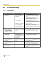
Troubleshooting ............................................................................................................. 74
Installation ........................................................................................................................ 74
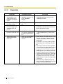
Connection ....................................................................................................................... 75
Operation.......................................................................................................................... 76
System Restart................................................................................................................. 77
System Reset with System Data Clear ............................................................................ 78
Index ............................................................................................................79
Installation Manual
11
12
Installation Manual
Section
1
System Outline
This section provides general information on the Advanced
Hybrid System, including system capacity and specifications.
Installation Manual
13
1.1 System Highlights
1.1
System Highlights
1.1.1
System Highlights
Built-in Voice Message (BV) (Optional voice message card required) (KX-TEA308 only) Built-in Voice Message (BV) allows a caller to leave a voice message in a user's personal message
area or the PBX's common message area.
Fixed Line SMS Terminal Support (Optional Caller ID card required) The PBX can relay incoming calls from a Short Message Service (SMS) centre to specific single line
telephones (SLTs) that support SMS. Fixed Line SMS is a service that allows text messages to be
sent and received via Public Switched Telephone Network (PSTN) access. We recommend using
SMS-enabled Panasonic SLTs.
Caller ID Display on SLT (Optional Caller ID card required) The PBX can receive Caller ID information (telephone numbers and callers' names) from calls
received on outside (CO) lines. This information can be shown on the displays of SLTs that support
Caller ID as well as proprietary telephones (PTs) when receiving calls.
3-level Automated Attendant (AA)
3-level Automated Attendant (AA) service allows a caller to dial a single-digit number (Direct Inward
System Access [DISA] AA number) following the guidance of 3-level DISA outgoing messages
(OGMs), and be connected to the desired party automatically.
PC Programming
System programming settings can be accessed using a PC and the Panasonic KX-TE308
Maintenance Console software as well as by using a PT. The PBX software can be upgraded via the Serial Interface (RS-232C port) or USB port, using the
KX-TE308 Maintenance Console software.
Quick Setup
Basic PBX parameters such as Automatic Configuration for Outside (CO) Line Type, Country Setting
can be programmed the first time the PBX is accessed with a PC using the KX-TE308 Maintenance
Console software.
Advanced Hybrid System
This PBX supports the connection of PTs, Direct Station Selection (DSS) Consoles and single line
devices such as SLTs, fax machines, wireless telephones and data terminals.
14
Installation Manual
1.2 Basic System Construction
1.2
Basic System Construction
1.2.1
Main Unit
The KX-TEA308 and KX-TEB308 have a capacity of 3 outside (CO) lines and 8 extensions. It is
capable of supporting Panasonic proprietary telephones (PTs), and single line devices such as single
line telephones (SLTs), fax machines and data terminals.
To expand its capabilities, the PBX can be equipped with optional components or user-supplied
peripherals, such as door openers, external speakers, and an external audio source such as a radio
or CD player.
Note
For supported extension types, refer to "2.5.1 Connecting Extensions".
Installation Manual
15
1.2 Basic System Construction
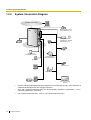
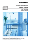
1.2.2
System Connection Diagram
Outside (CO) Line
Remote PC
External audio source
(radio, CD player, etc.)
Paging system
(loudspeaker, amplifier
and speaker, etc.)
Batteries
SLT
PT
Door Opener/
Doorbell/Door Chime
Fax/Telephone
Answering Machine
Doorphone
DSS Console
PC
Wireless Phone
Printer
•
•
•
16
PC
Voice Processing
System
Connect a display-equipped proprietary telephone (PT) to extension jack 01, as this extension is
automatically designated as the manager extension.
A PT and a single line telephone (SLT) can be connected in parallel to a Hybrid Port. (o 2.5.2
Connecting Extensions in Parallel)
For supported extension types, refer to "2.5.1 Connecting Extensions".
Installation Manual
1.3 Specifications
1.3
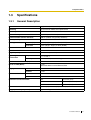
Specifications
1.3.1
General Description
Control Bus
Original bus (16-bit, 24 MHz)
Switching
Space Division CMOS Crosspoint Switch
Power Input
100 V AC to 240 V AC, 0.8A to 0.4A, 50 Hz/60 Hz
External Battery
+24 V DC (+12 V DC × 2)
Maximum Power Failure Tolerance
300 ms (without using backup batteries)
Memory Backup Duration
7 years
Dialling
Outside (CO) Line
Pulse (10 pps, 20 pps) or Tone (DTMF)
Extension
Pulse (10 pps, 20 pps) or Tone (DTMF)
Intercom Path
3
Mode Conversion
Pulse-DTMF
Ring Frequency
20 Hz/25 Hz (selectable)
Operating
Environment
Temperature
0 ˚C to 40 ˚C
Humidity
10 % to 90 % (non-condensing)
Conference Call Outside (CO) Line
2
Music on Hold (MOH)
1 port
Selectable MOH: Internal/External/Tone
Paging
Serial Interface Port
Internal
1
External
1 port
RS-232C
1
USB 1.1
1
Extension Connection Cable
SLT
1-pair wire (T, R)
PT
2-pair wire (T, R, H, L)
DSS Console
1-pair wire (H, L)
Dimensions
249 mm (W) × 316 mm (H) × 73 mm (D)
Weight (when fully expanded)
Approx. 1.8 kg
Installation Manual
17
1.3 Specifications
1.3.2
Characteristics
Terminal Equipment Loop Limit
PT
40 :
SLT
600 : including set
Doorphone
20 :
Minimum Leakage Resistance
15 000 : minimum
Maximum Number of Extension
Instruments per Line
1 PT or SLT in standard connection
1 PT and 1 SLT in parallel connection
Ring Voltage
75 Vrms at 20 Hz/25 Hz depending on the ringing load
Outside (CO) Line Loop Limit
1600 : maximum
Hookswitch Flash/Recall Timing
Range
24 ms–2032 ms
Door Opener Current Limit
30 V DC/30 V AC, 3 A maximum
Paging Terminal Impedance
600 :
MOH Terminal Impedance
10 000 :
18
Installation Manual
1.3 Specifications
1.3.3
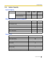
System Capacity
System Capacity
TEA308
TEB308
TEB308TW
Outside (CO) lines
3
3
3
Extensions for PT/SLT
8
4
4
Extensions for SLT only
—
4
—
Extensions for PT only
—
—
4
TEA308
TEB308
PT and SLT
16
12
2-Port Doorphone Card
1
1
2-Channel Voice Message Card (for KX-TEA308 only)
1
—
Doorphone
2
2
Door Opener
2
2
Pager
1
1
Music on Hold (MOH)
1
1
DSS Console
2
2
Basic System
Maximum Cards and Terminal Equipment
Item
System Data
Item
Operator
System Speed Dialling
One-touch Dialling
Personal Speed Dialling
Max. Quantity
1
100
24 per extension (PT)
10 per extension
Call Park Area
10
Absent Message
6
Toll Restriction (TRS) COS
5
Extension Group
8
Message Waiting
8 per extension
Message for Built-in Voice Message (KX-TEA308 only)
125 messages (total 60 minutes)
Installation Manual
19
1.3 Specifications
20
Installation Manual
Section
2
Installation
This section describes how to install the Advanced Hybrid
System. Detailed instructions for installing the main unit and
optional service cards, and cabling of peripheral equipment
are provided. Information on system expansion and peripheral
equipment installation is included.
Installation Manual
21
2.1 Before Installing
2.1
Before Installing
2.1.1
Before Installing
Please read the following notes concerning installation and connection before installing the PBX and
terminal equipment. Be sure to comply with all applicable laws, regulations, and guidelines.
Safety Installation Instructions
When installing telephone wiring, basic safety precautions should always be followed to reduce the
risk of fire, electric shock and injury to persons, including the following:
1. Never install telephone wiring during a lightning storm.
2. Never install telephone jacks in wet locations unless the jack is specifically designed for wet
locations.
3. Never touch uninsulated telephone wires or terminals unless the telephone line has been
disconnected at the network interface.
4. Use caution when installing or modifying telephone lines.
Installation Precautions
This PBX is designed for wall mounting only, and should be installed in a location where it is
accessible for inspections and maintenance.
To prevent malfunction, noise, or discolouration, avoid installing the PBX in the following locations:
1.
2.
3.
4.
5.
6.
In direct sunlight and hot, cold, or humid places. (Temperature range: 0 ˚C to 40 ˚C )
Areas where sulfuric gases may be present, such as near thermal springs.
Areas where shocks or vibrations are frequent or strong.
High-dust areas, or places the PBX may come into contact with water or oil.
Near devices that generate high frequencies, such as sewing machines or electric welders.
On or near computers, telexes, or other office equipment, as well as microwave ovens or air
conditioners. (It is preferable not to install the PBX in the same room as the above equipment.)
7. Within 1.8 m of radios and televisions. (Both the PBX and Panasonic proprietary telephones
should be at least 1.8 m away from such devices.)
8. Locations where other objects will obstruct the area around the PBX. Be especially careful to
leave at least 20 cm of space above and 10 cm to the sides of the PBX for ventilation.
Wiring Precautions
Be sure to follow these instructions when wiring the unit:
1. Do not run unshielded telephone cables near AC power cables, computer cables, AC power
sources, etc. When running cables near other noise-generating devices or cables, use shielded
telephone cables or shield the telephone cables with metal tubing.
2. If cables are run on the floor, use protectors to prevent the cables from being stepped on. Avoid
running cables under carpets.
3. Avoid using the same AC outlet for computers, telexes, and other office equipment, as noise
generated by such equipment may hamper system performance or interrupt the system.
22
Installation Manual
2.1 Before Installing
4. Use 2-pair telephone cables when connecting Panasonic proprietary telephones (PTs).
Use 1-pair telephone cables when connecting single line telephones (SLTs), data terminals,
answering machines, computers, voice processing systems, etc.
5. Unplug the PBX from its power source when wiring, and plug the PBX back in only after all wiring
is completed.
6. Mis-wiring may cause the PBX to operate improperly. Refer to Section 2, "Installation" when
wiring the PBX.
7. If an extension does not operate properly, disconnect the telephone from the extension line and
connect it again, or turn off the PBX using the power switch then turn it on again.
8. For safety purposes this unit is equipped with an earthed plug. If you do not have an earthed
outlet, please have one installed. Do not bypass this safety feature by tampering with the plug.
9. Use twisted pair cable for outside (CO) line connection.
10. Outside (CO) lines should be installed with surge protectors. For details, refer to "2.4.1
Connecting Outside (CO) Lines", "2.2.8 Installing Surge Protector".
WARNING
Static-sensitive devices are used in this PBX. To protect printed circuit boards
from static electricity, do not touch the connectors indicated below. To discharge
static electricity from your body, touch ground or wear an earthing strap.
Warning:Static-sensitive connectors
Installation Manual
23
2.2 Installing the Advanced Hybrid System
2.2
Installing the Advanced Hybrid System
2.2.1
Unpacking
The following items are included upon shipment.
Main Unit
1
AC Cord*
1*
CD-ROM
1
Getting Started
1
Screw (Wall Mounting)
3
Washer (Wall Mounting)
3
Pager Connector
1
Audio Source Connector
1
Strap
1
* The type of the AC cord may vary depending on the country/area of use.
More than one type of AC cord may be included for countries/areas in Central and South America.
24
Installation Manual
2.2 Installing the Advanced Hybrid System
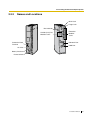
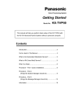
2.2.2
Names and Locations
MOH Jack
Pager Jack
Run Indicator
Outside (CO) Line
Modular Jacks
Protective Earth
Terminal
Extension
Modular
Jacks
RS-232C Port
USB Port
AC Inlet
Battery Interface
Power Switch
Installation Manual
25
2.2 Installing the Advanced Hybrid System
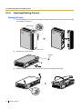
2.2.3
Opening/Closing Covers
Opening Covers
1. Pull the slide button to the right and, holding it, slide the cable cover upwards. Then turn the cable
cover slightly to remove it.
Slide Button
Cable Cover
2. Remove the 3 cover screws.
Screw
3. Holding the protrusions on both sides of the front cover, swing the cover open.
26
Installation Manual
2.2 Installing the Advanced Hybrid System
Removing/Attaching the Front Cover
If you prefer, you can remove the front cover.
Removing the Front Cover
Holding the front cover open at about a 45 angle, remove the front cover by pushing it in the
direction of the arrow as shown below.
45˚
Attaching the Front Cover
Fit the front cover to the main unit as shown below, and then close the front cover.
Closing the Covers
1. Close the front cover, then tighten the 3 cover screws.
Screw
Installation Manual
27
2.2 Installing the Advanced Hybrid System
2. Attach the rear hooks on the cable cover to the main unit, then swing the cable cover closed so
that the front hooks fit in place.
Cable Cover
Rear Hook
Front Hook
3. Slide the cable cover down until it locks.
Note
For safety reasons, keep the front cover closed while the PBX is in operation.
CAUTION
Tighten the above screws firmly to prevent the main unit from falling when the PBX is carried.
28
Installation Manual
2.2 Installing the Advanced Hybrid System
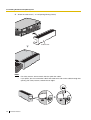
2.2.4
Securing the Cables
1. Attach the included strap to either of the 2 rails depending on your preference.
Rail
Rail
2. Bind the cables as shown.
Installation Manual
29
2.2 Installing the Advanced Hybrid System
3. Attach the cable cover. (o2.2.3 Opening/Closing Covers)
Cable Cover
Notes
•
•
30
Installation Manual
For safety reasons, do not stretch, bend, or pinch the cables.
If you prefer, you can cut the other side of the cable cover and run the cables through that
opening. For safety reasons, smooth the cut edges.
2.2 Installing the Advanced Hybrid System
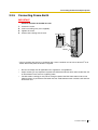
2.2.5
Connecting Frame Earth
IMPORTANT
Connect the frame of the PBX to earth.
1.
2.
3.
4.
Loosen the screw.
Insert an earthing wire (user-supplied)*.
Tighten the screw.
Connect the earthing wire to earth.
Earthing wire
To earth
Screw
* Use an earthing wire that has a conductor with a cross-sectional area of at least 0.75 mm2 or 18
AWG. Green-and-yellow insulation is required.
•
•
•
Be sure to comply with all applicable laws, regulations, and guidelines.
Proper earthing is very important to protect the PBX from external noise and to reduce the risk
of electrocution in the event of a lightning strike.
The AC cable's earthing pin may not be enough to protect the PBX from external noise and
lightning strikes. A permanent connection must be made between earth and the earth terminal
of the main unit.
Installation Manual
31
2.2 Installing the Advanced Hybrid System
2.2.6
Connecting Backup Batteries
Backup batteries and the Backup Battery Cable (KX-A227) provide a backup power supply to allow
full use of the PBX in the event of a power failure. In a power failure, the backup batteries
automatically maintain the power for the PBX without interruption.
1. Set the Power Switch of the PBX to the "OFF" position and disconnect the AC cord from the AC
outlet.
2. Connect the backup battery cable with 2 identical VRLA (Valve Regulated Lead Acid) batteries
(12 V DC × 2).
Connector
Fuse
Backup Battery Cable
Red
Black
Battery Interface
Backup Batteries (12 V DC x 2)
•
•
•
•
•
Turn on the power switch of the PBX only after the installation of the PBX is finished and AC cord
is plugged into the AC outlet.
For each backup battery, battery capacity of 14 Ah or below is recommended (otherwise, the
battery charge may not be maintained).
Make sure that the type and capacity of the 2 backup batteries are identical.
The backup battery cable should not be exposed to direct sunlight. Keep the backup battery
cable and the backup batteries away from heating appliances and fire. Place the backup batteries
in ventilated place.
For details about the backup batteries, refer to the manual intended for the batteries.
CAUTION
•
•
•
•
32
Installation Manual
Be sure to comply with all applicable laws, regulations, and guidelines.
Make sure that the polarities of the backup batteries and wiring are correct.
Make sure that you do not short the backup batteries or cables.
When replacing one of the batteries, use only the same or equivalent battery type
recommended by the battery manufacturer. There is a danger of explosion if the backup
batteries are incorrectly replaced.
Dispose of used batteries according to the manufacturer's instructions.
2.2 Installing the Advanced Hybrid System
•
The charging time of your battery varies depending on the charge remaining, the
characteristics of the battery charger, and the ambient temperature. Refer to the instructions provided by the battery manufacturer for details. The following is an example calculation of the time needed to charge a drained battery
(Battery rating: 7.2 Ah) connected to the PBX:
Charging Time (h) =
(h: hours)
Battery Rating 7.2 (Ah)
Initial Charging Current typ. 0.3 (A)
× 1-3
= 24-72 (h)
Installation Manual
33
2.2 Installing the Advanced Hybrid System
2.2.7
Wall Mounting
The PBX is designed for wall mounting only. The wall where the PBX is to be mounted must be able
to support the weight of the PBX. When wall mounting the main unit, use either the included screws,
or screws of the same size.
Mounting on a Wooden Wall
The included screws may be used when mounting the main unit on a wooden wall.
1. Place the template (found on the last page of this manual) on the wall to mark the 3 screw
positions.
120 mm
Template
232 mm
Note
When you print out the template, the distance on the paper output may deviate slightly from the
indicated measurement. In this case, use the indicated measurement.
2. Fit the washers on the screws, and drive the screws into the wall.
Washer
Drive the screw
to this point.
3. Affix the PBX to the screw heads.
34
Installation Manual
2.2 Installing the Advanced Hybrid System
Notes
•
•
•
Do not block the openings of the cabinet. Leave at least 20 cm of space above and 10 cm
to the sides of the PBX for ventilation.
Make sure that the wall behind the cabinet is flat and free of obstacles, so that the openings
on the back of the cabinet will not be blocked.
Be careful not to drop the cabinet.
Mounting on a Concrete or Mortar Wall
The included screws may be used when mounting the main unit on a concrete or mortar wall. Usersupplied anchor plugs are also necessary.
1. Place the template (found on the last page of this manual) on the wall to mark the 3 screw
positions.
120 mm
232 mm
Template
Note
When you print out the template, the distance on the paper output may deviate slightly from the
indicated measurement. In this case, use the indicated measurement.
2. Drill holes in the wall as marked and fit the anchor plugs (not included) into the holes.
Hammer
Anchor Plug
6.4 mm
29 mm
3. Fit the washers on the screws, and drive the screws into the anchor plugs.
Drive the screw
to this point.
Installation Manual
35
2.2 Installing the Advanced Hybrid System
4. Affix the PBX to the screw heads.
Notes
•
•
•
36
Installation Manual
Do not block the openings of the cabinet. Leave at least 20 cm of space above and 10 cm
to the sides of the PBX for ventilation.
Make sure that the wall behind the cabinet is flat and free of obstacles, so that the openings
on the back of the cabinet will not be blocked.
Be careful not to drop the cabinet.
2.2 Installing the Advanced Hybrid System
2.2.8
Installing Surge Protector
Overview
A massive electrical surge can be caused if lightning strikes a telephone cable 10 m above ground,
or if a telephone line comes into contact with a power line. A surge protector is a device that is
connected to an outside (CO) line to prevent potentially dangerous electrical surges from entering the
building via the outside (CO) lines and damaging the PBX and connected equipment.
To protect the PBX from electrical surges, we strongly recommend connecting the PBX to a surge
protector that meets the following specifications:
– Surge arrestor type: 3-electrode arrestor
– DC spark-over voltage: 230 V
– Maximum peak current: at least 10 kA
Additionally, proper earthing is very important for the protection of the PBX. (o 2.2.5 Connecting
Frame Earth)
Many countries/areas have regulations requiring surge protection. Be sure to comply with all
applicable laws, regulations, and guidelines.
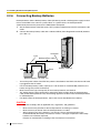
Installation
Outside
(CO) Line
Outside
(CO) Line
Outside
(CO) Line
Surge
Protector
Terminal
Board
Extn.
SLT
Earth
Extn.
PBX
Extn.
PT
Frame Earth
Extn.: Extension line
Installation Manual
37
2.2 Installing the Advanced Hybrid System
Outside Installation
(Main Building)
Outside
(CO) Line
Surge Protector
(Another Building)
Outside (CO) Line
SLT
Terminal
Board
Extn.
SLT
Extn.
PBX
PT
Surge
Protector
Extn.
Extn.
PT
Earth
Extn.: Extension Line
If you install an extension outside of the building, the following precautions are recommended:
a. Install the extension wire underground.
b. Use a conduit to protect the wire.
Note
The surge protector for an extension is different from that for an outside (CO) line.
Installation of an Earth Rod
Outside
(CO) Line
Surge
Protector
Earthing Wire
PBX
(Underground)
Earth Rod
1. Connect the earth rod to the surge protector using an earthing wire with a cross-sectional area
of at least 1.3 mm2.
38
Installation Manual
2.2 Installing the Advanced Hybrid System
2. Bury the earth rod near the protector. The earthing wire should be as short as possible.
3. The earthing wire should run straight to the earth rod. Do not run the wire around other objects.
4. Bury the earth rod at least 50 cm underground.
Notes
•
•
The above figures are recommendations only.
The length of the earth rod and the required depth depend on the composition of the soil.
Installation Manual
39
2.3 Installing Optional Service Cards
2.3
Installing Optional Service Cards
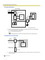
2.3.1
Location of Optional Service Cards
Optional service cards are installed by opening the cable and front covers of the main unit and affixing
the cards to the appropriate connectors. Each card should be installed in the appropriate location as
shown below.
See "System Components Table" for the description of each optional service card.
CAUTION
To protect the printed circuit boards (P-boards) from static electricity, do not touch parts on the
P-boards in the main unit and on the optional service cards. If you must touch the P-boards, wear
an earthing strap.
Connector
for KX-TE82460
Connector
for KX-TE82493
Connector for KX-TE82492 (KX-TEA308 only)
Notes
•
•
40
Installation Manual
Before installing optional service cards, turn off the PBX and unplug the AC cord.
Use extra care to make sure you do not damage the part of the case marked with a circle.
2.3 Installing Optional Service Cards
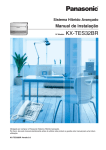
2.3.2
3-Port Caller ID Card (KX-TE82493)
Function
Adds Caller ID support for 3 outside (CO) lines. FSK and DTMF Caller ID types are supported. For information on the type of Caller ID used in your
area, contact your telephone company.
1. Loosen the screws and open the cable and front covers. (o 2.2.3 Opening/Closing Covers)
2. Slide the card between the guiderails until it clicks, and attach the connector to it.
KX-TE82493
3. Close the covers and secure the screws. (o 2.2.3 Opening/Closing Covers)
Note
To uninstall the card, follow the instructions illustrated below.
2
1
Guiderail
1. Push the catch on the side of one guiderail in the direction of the arrow to release it.
Installation Manual
41
2.3 Installing Optional Service Cards
2. Lift the edge of the card while holding the catch open. (Do not touch the circuit board of the card
during the operation.)
42
Installation Manual
2.3 Installing Optional Service Cards
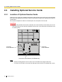
2.3.3
2-Port Doorphone Card (KX-TE82460)
Function
Supports the connection of 2 doorphones and 2 door openers.
1. Loosen the screws and open the cable and front covers. (o 2.2.3 Opening/Closing Covers)
2. Before installing the optional service card, cut and remove the dummy cover from the main unit.
Dummy Cover
3. Attach the 2-Port Doorphone Card to the main unit, connect the cord to the Doorphone Card
Connector and secure the screws.
Screw
Screw
Doorphone Connectors
Door Opener Terminal
KX-TE82460
Doorphone Card
Connector
4. Close the covers and secure the screws. (o 2.2.3 Opening/Closing Covers)
Installation Manual
43
2.3 Installing Optional Service Cards
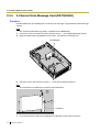
2.3.4
2-Channel Voice Message Card (KX-TE82492)
Function
Provides 60 minutes of recording time (2 channels) for messages using the Built-in Voice Message
Feature.
Note
The 2-Channel Voice Message Card is available for KX-TEA308 only.
1. Loosen the screws and open the cable and front covers. (o 2.2.3 Opening/Closing Covers)
2. Slide the card between the guiderails until it clicks, and attach the connector to it.
KX-TE82492
3. Close the covers and secure the screws. (o 2.2.3 Opening/Closing Covers)
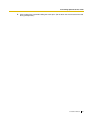
Note
To uninstall the card, follow the instructions illustrated below.
2
1
Guiderail
1. Push the catch on the side of one guiderail in the direction of the arrow to release it.
44
Installation Manual
2.3 Installing Optional Service Cards
2. Lift the edge of the card while holding the catch open. (Do not touch the circuit board of the card
during the operation.)
Installation Manual
45
2.4 Connecting Outside (CO) Lines
2.4
Connecting Outside (CO) Lines
2.4.1
Connecting Outside (CO) Lines
Connection
1. Insert the modular plugs of the telephone line cords (2-conductor wiring) into the outside (CO)
line jacks.
2. Connect the line cords to the terminal board or the modular jacks from the telephone company.
TEL Jack for Outside(CO)Line
R T
T: Tip
R: Ring
To Terminal Board or Modular Jacks
from the Telephone Company
46
Installation Manual
2.5 Connecting Extensions
2.5
Connecting Extensions
2.5.1
Connecting Extensions
Extension jacks can be used for proprietary telephones (PTs), Direct Station Selection (DSS)
Consoles, single line telephones (SLTs), and Voice Processing Systems.
Notes
•
Connect a display-equipped proprietary telephone (PT) to extension jack 01, as this
extension is automatically designated as the manager extension.
For KX-TEB308, 4 extension jacks out of 8 can be used for SLTs*1 only.
The following table shows the extension jack types.
•
Extension Jack Types
TEA308
TEB308
TEB308TW
Jack01-08
Jack01-04
Jack01-04
SLT only
—
Jack05-08
—
PT only
—
—
Jack05-08
Hybrid (PT/SLT)
Connection
Insert the modular plugs of the telephone line cords (2- or 4-conductor wiring) into the modular jacks
on the PBX.
TEL Jack for Extension
L R T H H: High
T: Tip
R: Ring
L: Low
To extensions
*1
Taiwan: PTs
Installation Manual
47
2.5 Connecting Extensions
Maximum Cabling Distance of Extension Wiring (Twisted Cable)
Cable
ø 0.4 mm:
ø 0.5 mm:
ø 0.6 mm:
CAT 5:
Max. Distance
140 m
229 m
360 m
229 m
Cable
ø 0.4 mm:
ø 0.5 mm:
ø 0.6 mm:
CAT 5:
Max. Distance
698 m
1128 m
1798 m
1128 m
PT and DSS
Console
SLT
2- or 4-conductor wiring is required for each extension as listed below. There are 4 pins that can be
used for connection: "T" (Tip), "R" (Ring), "H" (High) and "L" (Low).
Telephone
Wiring
SLT
1-pair wire (T, R)
PT (such as KX-T7735)
2-pair wire (T, R, H, L)
DSS Console
1-pair wire (H, L)
Note
If a telephone or answering machine with an A-A1 relay is connected to the PBX, set the A-A1
relay switch on the telephone or answering machine to the "OFF" position.
48
Installation Manual
2.5 Connecting Extensions
2.5.2
Connecting Extensions in Parallel
Any single line telephone (SLT) can be connected in parallel with a proprietary telephone (PT) to a
Hybrid Port as follows:
To a Hybrid Port
Modular
T-Adaptor
2-conductor wiring cord
Connect pins "T" and "R".
4-conductor wiring cord
Connect pins "T", "R", "H",
and "L".
PT
SLT
Note
An answering machine, fax machine or modem can be connected in parallel with a PT in the
same way as an SLT can.
Installation Manual
49
2.6 Connecting Doorphones and Door Openers
2.6
Connecting Doorphones and Door Openers
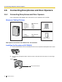
2.6.1
Connecting Doorphones and Door Openers
Up to 2 doorphones (KX-T30865) and 2 door openers (user-supplied) can be installed.
Maximum Cabling Distance
Cable
ø 0.4 mm:
ø 0.5 mm:
ø 0.6 mm:
CAT 5:
Max. Distance
70 m
110 m
150 m
110 m
Cable
ø 0.6 mm:
Max. Distance
150 m
Doorphone
Door Opener
Door opener current limit: 30 V DC/30 V AC, 3 A maximum
Installing the Doorphone (KX-T30865)
1. Loosen and remove the screw at the bottom of the case to separate the doorphone into 2 halves.
onic
as
Pan
Screw
2. Pass the wires through the hole in the base cover, and attach the base cover to a wall using 2
screws.
Screw
To the terminal box
50
Installation Manual
2.6 Connecting Doorphones and Door Openers
Note
Two kinds of screws are included with the KX-T30865. Please choose the appropriate screws for
your wall type.
: when a doorphone plate has been fixed to the wall
: when you wish to install the doorphone directly to the wall
3. Connect the wires to the screws located in the front cover.
To the terminal box
4. Re-attach the 2 halves and re-insert and tighten the screw.
Installation Manual
51
2.6 Connecting Doorphones and Door Openers
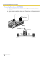
Connecting Doorphones (KX-T30865)
1. Connect the Doorphone Card to the terminal boxes using 4-conductor wiring and modular
connectors.
2. Connect the wires of doorphone 1 to the red and green screws on the appropriate terminal box.
3. Connect the wires of doorphone 2 to the yellow and black screws on the appropriate terminal
box.
View of Doorphone Connector Jack
Doorphone 2
Doorphone 1
4-conductor wiring
is required.
Terminal Box
Yellow
Red
Panasonic
Doorphone 1
52
Installation Manual
Black
Green
Panasonic
Doorphone 2
2.6 Connecting Doorphones and Door Openers
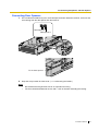
Connecting Door Openers
1. Use a flathead screwdriver to press and hold open the button below the terminal, and insert the
wire coming from the door opener into the terminal.
Door opener 2
Door opener 1
To the door openers
2. Wrap the strap around all of the cords. (o 2.2.4 Securing the Cables)
Notes
•
•
We recommend using UL1015 wire or an equivalent for wiring.
The wire should be between 0.45 mm and 1.1 mm in diameter excluding the coating.
Installation Manual
53
2.7 Connecting Doorbell or Door Chime
2.7
Connecting Doorbell or Door Chime
2.7.1
Connecting Doorbell or Door Chime
Use a flathead screwdriver to press and hold open the button below the terminal, and insert the wire
coming from the doorbell or door chime into the terminal. You can use a standard doorbell/door
chime. For more details, please consult your dealer. Refer to "2.6 Connecting Doorphones and Door Openers" for connecting doorphones (KX-T30865)
and door openers.
Door opener 2
Door opener 1
Relay 2 Relay 1
Doorbell/
Door Chime
54
Installation Manual
Door
Opener 1
2.8 Connecting Peripherals
2.8
Connecting Peripherals
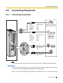
2.8.1
Connecting Peripherals
Cable
ø 0.4 mm:
ø 0.5 mm:
ø 0.6 mm:
CAT 5:
Max. Distance
10 m
10 m
10 m
10 m
Cable
ø 0.4 mm:
ø 0.5 mm:
ø 0.6 mm:
CAT 5:
Max. Distance
10 m
10 m
10 m
10 m
Paging system
(loudspeaker,
amplifier and
speaker, etc.)
Max. Distance
2m
PC
Max. Distance
5m
External audio source
(radio, CD player, etc.)
Printer
PC
Note
Be sure to comply with the above maximum distance between the PBX and each peripheral.
BGM/MOH
1 audio source (user-supplied), such as a radio or CD player, can be connected to the PBX and used
as the source of Background Music (BGM) and Music on Hold (MOH).
Connect a cable from the audio output (earphone jack, headphone jack, etc.) of the audio source to
Installation Manual
55
2.8 Connecting Peripherals
the MOH Jack of the PBX.
Use an EIAJ RC-6701 A plug (2-conductor, 3.5 mm in diameter).
•
Input impedance: 8 :
CAUTION
•
•
Notes
•
•
•
•
Do not force audio cables into the jacks. Doing so may damage the connections and cause
the audio to cut in and out.
The MOH port is an SELV port and should only be connected to an approved SELV device,
or in Australia, via the Line Isolation Unit with the Telecommunications Compliance Label.
Use the supplied audio source connector in the event that the user-supplied audio cable
connector is too long and does not fit when the front cover of the PBX is closed. Remove the
connector from the user-supplied audio cable, expose the bare cable, and attach the
supplied audio source connector.
When the PBX and external audio source are not connected to the same earth, a humming
noise may be heard in the BGM and MOH.
The audio source used for BGM and MOH is determined by system programming.
To adjust the sound level of the MOH, use the volume control on the external audio source.
Pager
Only 1 paging device (user-supplied) can be connected to the PBX.
Use an EIAJ RC-6701 A plug (2-conductor, 3.5 mm in diameter).
•
Output impedance: 600 :
CAUTION
The External Paging Jack is an SELV port and should only be connected to an approved SELV
device, or in Australia, via the Line Isolation Unit with the Telecommunications Compliance Label.
Notes
•
•
Use the supplied pager connector in the event that the user-supplied pager cable connector
is too long and does not fit when the front cover of the PBX is closed. Remove the connector
from the user-supplied pager cable, expose the bare cable, and attach the supplied pager
connector.
To adjust the sound level of the pager, use the volume control on the loudspeaker or
amplifier.
PC/Printer (via RS-232C)
A PC can be connected via the RS-232C interface and used to log and display call records, and
programme the PBX. A printer can also be connected, to print call records. Connect the PC or printer via an RS-232C cable (user-supplied).
Note
Use an RS-232C cross cable when connecting the PBX with a PC.
56
Installation Manual
2.8 Connecting Peripherals
Pin Assignments
Circuit Type
No.
1
5
6
9
Signal Name
Function
EIA
CCITT
2
RD (RXD)
Receive Data
BB
104
3
4
SD (TXD)
ER (DTR)
Transmit Data
Data Terminal Ready
BA
CD
103
108.2
5
6
SG
DR (DSR)
Signal Ground
Data Set Ready
AB
CC
102
107
7
8
RS (RTS)
CS (CTS)
Request To Send
Clear To Send
CA
CB
105
106
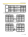
Connection Charts
For connecting a PC/printer with a 9-pin RS-232C connector
PBX
PC/Printer
Circuit Type
(EIA)
Signal
Name
Pin No.
Pin No.
Signal
Name
Circuit Type
(EIA)
BB
RD (RXD)
2
2
RD (RXD)
BB
BA
SD (TXD)
3
3
SD (TXD)
BA
CD
ER (DTR)
4
4
ER (DTR)
CD
AB
SG
5
5
SG
AB
CC
DR (DSR)
6
6
DR (DSR)
CC
CA
RS (RTS)
7
7
RS (RTS)
CA
CB
CS (CTS)
8
8
CS (CTS)
CB
For connecting a PC/printer with a 25-pin RS-232C connector
PBX
PC/Printer
Circuit Type
(EIA)
Signal
Name
Pin No.
Pin No.
Signal
Name
Circuit Type
(EIA)
BB
RD (RXD)
2
1
FG
AA
BA
SD (TXD)
3
3
RD (RXD)
BB
CD
ER (DTR)
4
2
SD (TXD)
BA
AB
SG
5
20
ER (DTR)
CD
CC
DR (DSR)
6
7
SG
AB
CA
RS (RTS)
7
5
CS (CTS)
CB
CB
CS (CTS)
8
6
DR (DSR)
CC
8
CD (DCD)
CF
Installation Manual
57
2.8 Connecting Peripherals
RS-232C Signals
•
Receive Data (RXD):…(input)
Carries signals from the printer or the PC to the PBX.
•
Transmit Data (TXD):…(output)
Carries signals from the PBX to the printer or the PC. Stays in "Mark" status unless data or
BREAK signals are being transmitted.
•
Data Terminal Ready (DTR):…(output)
This signal line is turned ON by the PBX to indicate that it is ON LINE. Circuit ER (DTR) ON
does not indicate that communication has been established with the printer or the PC. It is
switched OFF when the PBX is OFF LINE.
•
Signal Ground (SG)
Connects to the DC ground of the PBX for all interface signals.
•
Data Set Ready (DSR):…(input)
An ON condition of circuit DR (DSR) indicates that the printer or the PC is ready. Circuit DR
(DSR) ON does not indicate that communication has been established with the printer or the
PC.
•
Request To Send (RTS):…(output)
This is held ON whenever DR (DSR) is ON.
•
Clear To Send (CTS):…(input)
An ON condition of circuit CS (CTS) indicates that the printer or the PC is ready to receive
data from the PBX. The PBX does not attempt to transfer data or receive data when circuit
CS (CTS) is OFF.
•
Frame Ground (FG)
Connects to the unit frame and the earth ground conductor of the AC cord.
•
Data Carrier Detect (DCD):…(input)
An ON condition of circuit CD (DCD) indicates the data terminal (DTE) that the carrier signal
is being received by.
PC (via USB 1.1 interface)
A PC running the KX-TE308 Maintenance Console software can be connected via the USB interface
and used to programme the system and upload/download data to the PBX.
Pin Assignments
No.
58
2
1
3
4
Installation Manual
Signal Name
1
VBUS
2
USB D-
3
USB D+
4
GND
2.9 Power Failure Connections
2.9
Power Failure Connections
2.9.1
Power Failure Connections
When the power supply to the PBX fails, power failure transfer will switch from the current connection
to the Power Failure Connections.
Power Failure Connections connect a specific extension and an outside (CO) line in the event of
power failure as follows:
Outside (CO) line 1—extension (T, R) jack 01
Notes
•
•
•
•
In the event of a power failure, system memory is protected by a factory-provided lithium
battery. No system data will be lost, except for the Camp-on, Saved Number Redial, Last
Number Redial, and Call Park data.
The current connection automatically switches to the Power Failure Connection when the
power supply stops.
Proprietary telephones (PTs) cannot be used during a power failure. Therefore, we
recommend connecting a single line telephone (SLT) in parallel with a PT to extension jack
01.
As long as DC power is provided by the backup batteries, the PBX will remain fully
operational and the connection will not switch to the Power Failure Connections.
Installation Manual
59
2.10 Starting the Advanced Hybrid System
2.10 Starting the Advanced Hybrid System
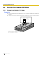
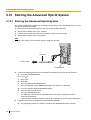
2.10.1 Starting the Advanced Hybrid System
This section explains the procedure for starting the PBX for the first time, with default values, or when
you wish to re-initialise the PBX.
1.
2.
3.
4.
Make sure that all outside (CO) lines you use are connected to the PBX.
Set the Power Switch to the "OFF" position.
Connect the AC cord to the PBX, then plug the AC cord into an AC outlet.
Set the Power Switch to the "ON" position.
Note
For safety reasons, do not stretch, bend, or pinch the AC cord.
AC Cord
To AC Outlet
Power Switch
5. Perform the following operation with a proprietary telephone (PT) connected to JACK 01.
a. Press the PROGRAM button.
b.
c.
d.
e.
f.
g.
h.
i.
Press
•
The PBX will be initialised with the default values. The type of outside (CO) lines is
automatically detected.
If the PBX does not function properly, refer to "4.1.5 System Reset with System Data Clear".
•
#.
Enter 1234.
Enter 999.
Press the NEXT (SP-PHONE) button.
Press the SELECT (AUTO ANS/MUTE) button until "All Para" is displayed.
Press the STORE (AUTO DIAL/STORE) button.
Press the END (HOLD) button.
Press the PROGRAM button.
6. Programme the PBX using either one of the following methods:
a. PC programming. Refer to "Section 3, Guide for KX-TE308 Maintenance Console".
60
Installation Manual
2.10 Starting the Advanced Hybrid System
b. PT programming. Refer to "3.3 PT Programming" of the Feature Guide. Users in countries
such as Italy and the Czech Republic are required to set the country code prior to all other
settings.
CAUTION
•
•
Notes
•
•
•
The PBX is powered as long as the AC cord is plugged into an AC outlet, even if the Power
Switch is set to the "OFF" position.
The power supply cord is used as the main disconnect device. Ensure that the AC outlet is
located/installed near the equipment and is easily accessible.
If the outside (CO) lines you use are not connected to the PBX, outside (CO) line type cannot
be automatically detected.
Use only the AC cord included with the PBX.
If the PBX will not be used for an extended period of time, set the Power Switch to the "OFF"
position and disconnect the AC cord from the AC outlet to conserve power.
Installation Manual
61
2.10 Starting the Advanced Hybrid System
62
Installation Manual
Section
3
Guide for KX-TE308 Maintenance Console
This section explains how to connect a PC to the Advanced
Hybrid system and get started using KX-TE308 Maintenance
Console.
Installation Manual
63
3.1 Installing KX-TE308 Maintenance Console
3.1
Installing KX-TE308 Maintenance Console
3.1.1
Installing KX-TE308 Maintenance Console on a PC
System Requirements
Operating System
•
Microsoft ® Windows ® 98 SE, Windows Me, Windows 2000, or Windows XP
Hardware
•
•
•
CPU: 300 MHz Intel ® Celeron ® or faster
RAM: At least 128 megabytes (MB) of available RAM
Hard disk space: At least 100 MB of space for the installation, and approximately 2 MB of
additional space for user files.
Setting the Password and Password Security
To maintain system security, a password is required to perform system programming. When KXTE308 Maintenance Console is started for the first time, the Quick Setup utility will ask you to set the
system password. To avoid unauthorised access and possible fraudulent dialling, do not disclose the
password.
Warning to the Installer regarding the system password
1. Please inform the customer of the importance of the password and the possible dangers if
it becomes known to others.
2. To avoid unauthorised access and possible fraudulent dialling, maintain the secrecy of the
password.
3. We strongly recommend that you change the default password value to something else for
reasons of system security. It is best to use a password of 7 digits.
4. Please change the password periodically.
5. If a system password is forgotten, it can be found by loading a backup of the system data
into a PC, and checking the password using the KX-TE308 Maintenance Console software.
If you do not have a backup of the system data, you must reset the PBX to its factory defaults
and reprogramme it. Therefore, we strongly recommend maintaining a backup of the system
data.
For more information on how to back up the system data, refer to the on-line help that
appears by selecting the Help menu during PC programming. However, as system
passwords can be extracted from backup copies of the system data file, do not allow
unauthorised access to these files.
Note
This PBX has only one system password. It can be changed by either PT programming or PC
programming. For this reason, the password can consist of numerals only.
64
Installation Manual
3.1 Installing KX-TE308 Maintenance Console
Installing KX-TE308 Maintenance Console
Notes
•
•
•
Before installing or uninstalling the software, be sure to close any open applications.
To install or uninstall the software on a PC running Windows 2000 Professional or Windows
XP Professional, you must be logged in as a user in the "Administrators" group.
The screenshots shown here are for reference only, and may differ from the screens
displayed on your PC.
1. Insert the included CD-ROM into the CD-ROM drive
of your PC.
The main screen will appear automatically.
2. Click Maintenance Console.
3. Double-click the setup file to run the installer. (Its
icon is shown here, on the left.)
4. Follow the on-screen instructions provided by the
installation wizard.
5. Select the appropriate model code. (The model
code is the suffix attached to the model number.)
The appropriate default data will be installed based
on the model code selected here.
6. Click Next.
7. Follow the instructions of the wizard.
Installation Manual
65
3.2 Connection
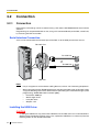
3.2
Connection
3.2.1
Connection
PBX features and settings can be customised using a PC and the KX-TE308 Maintenance Console
software. Programming can be performed both on-site, using a PC connected directly to the PBX, and off-site,
by accessing the PBX via modem.
Serial Interface Connection
A PC can be connected to the RS-232C port of the PBX, or to the USB port for faster access.
RS-232C Port
To COM Port
PC
To USB Port
PC
USB Port
Notes
•
•
For pin assignments and maximum cabling distance, refer to "2.8 Connecting Peripherals".
When connecting the KX-TE308 Maintenance Console to the PBX using an RS-232C cable,
assign the following values to the Serial Interface (RS-232C) port of the PBX through system
programming, "SMDR RS-232C Parameter [800]":
•
Baud Rate: 9600 bps
•
Word Length: 8 bits
•
Parity Bit: None
•
Stop Bit: 1 bit
Installing the USB Driver
CAUTION
Installing the USB driver may prevent the USB driver for KX-TDA series or PC Console/Phone
Software from functioning correctly. In this case, update the USB drivers as necessary from the
following folders on the included CD-ROM:
66
Installation Manual
3.2 Connection
KX-TDA Series: CD-ROM Drive:\TDA_USB Driver\TDA_USB Driver
PC Console/Phone Software: CD-ROM Drive:\TDA_USB Driver\T7601_USB Driver
Note
Before installing or uninstalling the driver, be sure to close any open applications.
Windows 98SE
1. Connect the PC to the PBX with a USB cable. The Add New Hardware Wizard will appear.
2.
3.
4.
5.
6.
7.
8.
Click Next.
Select Search for the best driver for your device. [Recommended], then click Next.
Select Specify a location, then click Browse.
Specify the folder containing the USB driver, CD-ROM Drive:\USB driver\Win98, then click OK.
Click Next.
Click Next.
Click Finish.
Note
If a dialog box appears asking you to restart your PC, restart the PC.
Windows Me
1. Connect the PC to the PBX with a USB cable. The Add New Hardware Wizard will appear.
2.
3.
4.
5.
6.
7.
8.
Select Specify the location of the driver [Advanced], then click Next.
Select Search for the best driver for your device. [Recommended].
Select Specify a location, then click Browse.
Specify the folder containing the USB driver, CD-ROM Drive:\USB driver\WinMe, then click OK.
Click Next.
Click Next.
Click Finish.
Note
If a dialog box appears asking you to restart your PC, restart the PC.
Windows 2000
1. Connect the PC to the PBX with a USB cable. The Found New Hardware Wizard will appear.
2.
3.
4.
5.
Click Next.
Select Search for a suitable driver for my device. [Recommended], then click Next.
Select Specify a location, then click Next.
Click Browse, and specify the folder containing the USB driver, CD-ROM Drive:\USB
driver\Win2000, then click Open.
6. Click OK.
7. Click Next.
8. Click Finish.
Installation Manual
67
3.2 Connection
Windows XP
1. Connect the PC to the PBX with a USB cable. The Found New Hardware Wizard will appear.
2.
3.
4.
5.
6.
7.
8.
68
Select Install from a list or specific location [Advanced], then click Next.
Select Search for the best driver in these locations.
Select Include this location in the search:, then click Browse.
Specify the folder containing the USB driver, CD-ROM Drive:\USB driver\WinXP, then click OK.
Click Next.
Click Continue Anyway.
Click Finish.
Installation Manual
3.2 Connection
3.2.2
Starting KX-TE308 Maintenance Console for the first time
When you start the KX-TE308 Maintenance Console with the Installer Level Programmer Code and
connect to the PBX for the first time after initialisation (with factory default setting), Quick Setup will
launch automatically. During Quick Setup, you will setup:
•
The country code of the PBX. (This setting is only available when the model code is set to
"CE" or "NE", and the country codes of the PBX and Maintenance Console do not match.)
•
The date and time. The PBX uses the date and time set to the PC.
•
The System Password.
•
The operator extension number.
•
Automatic Configuration for CO Line Type (DTMF/Pulse).
•
The feature numbers for Operator Call and Automatic Line Access.
•
Extension numbers and names.
•
The Numbering Plan type.
•
Ringing assignment for each outside (CO) line (either all extensions, or a specific extension).
Note
The screenshots shown here are for reference only, and may differ from the screens displayed
on your PC.
1. Start the KX-TE308 Maintenance Console software
from the start menu. (Start o Programs o KXTE308 Maintenance Console)
2. Type the Installer Level Programmer Code that was
set during the KX-TE308 Maintenance Console
installation.
3. a.
Click the check box to connect to the PBX.
Options will appear as shown here, on the left.
b. Type the System Password. (default: 1234)
c. Select the method of connection.
d. Click OK to log in.
4. Quick Setup starts. Follow the on-screen
instructions and assign the items as prompted.
Note
Software features, design, and system requirements are subject to change.
Installation Manual
69
3.2 Connection
3.2.3
Accessing PBX via Internal Modem
1. Start the KX-TE308 Maintenance Console software
from the start menu on your PC. (Start o Programs
o KX-TE308 Maintenance Console)
2. Type the Installer Level Programmer Code that was
set during the KX-TE308 Maintenance Console
installation.
3. Click the check box to connect to the PBX. Options
will appear as shown here, on the left.
4. Type the System Password. (default: 1234)
5. Select Modem, and click Setup.
When the mode of the PBX outside (CO) line that will be accessed is 'MODEM':
1.
2.
3.
4.
For Dial Number, enter the telephone number assigned to the internal modem of the PBX.
Select Auto (Tone) or Auto (Pulse) for Dial Type.
Click OK.
Click OK. The PC will connect to the PBX.
When the mode of the PBX outside (CO) line that will be accessed is 'DISA':
1. For Dial Number, enter the telephone number assigned to the internal modem of the PBX,
several pause symbols (',') and the Remote Maintenance Feature Number (for example:
01234567,,,,,729).
2. Select Auto (Tone) for Dial Type.
3. Click OK.
4. Click OK. The PC will connect to the PBX.
Notes
•
•
The number of pause symbols to be inserted differs depending on the PC modem used.
Auto (Pulse) Dial Type cannot be used.
When the mode of the PBX outside (CO) line that will be accessed is 'Normal':
1.
2.
3.
4.
5.
6.
70
Installation Manual
For Dial Number, enter the pause symbol (',').
Select Manual for Dial Type.
Click Initialise.
Click OK.
Click OK.
Dial the telephone number assigned to the outside (CO) line from a telephone connected in
parallel with the PC.
3.2 Connection
7. Ask the respondent to transfer the call to the internal modem of the PBX. ('Transfer' +
'Remote Maintenance Feature number')
8. Click OK and wait for 2 or 3 seconds, and then go on-hook before you hear a tone from the
modem. The PC will connect to the PBX.
Notes
•
•
•
•
•
The AT command 'Use V.22bis' may be required to configure the modem to communicate
with the PBX, depending on the modem (for example: "AT + MS = V22B").
The AT commands 'Use V.42' and 'Use V.42bis' may be required to configure the modem to
communicate with the PBX, depending on the modem.
The AT command to dial without waiting for a dial tone may be required to configure the
modem to communicate with the PBX, depending on the modem.
The AT command to set the Result Code format to text beginning with 'CONNECT' when a
connection is established may be required to configure the modem to communicate with the
PBX, depending on the modem.
If the Baud Rate (bps) is set too high or too low the modem may not be able to communicate
with the PBX, depending on the modem or PC. In this case, adjust the Baud Rate (bps) and
reconnect to the PBX.
Installation Manual
71
3.2 Connection
72
Installation Manual
Section
4
Troubleshooting
This section provides information on troubleshooting and
resetting the Advanced Hybrid System.
Installation Manual
73
4.1 Troubleshooting
4.1
Troubleshooting
4.1.1
Installation
PROBLEM
•
PROBABLE CAUSE
SOLUTION
Faulty connection
between the PBX and
telephone.
•
Plug the telephone into the same
extension port using a short telephone
cord.
If the telephone functions, then the
connection between the PBX and the
telephone must be repaired.
•
Faulty telephone.
•
Plug the telephone into a known
functioning extension port. If the telephone
does not function, replace the telephone.
•
A telephone with an A-A1 •
relay is connected.
Use a 2-wire cord.
Set the A-A1 relay switch of the telephone
to the "OUT" or "OFF" position.
•
Faulty extension card.
•
Exchange the card for a known functioning
one.
Extension telephone does •
not function.
•
Proprietary telephones
(PTs) connected to
extension jacks do not
operate, but single line
telephones (SLTs) do.
•
The H and L pins of
•
extension jacks may have
shorted.
Turn the Power Switch to the "OFF"
position. Fix the shorted part, then turn the
Power Switch to the "ON" position.
•
Noise heard through
external pager
(loudspeaker).
•
If using an amplifier, noise •
may be being introduced
through the cable
connecting the PBX and
the amplifier or
loudspeaker.
Use a shielded cable to connect the PBX
and the amplifier or loudspeaker. A shorter
cable will introduce less noise.
•
Audio (Music on Hold,
Background Music) is
distorted.
•
Audio level from the output •
of the audio source is too
high.
Decrease the output level of the external
audio source by using the volume control
on the audio source.
•
Speed Dialling or Onetouch Dialling does not
function.
•
Incorrect programming.
•
Store the outside (CO) line access number
(for example, 9 or 0, 81 through 83) at the
beginning of the telephone number.
•
Improper operation other
than the above.
•
Turn the Power Switch to the "OFF"
position, and then back to the "ON"
position.
74
Installation Manual
4.1 Troubleshooting
4.1.2
Connection
Telephone cord connecting the PBX and a proprietary telephone (PT):
Can you dial
an extension?
No
CAUSE
SOLUTION
The T/R pins are connected to the H/L
pins.
H
T
R
L
H
T
R
L
Use the correct cord (the
inner 2 wires are for T/R and
the outer 2 wires are for H/L).
Extension
PBX
Telephone cord connecting the PBX and a single line telephone (SLT):
CAUSE
SOLUTION
The T/R pins are connected to the H/L
pins.
H
T
R
L
T
R
PBX
Yes
Use the correct cord (the
inner 2 wires are for T/R).
Extension
Telephone cord connecting the PBX and an SLT that is polarity-sensitive:
CAUSE
SOLUTION
The T and R pins are crossed over.
H
T
R
L
Reverse the connections of
the T/R pins.
T
R
PBX
Extension
Telephone cord connecting an outside (CO) line and the PBX:
CAUSE
SOLUTION
The outside (CO) line(s) is
connected to the H/L pins.
Can you dial
out using an
outside (CO)
line?
Reconnect the outside
(CO) line(s) to the T/R pins
of the telephone jack using
2-conductor wiring.
No
T
R
Outside (CO) line
PBX
Installation Manual
75
4.1 Troubleshooting
4.1.3
Operation
PROBLEM
PROBABLE CAUSE
•
When using the
speakerphone on an
analogue proprietary
telephone, no sound is
heard.
•
•
The proprietary telephone •
(PT) does not ring.
•
During a power failure,
PTs connected to jack
number 01 does not
operate.
•
Outside (CO) line calls
•
cannot be made with a PT.
•
An SLT set to "tone"
dialling mode cannot
make calls.
The HANDSET/
HEADSET selector is set
to the "HEADSET"
position.
SOLUTION
•
The ringer volume is set to •
off.
•
•
A flexible button on the PT •
has not been programmed
to select an outside (CO)
line.
There may be something
wrong with the DTMF
receiver.
When the headset is not used, set the
HANDSET/HEADSET selector to the
"HANDSET" position.
Set to "HIGH" or "LOW".
Only single line telephones (SLTs) can be
used during a power failure. Disconnect
the PT and connect an SLT.
Programme the CO buttons. Refer to
"1.18.2 Flexible Buttons" in the Feature
Guide.
1. Select "Enable" for DTMF receiver 1 and
"Disable" for DTMF receiver 2 through
system programming, "DTMF Receiver
Check [107]".
2. Try to make a call using a tone-type SLT
connected to one of extension jacks 01–
08.
3. If you cannot make the call, the problem
may have been caused by DTMF receiver
1. If the call can be made, go to step 4.
4. Try DTMF receiver 2. Select "Disable" for
DTMF receiver 1 and "Enable" for DTMF
receiver 2 through system programming,
"DTMF Receiver Check [107]", and make
another call. If you cannot make the call,
the problem may have been caused by
DTMF receiver 2. If the call can be made,
go to step 5.
5. Check the other 4 DTMF receivers the
same way through "DTMF Receiver Check
[107]" in system programming.
76
Installation Manual
4.1 Troubleshooting
4.1.4
System Restart
If the PBX does not operate correctly, confirm that the operation/feature is being used correctly and
refer to the Troubleshooting section if necessary. If the PBX still does not operate correctly, restart the
PBX.
When the PBX is restarted:
•
Calls on Hold are terminated.
•
Calls on Exclusive Hold are terminated.
•
Calls in progress are terminated.
•
Automatic Callback Busy (Camp-on) is cleared.
•
Call Park is cleared.
•
Last Number Redial is cleared.
•
Saved Number Redial is cleared.
No other data is cleared by System Restart.
1. To restart the PBX, turn the Power Switch to the "OFF" position, then turn the Power Switch back
to the "ON" position.
Note
If the PBX still does not operate correctly, please see "4.1.5 System Reset with System Data
Clear".
Installation Manual
77
4.1 Troubleshooting
4.1.5
System Reset with System Data Clear
When the PBX does not operate correctly after restarting, you can clear the programming data stored
in the PBX. The PBX will restart with the default settings.
1. Make sure that all outside (CO) lines you use are connected to the PBX.
2. Slide the System Clear Switch to the "CLR" position.
3. Press the Reset Button, and then return System Clear Switch to the "NOR" position before the
power indicator stops flashing. (The power indicator will flash for about 5 seconds.)
CAUTION
Before touching the System Clear Switch and Reset Button, put on an earthing strap.
Notes
•
•
After pressing the Reset Button, make sure to return the System Clear Switch to the "NOR"
position before the power indicator stops flashing, otherwise the system data will not be
cleared.
The recorded OGMs for DISA, UCD, and Built-in Voice Message are not cleared by the
System Data Clear.
Reset Button
RESET
NOR/CLR
System Clear Switch
78
Installation Manual
Index
Installation Manual
79
Index
Numerics
P
2-Channel Voice Message Card (KX-TE82492)
2-Port Doorphone Card (KX-TE82460)
43
3-Port Caller ID Card (KX-TE82493)
41
44
Power Failure Connections
R
Removing/Attaching the Front Cover
A
About the Installation Manual
7
About the Other Manuals
7
Accessing PBX via Internal Modem
Basic System Construction
Before Installing
22
Safety Installation Instructions
22
Securing the Cables
29
Serial Interface Connection
66
Setting the Password and Password Security
64
Specifications
17
Starting KX-TE308 Maintenance Console for the first time
Starting the Advanced Hybrid System
60
System Capacity
19
System Components Table
2
System Connection Diagram
16
System Data
19
System Highlights
14
System Outline
13
System Requirements
64
System Reset with System Data Clear
78
System Restart
77
70
15
C
Characteristics
18
Connecting Backup Batteries
32
Connecting Doorbell or Door Chime
54
Connecting Doorphones and Door Openers
Connecting Extensions
47
Connecting Extensions in Parallel
49
Connecting Frame Earth
31
Connecting Outside (CO) Lines
46
Connecting Peripherals
55
Connection
66, 75
50
T
Troubleshooting
G
General Description
17
Guide for KX-TE308 Maintenance Console
73
U
63
Unpacking
24
I
W
Installation
21, 74
Installation Precautions
22
Installing KX-TE308 Maintenance Console
65
Installing KX-TE308 Maintenance Console on a PC
Installing Optional Service Cards
40
Installing Surge Protector
37
Installing the Advanced Hybrid System
24
Installing the USB Driver
66
Wall Mounting
34
Wiring Precautions
22
64
L
Location of Optional Service Cards
40
M
Main Unit
15
Maximum Cabling Distance of Extension Wiring (Twisted Cable)
Maximum Cards and Terminal Equipment
19
Mounting on a Concrete or Mortar Wall
35
Mounting on a Wooden Wall
34
N
Names and Locations
25
O
Opening/Closing Covers
Operation
76
Installation Manual
26
27
S
B
80
59
48
69
120 mm
Install a screw here.
Install a screw here.
TEMPLATE FOR WALL MOUNTING
1. Copy or print this template and place it on the wall.
2. Install the screws as marked.
If you mount the main unit on a concrete or mortar wall,
fit anchor plugs (not included) into the wall beforehand.
3. Hook the unit onto the screw heads.
Install a screw here.
60 mm
232 mm
Note
Make sure to set the print size to correspond with the size
of this page. If the dimensions of the paper output still
deviate slightly from the measurements indicated here,
use the measurements indicated here.
Panasonic Communications Co., Ltd.
1-62, 4-chome, Minoshima, Hakata-ku, Fukuoka 812-8531, Japan
Copyright:
This material is copyrighted by Panasonic Communications Co., Ltd., and may be reproduced for internal
use only. All other reproduction, in whole or in part, is prohibited without the written consent of Panasonic
Communications Co., Ltd.
© 2005 Panasonic Communications Co., Ltd. All Rights Reserved.
PSQX3525ZA KK0405HS0