1
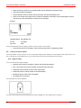
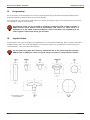
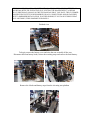
TRAC ABOUT, INC.
IRV2000
OWNERS MANUAL
Trac About, Inc.
Newton, Kansas
316-283-5660
An open letter to the owner of
THE TRAC ABOUT
MODEL IRV2000
PLEASE READ THE OPERATOR S PART OF THIS MANUAL
BEFORE OPERATING THE IRV2000
Thank you for choosing the Trac About IRV2000. We sincerely hope it
will allow you much more freedom to go where you would like to go. The
IRV2000 was made for safety and ease of going where you would like to go. It
operates quite well inside a home, school, shopping mall, church or any building
that will accept motorized chairs. It’s construction and low center of gravity make
the machine extremely safe.
Outdoors the IRV2000 is unsurpassed for its ability to take you over rough
terrain, through mud, snow, and seaside sand. It can cross curbs and other
obstructions up to 4-5 inches if you cross them at a slight angle. THE IRV2000
WILL NOT GO UP A STAIRWAY.
To get the most enjoyment and use of your IRV2000, you really should
read the manual before operating. We have tried to make it brief and to the point.
We hope you enjoy.
If for any reason you have a problem with the IRV2000, please call Trac
About Inc. at 1-800-458-8616 or e-mail from the web site, www.tracabout.com.
Sincerely at your service,
The gang at Trac About Inc.
TRAC ABOUT, INC.
1801 SE 9th ST., PO BOX 502, NEWTON, KS.67114-0502
316-283-5660*800-458-8616*FAX316-283-0693
www.tracabout.com
A PERSONAL AGREEMENT
BETWEEN THE OWNER AND TRAC ABOUT INC.
I do hereby agree that this IRV2000 (serial number_________________) has been
demonstrated to the best of my understanding. I will ask an authorized
representative of TRAC ABOUT INC. if I should have any questions in the future
about operation or maintenance. I will first go the Web page of
www.tracabout.com to find my answer by directly reading or by E-mail. I will call
1-800-458-8616 if I don’t have access to the INTERNET or if I need more help.
I understand this IRV2000 has been setup for me and only me. Any other person
that operates it will do so at their own risk. TRAC ABOUT INC. nor any person
associated will not be held accountable for any damage or injury done by the
operation of this machine.
Signed _______________________________ Date________________
(check one or both)
Owner
Operator
I agree to allow TRAC ABOUT, INC. to use my name, comments and or photos
for promotional uses in demonstrating the abilities of the IRV 2000. I understand
that there will be no monetary gain now or in the future from TRAC ABOUT’S
use of my name, comments and or photos.
I give permission __________
(Initial)
word/tracbout/manual\ownagre.doc
I do not give my permission _________
(Initial)
Table of Contents
Trac About IRV2000
BY TOPIC
Battery charge Indicator lights................ Page 3,5
Battery charging...................................... Page 6
Battery replacement................................ Page 6
Bearing replacement............................... Page 12
Changing the Batteries.............................Page 6
Charging the battery.................................Page 6
Cleaning and Washing.............................Page 13
Drive pin replacement..............................Page 9
Lights flashing...................................... Page 10
INSTRUCTIONS OF OPERATION.......Page 2,4
Introduction to the IRV2000....................Page 1
Jack operation......................................... Page 7, 7a
Joystick panel explanation.......................Page 2,4
Lights flashing, what do they mean...........Page 10
Locking the Joystick (80 amp Controller).
Page 2
Safety Tips............................................. Page 1
Speed selection....................................... Page 2,4
Stalling or Power out problem..................Page 11
Track adjustment.......................................Page 7, 7a
Track and Wheel positions........................Page 3,5,8
Track replacement.....................................Page 7, 7a
Trouble shooting section…......................Page 10,11
Unlocking the drive pins….......................Page 9
Unlocking the Joystick (80 amp Controller)
Page 2
Table of Contents
Trac About IRV2000
BY PAGE NUMBER
Safety Tips............................................. Page
Introduction to the IRV2000....................Page
Speed selection....................................... Page
Unlocking the Joystick (80 amp Controller). Page
Locking the Joystick (80 amp Controller).
Page
Joystick panel explanation.......................Page
INSTRUCTIONS OF OPERATION.......Page
Battery charge Indicator lights..................Page
Track and Wheel positions........................Page
Battery charging......................................Page
Charging the battery.................................Page
Changing the Batteries.............................Page
Battery replacement.................................Page
Jack operation......................................... Page
Track adjustment.......................................Page
Unlocking the drive pins..........................Page
Stalling or Power out problem..................Page
Lights flashing..................................
Page
Trouble shooting section.........................Page
Lights flashing, what do they mean...........Page
Track replacement.....................................Page
Bearing replacement…..............................Page
Drive pin replacement…...........................Page
Cleaning and Washing…..........................Page
Warranty…............................Appendices
Radio and Interference….......Appendices
Parts list and parts location ..Appendices
Circuit Breaker (if equipped)…. Appendices
Inserted pages for Penny Giles 120 Amp
Controller
(No page numbers)
1
1
2,4
2
2
2,4
2,4
3,5
3,5,8
6
6
6
6
7, 7a
7, 7a
9
11
10
10,11
10
7, 7a
12
9
13
Battery Replacement for Elevating Seating System
(if equipped)................................................................. Appendices
03-29-02 revised 9-13-06, 10-19-09
OWNERS MANUAL
THE TRAC ABOUT
MODEL IRV2000
YOU MUST READ THIS MANUAL BEFORE FIRST OPERATING THE IRV2000.
Thank you for purchasing the TRAC ABOUT IRV2000. Please read at least the
first 3 pages before operating the machine.
We would like to hear from you with any comments or suggestions about the IRV2000.
Please call 1-800-458-8616. Any changes or new information can be found on our web
site at www.tracabout.com.
OPERATION SAFETY
The IRV2000 has been built and tested to allow you more freedom and safety then most
other vehicles on the market. The safety suggestions listed below, are to help you enjoy
as much pleasure as possible.
Always wear your seat belt. The IRV2000 is designed for your safety and
pleasure out of doors. Sometimes the going could get a little rough.
If the battery lights show two red and one amber, you need to return and charge the
batteries. Do not charge the batteries if the battery charger is wet.
Do not drive the IRV2000 in vehicle areas. It is not a legal street vehicle.
It is not recommended to drive parallel on an incline greater than 15 degrees.
Do not drive up a slop of more than 20 degrees. BACK THE MACHINE UP A
STEEP GRADE, going forward may cause it to go over backwards.
Do not ride the IRV2000 on a ramp that is not rated for at least 1000 pounds.
Do not unlatch the drive pins and let it coast down hill. You will not have control.
Do not drive in water deeper than the top of the track.
If you drive the IRV2000 on an ocean beach, wash off all salt each day.
Do not high pressure wash under the seat mount. (This is where all the electronics
for the IRV2000 resides. After washing let the machine set until all water is gone.
Do not operate the IRV2000 if the controls are wet.)
Lock the Joystick controller when leaving the IRV2000 unattended.
WARNING: Allow only one person at a time on the IRV2000. Violation of the machine
could result in personal injury or property damage.
Page 1
12-05-00
INSTRUCTIONS TO OPERATE THE IRV2000
The Instructions of Operation are intended for you to have the most fun and the least
amount of frustrations while you operate the IRV2000. Please read the first 3 pages AND
page 11 of this manual before attempting to operate your new machine.
Keep in mind that the IRV2000 weights about 400 pounds without an operator. It can
cause damage to persons and property if not operated properly.
You can mount the IRV2000 from either side of the seat simply by raising the arm of the
seat. Sit down, spin in the seat and lower the arm rest. FASTEN YOUR SEAT BELT.
YOU ARE READY TO GO WHERE YOU WOULD LIKE TO GO!! The following
topics will explain the operation of each element of the Joystick controller.
GETTING STARTED USING THE 80 AMP
CONTROLLER
(If you have the100 amp controller, please see pages 4,5)
Battery Charger
Plug-in
Battery Lights
System
The following is an explanation of the Joystick
Status
Off-On
LED
control.
Speed
Key Location
1/0
Press the long I|O button. If the Joystick will not
Selector
Horn
work, you will see a little red light flashing on the
Key Location. Touch the magnetic key on the Key
Speed Indicator
Location red light. This will allow the Joystick to
activate. (If you want to re-lock the Joystick, have
power on and touch the magnetic key on the Key
Joy Stick
Location red light.)
You will also see the Battery Lights come on. If
Power Plug-in
the battery is fully charged, you will see two red
lights, two yellow lights and two green lights. You
will see in the Speed Indicator window the speed number or actuator letter. “A” or “b”
SELECTING SPEEDS
Speed
Selector
Press the Speed Selector until you see a “1” appear in the Speed
Indicator window. If you press the Speed Selector again, you will
see a “2” appear in the window.
The Joystick has a total of five speeds. The higher the number the faster the IRV 2000
will go. To change to a lower speed you must continue to press the button through the
speeds and letters to obtain the desired speed. You will see a letter appear after speed “5”.
Refer to the section WHEEL POSITIONS for an explanation.
( NOTE: beginning
operation in speed is advisable “1” or “2” until you are familiar with the operation of the
Joystick.)
Speeds are the result of power levels. If you need more power you need to select a higher
speed setting and then adjust the ground speed by moving the lever slightly.
Page 2 03-29-02
DRIVING THE IRV 2000 WITH THE JOYSTICK
Moving the Joystick forward will drive the IRV 2000 forward. If you push the stick just a
little, you will go slow. If you push it a lot, you will go as fast as the Speed Indicator is
set. If you move the stick a little to the left or right, you will turn in that direction in a
large circle. If you move it a lot, you will turn very short. If you pull back on the stick,
you will go backwards. If you release the Joystick you will stop abruptly. Try to move
the Joystick very smoothly to avoid sudden jerks.
WHEEL POSITIONS
SEE PAGE 8 FOR DIAGRAM
If you continue to press the Speed Selector again and again, you will see an “A” or a “b”
in the Speed Indicator window. These letters are used to raise and lower the tail wheel
“A” or the large center wheels “b”. Move the lever sideways to change the letter. Now if
you push forward or pull back on the Joystick, the wheel will go down or up. Try to
cross obstacles at an angle. You can cross a 5" curb safely if you cross at an angle.
Cross small logs and ditches the same way.
NOTE: If you run the center wheels all the way down and the caster all the way down,
you now have a three-point setup that allows tight turns on hard surfaces as well as on
carpet and throw rugs.
BATTERY LIGHTS
The Joystick controller has six battery lights. They will show how much charge is left in
the batteries. When the batteries are fully charged, all six lights will light. As the batteries
loose their charge, the green light will be the first to quit. If both of the green and yellow
lights go out, you have approximately 15 minutes before the machine quits. You can run
the batteries down to the point that the left (red) light will begin to
Battery Lights
flash. When that happens, you do not have much time left. The
battery charge life will depend on the load and the terrain. You
should never leave the battery with a low charge. It will damage the
batteries over time.
If the IRV2000 has a problem, normally the little red light on the I\O begins to flash.
Turn to the section titled, TROUBLE SHOOTING and follow the instructions.
NOTE: IF THE IRV2000 IS LEFT OUTDOORS OR IF YOU WANT HIGH
SECURITY, UNPLUG THE JOYSTICK AND REMOVE IT FROM THE ARMREST.
Page 3
03-29-02
GETTING STARTED USING THE 100 AMP CONTROLLER
(If you have the 80 amp controller, please see pages 2,3)
The following is an explanation of the Joystick
control. Press the round OFF/ON Button. If
the Joystick will not work, you will see the
Battery Lights flashing. Refer to the flash code
section.
Otherwise, you should see the Battery Lights
and the Speed Indicator Lights come on
without flashing. If the battery is fully charged,
you will see three red lights, four yellow lights
and three green lights. Also notice the Speed
Indicator Lights (1-5), indicating what speed
range the unit is in, one light being the slowest
speed available.
Battery Charger
Plug-in Location
Speed/Mode
Selector
MODE
Wheel Location
Lights
Off/On
Battery
Lights
Horn
Button
Speed Indicator
Lights
JoyStick
Lever
SELECTING SPEEDS
Press the Speed/Mode Selector button. You should see the
Speed Indicator Lights flash. Move the Joystick Lever to the
right to increase speed, and to the left to decrease speed. To
operate in that speed, simply move the Lever forward or back. You can also
change speed while moving by pressing the Speed/Mode Selector button. The
Joystick has a total of five speeds.
( NOTE: beginning operation in speed “1” or “2” lights is advisable until you are
familiar with the operation of the Joystick.)
DRIVING THE IRV 2000 WITH THE JOYSTICK
Moving the Joystick forward will drive the IRV 2000 forward. If you push the
stick just a little, you will go slow. If you push it a lot, you will go as fast as the
Speed Indicator is set. If you move the stick a little to the left or right, you will
turn in that direction in a large circle. If you move it a lot, you will turn very short.
If you pull back on the stick, you will go backwards. If you release the Joystick
you will stop abruptly.
Try to move the Joystick very smoothly to avoid sudden jerks.
Page 4
03-29-02
WHEEL POSITIONS
SEE PAGE 8 FOR DIAGRAM
If you press the Speed/Mode Selector twice, you will see one of the
two red Wheel Location Lights come on in the wheelchair picture. This
mode is used to raise and lower either the tail wheel or the large center
wheels, depending on which red light is lit. The light in the “seat
bottom” is for the center wheels. The light in the “seat back” is for the tail wheel.
Move the lever sideways to change the location. Now if you push forward or pull
back on the Joystick, the wheels will go down or up. Try to cross obstacles at an
angle. You can cross a 5" curb safely if you cross at an angle. Cross small logs
and ditches the same way.
NOTE: If you run the center wheels all the way down and the tail wheel all the way
down, you now have a three-point setup that allows tight turns on hard surfaces as
well as on carpet and throw rugs.
BATTERY LIGHTS
The Joystick controller has ten Battery Lights. They will show how much charge
is left in the batteries. When the batteries are fully charged, all ten lights will light.
As the batteries loose their charge, the green lights will be the first to quit. If all of
the green and yellow lights go out, you have approximately 15
minutes before the machine quits. You can run the batteries down
to the point that the last red light will begin to flash. When that
happens, you do not have much time left. The battery charge life
will depend on the load and the terrain. You should never leave the
battery with a low charge. It will damage the batteries over time.
If the IRV2000 has a problem, normally the Battery Lights begin to flash. Turn to
the section titled, TROUBLE SHOOTING and follow the instructions.
NOTE: IF THE IRV2000 IS LEFT OUTDOORS OR IF YOU WANT HIGH
SECURITY, UNPLUG THE JOYSTICK AND REMOVE IT FROM THE
ARMREST.
Page 5
03-29-02
PG DRIVES TECHNOLOGY
1
R-NET TECHNICAL MANUAL- OPERATION
Introduction
The relevant contents of this chapter should be included in the wheelchair’s operating guide. Further copies are available from
PGDT in either written or disk (Adobe PDF) format. Copies should not be made without the express permission of PG Drives
Technology.
The operation of the R-net varies dependent on programming. This chapter covers all types of operation. It is the responsibility of
the wheelchair manufacturer to ensure that only the relevant sections of this chapter are included in the wheelchair’s operating
manual.
The operation of the R-net wheelchair control system is simple and easy to understand. The control system incorporates state-ofthe-art electronics, the result of many years of research, to provide you with ease of use and a very high level of safety. In
common with other electronic equipment, correct handling and operation of the unit will ensure maximum reliability.
Please read this chapter carefully - it will help you to keep your wheelchair reliable and safe.
2
General
An R-net control system comprises a minimum of two modules - Joystick Module and Power Module. Because of the modular
design, the depth of the control system can be greatly increased. The following diagram shows the basic set-up.
2.1
Handling
Avoid knocking your control system and especially the joystick. Be careful not to strike obstacles with the control system or joystick
when you drive. Never drop the control system.
When transporting your wheelchair, make sure that the control system is well protected. Avoid damage to cables.
2.2
Operating Conditions
Your control system uses industrial-grade components throughout, ensuring reliable operation in a wide range of conditions.
However, you will improve the reliability of the control system if you keep exposure to extreme conditions to a minimum.
XXXXXX
SK77981/4
XX
13
R-NET TECHNICAL MANUAL- OPERATION
PG DRIVES TECHNOLOGY
Do not expose your control system or its components to damp for prolonged periods. If the control system becomes
contaminated with food or drink clean it off as soon as possible.
2.3
Cleaning
Clean the control system and the joystick with a cloth dampened with diluted detergent. Be careful when cleaning the joystick
and screen.
Never use abrasive or spirit-based cleaners.
3
Mating Connectors
To connect the Communication Cables:
•
Holding the connector housing, firmly push the connector into its mate until you can no longer see the yellow
plastic.
The connectors are secured using a friction system.
To disconnect the Communication Cables:
•
Holding the connector housing firmly, pull the connectors apart.
Do not hold or pull on the cable. Always grip the connector when connecting and disconnecting.
When the control system is first switched on after a connection, or system component change the
Timer will be displayed whilst the system checks itself and then the Re-start icon will be
displayed. Switch the control system off and on again to operate.
XX
14
XXXXXXX
SK77981/4
PG DRIVES TECHNOLOGY
4
R-NET TECHNICAL MANUAL- OPERATION
Controls
The R-net control system has two versions of Joystick Module – with and without lighting control. Most of the controls are common
to both however, the lighting buttons are only included on Joystick Module with lighting control. Each of the controls is explained
within this section.
XXXXXXX
SK77981/4
XX
15
R-NET TECHNICAL MANUAL- OPERATION
4.1
PG DRIVES TECHNOLOGY
Joystick
The primary function of the joystick is to control the speed and direction of the wheelchair. The further you push the joystick from
the center position the faster the wheelchair will move. When you release the joystick the brakes are automatically applied.
If the wheelchair is fitted with actuators, the joystick can also be used to move and select actuators, refer to section 3.8 for more
details.
4.2
Buttons
4.2.1
On/off Button
The on/off button applies power to the control system electronics, which in turn supply power to the wheelchair’s motors. Do not
use the on/off button to stop the wheelchair unless there is an emergency. (If you do, you may shorten the life of the wheelchair
drive components).
4.2.1
Horn Button
The Horn will sound while this button is depressed.
4.2.2 Speed Decrease Button
This button decreases the maximum speed setting.
Depending on the way the control system has been programmed a momentary screen may be displayed when the button is
pressed.
Refer to section 5 for details of the momentary screen
Refer to Chapter 3 - Programming for details.
XX
16
XXXXXXX
SK77981/4
PG DRIVES TECHNOLOGY
R-NET TECHNICAL MANUAL- OPERATION
4.2.3 Speed Increase Button
This button increases the maximum speed setting.
Depending on the way the control system has been programmed a momentary screen may be displayed when the button is
pressed.
Refer to section 5 for details of the momentary screen
Refer to Chapter 3 - Programming for details.
4.2.4 Mode Button
The Mode button allows the user to navigate through the available operating Modes for the control system. The available modes
are dependant on programming and the range of auxiliary output devices connected to the control system.
Refer to Chapter 3 - Programming for details.
4.2.5 Profile Button
The Profile button allows the user to navigate through the available Profiles for the control system. The number of available Profiles
is dependant on how the control system is programmed.
Depending on the way the control system has been programmed a momentary screen may be displayed when the button is
pressed.
Refer to section 5 for details of the momentary screen
Refer to Chapter 3 - Programming for details.
4.2.6 Hazard Warning Button and LED
This button activates and de-activates the wheelchairs hazard lights. Depress the button to turn the hazards on and depress the
button again to turn them off.
When activated the hazard LED and the indicator LED’s will flash in sync with the wheelchair’s indicators.
4.2.7 Lights Button and LED
This button activates and de-activates the wheelchairs lights. Depress the button to turn the lights on and depress the button
again to turn them off.
When activated the lights LED will illuminate.
4.2.8 Left Indicator Button and LED
This button activates and de-activates the wheelchair’s left indicator. Depress the button to turn the indicator on and depress the
button again to turn it off.
When activated the left indicator LED will flash in sync with the wheelchair’s indicator.
4.2.9 Right Indicator Button and LED
This button activates and de-activates the wheelchair’s right indicator. Depress the button to turn the indicator on and depress
the button again to turn it off.
When activated the right indicator LED will flash in sync with the wheelchair’s indicator.
4.2.10 External On/off Switch Jack
This allows the user to turn the control system on and off using an external device, such as a buddy button.
XXXXXXX
SK77981/4
XX
17
R-NET TECHNICAL MANUAL- OPERATION
PG DRIVES TECHNOLOGY
4.2.11 External Profile Switch Jack
This allows the user to select Profiles using an external device, such as a buddy button.
To change the Profile whilst driving simply press the button.
If the control system is set to latched drive or actuator control operation, then the polarity of the jack input is reversed to effect a
fail safe system; meaning this input will provide an External Profile Switch function and an Emergency Stop Switch function.
The Joystick Module is supplied with rubber bungs that must be inserted into the Jack Socket
when no external device is connected.
4.3
LCD Screen
The status of the control system can be understood by observing the LCD screen. The control system is on when the screen is
backlit.
Refer to section 5 for details on screen symbols.
4.5
Charger Socket
This socket should only be used for charging or locking the wheelchair. Do not connect any type of programming cable into this
socket.
Refer to section 10 for more details on charging.
This socket should not be used as a power supply for any other electrical device. Connection of other electrical devices may
damage the control system or affect the E.M.C. performance of the wheelchair.
The control system’s warranty will be voided if any device other than a battery charger supplied,
with the wheelchair, or the lock key is connected into this socket.
5
LCD Screen - Monochrome
The status of the control system can be understood by observing the LCD screen.
5.1
Screen Symbols
The Drive screen for the R-net has common components, which will always appear, and components that will only appear under
certain conditions. Below is a view of a typical Drive screen in Profile 1.
18
XX
SK77981/4
XXXXXXX
PG DRIVES TECHNOLOGY
5.1.1
R-NET TECHNICAL MANUAL- OPERATION
Battery Indicator
This displays the charge available in the battery and can be used to alert the user to the status of the battery.
Steady
This indicates that all is well.
Flashing Slowly
The control system is functioning correctly, but you should charge the battery as soon as possible.
Stepping Up
The wheelchair batteries are being charged. You will not be able to drive the wheelchair until the
charger is disconnected and you have switched the control system off and on again.
Refer to section 11 for a description of how to read the Battery Gauge.
5.1.2
Speed Indicator
This displays the current speed setting.
The speed setting is adjusted using the Speed Buttons.
5.1.3
Current Profile
The Profile Number describes which Profile the control system is currently operating in.
The Profile Text is the name or description of the Profile the control system is currently operating in.
5.1.4
In Focus
When the control system contains more than one method of direct control, such as a secondary
Joystick Module or a Dual Attendant Module, then the Module that has control of the wheelchair
will display the In Focus symbol.
5.1.5
Speed Limit
If the speed of the wheelchair is being limited, for example by a raised seat, then this symbol will
be displayed.
If the wheelchair is being inhibited from driving, then the symbol will flash.
5.1.6
Latched
When the control system is operating in a latched condition this symbol will be displayed.
XXXXXXX
SK77981/4
19
XX
R-NET TECHNICAL MANUAL- OPERATION
5.1.7
PG DRIVES TECHNOLOGY
Restart
When the control system requires a reboot; for example, after a module re-configuration, this
symbol will be flashed.
5.1.8
Fault
The control system can detect a wide variety of errors. When the system has detected an error
that is not severe enough to cause the system to trip, then this symbol will be displayed.
5.1.9
Motor Temperature
This symbol is displayed when the control system has intentionally reduced the power to the
motors, in order to protect them against heat damage.
5.1.10 Control System Temperature
This symbol is displayed when the control system has intentionally reduced its own power, in order
to protect itself against heat damage.
5.1.11
Timer
This symbol is displayed when the control system is changing between different states. An
example would be entering into Programming Mode. The symbol is animated to show the sands
falling.
5.1.12 E-Stop
If the control system is programmed for latched drive or actuator operation, then it is normal for
an Emergency Stop Switch to be connected into the External Profile Switch Jack.
If the Emergency Stop Switch is operated or disconnected, this symbol will flash.
5.1.13 Environmental
When Environmental Mode is entered the screen will display the following icon.
5.1.14 Bluetooth
When Bluetooth Mode is entered the screen will display the following icon.
20
XX
SK77981/4
XXXXXXX
PG DRIVES TECHNOLOGY
5.2
R-NET TECHNICAL MANUAL- OPERATION
Momentary Screens
If the momentary screens are programmed to be displayed then pressing the Speed or Profile Buttons will display screens such as
below.
Speed Momentary Screen
5.3
Profile Momentary Screen
Diagnostic Screen
When the control system safety circuits have operated and the control system has been prevented from moving the wheelchair
a diagnostics screen will be displayed.
This indicates a system trip, i.e. the R-net has detected a problem somewhere in the wheelchair’s electrical system.
If the error is in a non-active module, for example in the ISM but with a drive Profile is selected, then drive will still be possible,
however, the diagnostic screen will appear intermittently.
5.3.1
Identified Module
This identifies which module of the control system has registered the problem.
PM
Power Module
JSM
Joystick Module
ISM
Intelligent Seating/lighting Module
5.3.2 Trip Text
The Trip Text gives a brief description of the trip type.
5.3.3 Trip Code
The 4 digit code displayed gives the exact trip that has been recorded.
5.3.4 Diagnostic Procedure
Please follow this procedure:
•
Read and note the Trip Text displayed, the identified Module and the Trip Code.
•
Switch off the control system.
SK77981/4
XXXXXXX
21
XX
R-NET TECHNICAL MANUAL- OPERATION
PG DRIVES TECHNOLOGY
•
Make sure that all connectors on the listed Module and the wheelchair are mated securely.
•
Check the condition of the battery.
•
Find the definition of the Trip Code in the Service Guide, and take the required action.
•
Switch on the control system again and try to drive the wheelchair. If the safety circuits operate again, switch off
and do not try to use the wheelchair. Contact your service agent.
Example:
Identified Module Power Module Trip.
Trip Text
Low Battery
Trip Code
2C00
This means the battery needs charging or there is a bad connection to the battery.
•
5.4
Check the connections to the battery. If the connections are good, try charging the battery.
Locking the Control System
The Control System can be locked in one of two ways. Either using a button sequence on the keypad or with a physical Key. How
the Control System is locked depends on how the wheelchair manufacturer has programmed the system.
5.4.1
Keypad Locking
To lock the wheelchair using the keypad;
•
While the control system is switched on, depress and hold the On/off button.
•
After 1 second the control system will beep. Now release the On/off button
•
Deflect the joystick forwards until the control system beeps.
•
Deflect the joystick in reverse until the control system beeps.
•
Release the joystick, there will be a long beep.
•
The wheelchair is now locked.
The following screen will be displayed.
If an LED Joystick Module is fitted the Speed Indicator LED’s will ripple from left to right. Refer to Chapter 4.
22
XX
SK77981/4
XXXXXXX
PG DRIVES TECHNOLOGY
R-NET TECHNICAL MANUAL- OPERATION
To unlock the wheelchair;
•
If the control system has switched off, press the On/off button.
•
Deflect the joystick forwards until the control system beeps.
•
Deflect the joystick in reverse until the control system beeps.
•
Release the joystick, there will be a long beep.
•
The wheelchair is now unlocked.
5.4.2 Key Locking
To lock the wheelchair with a key;
•
Insert and remove a PGDT supplied key into the Charger Socket on the Joystick Module.
•
The wheelchair is now locked.
The following screen will be displayed.
To unlock the wheelchair;
•
If the control system has switched off, press the On/off button.
•
Insert and remove a PGDT supplied key into the Charger Socket.
•
The wheelchair is now unlocked.
•
5.5
Actuator Selection Screen
To adjust the seat position the actuator screen must be visible.
Depress the Mode Button to scroll through the Mode screens until you reach the actuator screen, displayed below.
Actuator adjustment is achieved as follows.
•
Move the Joystick sideways to select the desired axis.
(This is indicated by the section of the wheelchair that is highlighted)
•
SK77981/4
XXXXXXX
Move the joystick forwards and backwards to move the actuator.
23
XX
R-NET TECHNICAL MANUAL- OPERATION
•
PG DRIVES TECHNOLOGY
Repeat these steps for each actuator that requires adjustment.
To drive again depress the Mode button until the Drive screen is reached or, in the case of tan LED joystick module, until the
Speed Indicator returns to its normal state.
6
LCD Screen - Color
This section covers those Joystick Modules that are fitted with a color LCD screen.
The color LCD screen is split into 3 areas of information. The Top Bar, the Base Bar and the Main Screen Area.
Each area is covered separately within this section.
6.1 Top Bar
6.1.1
Battery Indicator
This displays the charge available in the battery and can be used to alert the user to the status of
the battery.
Steady: This indicates that all is well.
Flashing Slowly: The control system is functioning correctly, but you should charge the battery as
soon as possible.
Stepping Up : The wheelchair batteries are being charged. You will not be able to drive the
wheelchair until the charger is disconnected and you have switched the control system off and
on again.
Refer to section 11 for a description of how to read the Battery Gauge.
24
SK77981/4
R-NET TECHNICAL MANUAL- OPERATION
7
PG DRIVES TECHNOLOGY
Getting Ready to Drive
•
Operate the on/off switch. The screen will go through an initializing process then show the base screen as follows.
In the case on an LED Joystick Module the battery gauge will illuminate.
•
Check that the Speed Setting is at a level that suits you.
•
Push the joystick to control the speed and direction of the wheelchair.
If you push the joystick before or just after you switch the control system on, the screen will
flash the joystick displaced screen. You must release and center the joystick to resume normal
operation. If you do not release the joystick within five seconds the wheelchair will not be able to
move, even if you release the joystick and push it again. The screen will display the diagnostic
screen at this time. You can reset this condition by switching the control system off and on again.
Refer to Chapter 4.
If you do not push the joystick as you switch the wheelchair on and the diagnostic screen is displayed, as in the following
diagram, then the R-net has detected a problem somewhere in the wheelchair’s electrical system.
30
XX
SK77981/4
XXXXXXX
PG DRIVES TECHNOLOGY
8
8.1
R-NET TECHNICAL MANUAL- OPERATION
Tips for Using Your Control System
Driving - General
Make sure that the control system is mounted securely and that the joystick position is correct. The hand or limb you use to
operate the joystick should be supported, for example by the wheelchair arm pad. Do not use the joystick as the sole support for
your hand or limb - wheelchair movements and bumps could upset your control.
8.2
Driving Technique
The control system interprets your joystick movements and produces appropriate movements of your wheelchair. You will need
very little concentration to control the wheelchair, which is especially useful if you are inexperienced. One popular technique is to
simply point the joystick in the direction you want to go. The wheelchair will “home-in” on the direction you push the joystick.
The further you push the joystick away from the rest position, the faster the wheelchair will go. Releasing the joystick will stop the
wheelchair.
The intelligent speed control system minimizes the effects of slopes and different types of terrain.
The wheelchair user must be capable of driving a wheelchair safely. PGDT accepts no liability for
losses of any kind arising from failure to comply with this condition.
8.3
Slow or sluggish movement
If the wheelchair does not travel at full speed or does not respond quickly enough, and the battery condition is good, check the
maximum speed setting. If adjusting the speed setting does not remedy the problem then there may be a non-hazardous fault.
Contact your service agent.
SK77981/4
XXXXXXX
31
XX
R-NET TECHNICAL MANUAL- OPERATION
9
PG DRIVES TECHNOLOGY
Precautions for Use
In the event of the wheelchair moving in an unexpected way RELEASE THE JOYSTICK. This action
will stop the wheelchair under any circumstances.
9.1
Hazards
Do not drive the wheelchair:
•
Beyond restrictions indicated in your wheelchair user manual, for example maximum inclines, curb height etc.
•
In places or on surfaces where a loss of wheel grip could be hazardous, for example on wet grassy slopes.
•
If you know that the control system or other crucial components require repair.
Although the R-net control system is designed to be extremely reliable and each unit is rigorously
tested during manufacture, the possibility of a system malfunction always exists (however small
the probability). Under some conditions of system malfunction the control system must (for safety
reasons) stop the chair instantaneously. If there is any possibility of the user falling out of the
chair as a result of a sudden braking action, it is imperative that a restraining device such as a
seat belt is supplied with the wheelchair and that it is in use at all times when the wheelchair is
in motion. PGDT accept no liability for losses of any kind arising from the unexpected stopping of
the wheelchair, or arising from the improper use of the wheelchair or control system.
Do not operate the control system if the chair behaves erratically, or shows abnormal signs of
heating, sparks or smoke. Turn the control system off at once and consult your service agent.
PGDT accepts no liability for losses of any kind arising from failure to comply with this condition.
Electronic equipment can be affected by Electro Magnetic Interference (EMI). Such interference
may be generated by radio stations, TV stations, other radio transmitters and cellular phones. If
the chair exhibits erratic behavior due to EMI, turn the control system off immediately and consult
your service agent. PGDT accepts no liability for losses of any kind arising from failure to comply
with this condition.
It is the responsibility of the chair manufacturer to ensure that the wheelchair complies with
appropriate National and International EMC legislation. PGDT accepts no liability for losses of
any kind arising from failure to comply with this condition.
The wheelchair user must comply with all wheelchair safety warnings. PGDT accepts no liability for losses of any kind arising from
failure to comply with this condition.
32
XX
SK77981/4
XXXXXXX
PG DRIVES TECHNOLOGY
10
R-NET TECHNICAL MANUAL- OPERATION
Safety Checks
The electronic circuits in your control system have been designed to be extremely safe and reliable. The on-board
microcomputer carries out safety checks at up to 100 times per second. To supplement this safety monitoring you should carry
out the following periodic checks.
If the control system fails any of these checks, do not use the wheelchair and contact your service agent.
10.1
Daily Checks
Joystick:
10.2
With the control system switched off, check that the joystick is not bent or damaged and that it
returns to the center when you push and release it. If there is a problem do not continue with the
safety checks and contact your service agent.
Weekly Checks
Parking brake:
This test should be carried out on a level floor with at least one meter clear space around the
wheelchair.
Switch on the control system.
Check that the screen remains on, after initialization and that the battery gauge is displaying a
reasonable amount of charge.
Push the joystick slowly forwards until you hear the parking brakes operate. The chair may start to
move.
Immediately release the joystick. You must be able to hear each parking brake operate within a few
seconds.
Repeat the test a further three times, pushing the joystick slowly backwards, left and right.
10.3
Connectors:
Make sure that all connectors are securely mated.
Cables:
Check the condition of all cables and connectors for damage.
Joystick gaiter:
Check the thin rubber gaiter or boot, around the base of the joystick shaft, for damage or splitting,
check visually only, do not handle the gaiter.
Mounting:
Make sure that all the components of the control system are securely mounted. Do not overtighten
any securing screws.
Servicing
To ensure continued satisfactory service, we suggest you have your wheelchair and control system inspected by your service
agent after a period of 1 year from commencement of service. Contact your service agent for details when the inspection is
due.
SK77981/4
XXXXXXX
33
XX
R-NET TECHNICAL MANUAL- OPERATION
11
PG DRIVES TECHNOLOGY
Battery Gauge
The battery gauge is included to let you know how much charge is left in your batteries. The best way for you to use the gauge is
to learn how it behaves as you drive the wheelchair. Like the fuel gauge in a car, it is not completely accurate, but it will help you
avoid running out of “fuel”.
The battery gauge works in the following way:
When you switch on the control system, the battery gauge shows an estimate of the remaining battery charge.
The battery gauge gives you a more accurate reading about a minute after you start driving the wheelchair.
When you replace worn out batteries, fit the type recommended by the wheelchair manufacturer.
If you use another type the battery gauge may be inaccurate.
The amount of charge in your batteries depends on a number of factors, including the way you use your wheelchair, the
temperature of the batteries, their age and the way they are made. These factors will affect the distance you can travel in your
wheelchair. All wheelchair batteries will gradually lose their capacity as they age.
The most important factor that reduces the life of your batteries is the amount of charge you take from the batteries before you
recharge them. Battery life is also reduced by the number of times you charge and discharge the batteries.
To make your batteries last longer, do not allow them to become completely flat. Always recharge your batteries promptly after
they are discharged.
If your battery gauge reading seems to fall more quickly than usual, your batteries may be worn out.
9.1
How to Read a Battery Gauge
If the battery gauge shows red, yellow and green, the batteries are charged. (bars 1 – 10)
If the battery gauges show just red and yellow, then you should charge the batteries as soon as you can. (Bars 1 – 7)
If the battery gauge shows just red, either steady or flashing slowly, then you should charge the batteries immediately. (Bars 1 – 3)
Do not operate the control system if the battery is nearly discharged. Failure to comply with this
condition may leave the user stranded in an unsafe position, such as in the middle of a road.
PGDT accepts no liability for losses of any kind arising from failure to comply with this condition.
34
XX
SK77981/4
XXXXXXX
PG DRIVES TECHNOLOGY
12
R-NET TECHNICAL MANUAL- OPERATION
Battery Charging
To charge the wheelchair batteries connect the charger plug into the battery charger socket on the R-net JSM. You will not be
able to drive the wheelchair when the charger is connected.
To connect the charger plug, ensure the single pin is at the bottom, as shown in the following illustration, then offer the charger
plug to the R-net in a horizontal orientation. The molded guide on the R-net will help you to locate the plug. Ensure the plug is
pushed fully in position.
Do not exceed the maximum charging current of 12 A rms. Always use an off-board charger fitted
with a Neutrik NC3MX plug. Failure to observe these conditions could result in poor contact
resistance in the charger connector resulting in overheating of the charger plugs. This presents a
potential burn hazard for the user. PGDT accepts no liability for losses of any kind arising from
failure to comply with this condition.
Ensure that the charger plug pins are of the correct polarity to be compatible with the pin
polarity shown on the control system’s specific data sheet. Failure to observe this condition could
result in a burn hazard or fire hazard. PGDT accepts no liability for losses of any kind arising
from failure to comply with this condition.
Do not disconnect batteries or open-circuit the circuit breaker while charging is in progress.
Failure to observe this condition could result in a burns hazard or fire hazard. PGDT accepts no
liability for losses of any kind arising from failure to comply with this condition.
Only use the battery charger that has been supplied with your wheelchair. The use of incorrect
chargers could damage the batteries, wheelchair, control system or charger itself, or may result in
parts overheating creating the potential for burns or even fire. PGDT accepts no liability for
losses of any kind if the charger is incompatible with the control system (see Chapter 2, section
7) or any other part of the wheelchair system.
SK77981/4
XXXXXXX
35
XX
R-NET TECHNICAL MANUAL- OPERATION
13
PG DRIVES TECHNOLOGY
Programming
The control system can be programmed to meet your needs programming can be performed using the OBP (On-board
Programming) feature or the specialist R-net software and Dongle.
If you re-program your control system, make sure that you observe any restrictions given in your wheelchair user manual. Note
any changes you make for future reference.
Programming should only be conducted by healthcare professionals with in-depth knowledge of
PGDT electronic control systems. Incorrect programming could result in an unsafe set-up of a
wheelchair for a user. PGDT accepts no liability for losses of any kind if the programming of the
control system is altered from factory pre-set values.
14
Joystick Knobs
The knob fitted to your joystick is suitable for most applications. If you would prefer another type, there is a range of alternatives
available. Please contact your wheelchair distributor or manufacturer for advice. Do not replace the joystick knob with any
unauthorized item - it may cause hazardous operation.
Do not replace the joystick knob with any unauthorized item It may cause hazardous operation.
PGDT accepts no liability for losses of any kind arising from failure to comply with this condition.
36
XX
SK77981/4
XXXXXXX
THE BATTERY SECTION
CHARGING THE BATTERIES
Simply plug the charger into the Joystick controller, than plug the charger into any 120
volt electrical receptacle. It may take an hour or so to charge for another short run. The
IRV2000 has an inhibit feature that will not allow you to operate the machine with the
charger attached. If you run the batteries quite low, it may
take six to twelve hours to fully recharge. You may leave the
charger on for many days if you so want. It will not hurt the
batteries. DO NOT CHARGE BATTERIES IF THE
CHARGER OR THE JOYSTICK IS WET.
FRONT
REPLACING THE BATTERIES
NOTICE THE WIRING DIAGRAM
The batteries are a deep cycle, gel cell, group 24 or group
27. Do not use acid filled batteries like the ones in your
BATTERY
automobile. They are not safe to use in the IRV 2000 in
RED OR
the case of a roll over. Acid fill batteries are not safe to
WHITE
charge in a house. Gel cell deep cycle batteries will give
you the best performance. You may buy your batteries
from Trac About Inc. or from a good battery dealer.
BLACK
Unplug the cord from the Joystick. Remove the battery
BATTERY
cover. Remove the wing nuts on the terminal posts from
the front battery. Make sure you remember which wires go where. Remove the battery.
Remove the wing nuts from the rear battery and slide it forward and remove it. Make sure
no wires touch the metal of the IRV 2000.
Before installing new batteries, make sure each one is fully charged.
When reinstalling the batteries make sure the red wires are on the positive (+) posts.
Make sure all connection are tight. Do not drop any battery. Reconnect the Joystick.
Insert the 24 volt charger in the Joystick and let the batteries charge until the green light
on the charger comes on.
Page 6
03-29-02
THE TRAC SECTION
TRACK ADJUSTMENT
The track belts are adjusted at the factory. The adjuster
bolt is torqued to 10 ft-lbs.* The track belt may stretch
and need further adjustment after a period of use.
Clamp bolts (4)
To adjust the track, remove the battery cover, loosen the
two clamp bolts on top of the frame at each side using
Adjuster bolts (2)
the 3/4 size wrench provided. Lift the foot rest and turn
the adjuster bolt in front of the frame on each side
evenly. Tighten the adjuster bolts on each side to 10 ft-lbs.* After proper tension or
torque is obtained, re-tighten the clamp bolts.
FOOT REST IN
UP POSITION
TRACK REPLACEMENT
NOTICE: Track replacement should be done only on a flat hard surface.
TURN OFF THE JOYSTICK AND UNPLUG THE CABLE. Remove the jack and
wrench pouch from under the battery cover.
Slide the jack under the front of the machine at an angle
toward the side you want to work on to the center axle. Place the center of the jack under
the axle. Turn the jack handle clock-wise until the side of the machine rises about 1 inch
off the ground. Lift the foot rest. Using the supplied multi-wrench, find the end marked
7/8. Turn the adjuster bolt on each side of the front frame counter-clockwise until the
adjuster bolts are loosened, about 2". Using the end marked 3/4, loosen the two clamp
bolts on each side of the frame top. Push both front wheels back near the end of their
slots. Pull out the drive pin in the rear wheel on the side you are working on and turn it
1/4 turn so that the wheel turns by hand. Slip the track on the wheels, making sure the
track center rib is in the grooves of all the wheels. Tighten the adjuster bolts on each side
to 10 ft-lbs.* Measure each side, front to rear axle, and adjust until equal. Re-tighten the
clamp bolts on both sides. Release the drive pin and turn the track/wheel to engage the
drive pin. Lower the jack, remove it and put it and tools away, plug the cable into the
joystick, and you are ready to go. Check track tension after approximately 20 hours of
runtime. Adjust accordingly.
* 10 ft-lbs is a handle 6 inches long with 20 pounds applied at the end of the handle. If
you are using the wrench supplied with the machine the handle is about 6 inches long.
Page 7a
9-13-06
THE TRAC SECTION
TRACK ADJUSTMENT
The track belts are adjusted at the factory. The adjuster
bolt is torqued to 10 ft-lbs.* The track belt may stretch
and need further adjustment after a period of use.
Clamp bolts (4)
To adjust the track, remove the battery cover, loosen the
two clamp bolts on top of the frame at each side using
Adjuster bolts (2)
the 3/4 size wrench provided. Lift the foot rest and turn
the adjuster bolt in front of the frame on each side
evenly. Tighten the adjuster bolts on each side to 10 ft-lbs.* After proper tension or
torque is obtained, re-tighten the clamp bolts.
FOOT REST IN
UP POSITION
TRACK REPLACEMENT
NOTICE: Track replacement should be done only on a flat hard surface.
Raise the tail wheel all the way up. Remove the jack and tool pouch from under the
battery cover. Assemble the jack. Slide the jack under the machine at an angle toward the
side you want to work on. Place the stem part of the jack under the tail wheel. Lower the
tail wheel until the side of the machine rises. TURN OFF THE JOYSTICK AND
UNPLUG THE CABLE.
Remove the wrench from under the battery cover. Lift the foot rest. Using the supplied
multi-wrench, find the end marked 7/8. Turn the adjuster bolt on each side of the front
frame counter-clockwise until the adjuster bolts are loosened, about 2". Using the end
marked 3/4, loosen the two clamp bolts on each side of the frame top. Push both front
wheels back near the end of their slots. Pull out the drive pin in the rear wheel and turn it
1/4 turn, so that the wheel turns by hand.
Slip the track on the wheels, making sure
PLACE UNDER THE
TAILWHEEL PLATE
PLACE AGAINST THE CENTER AXLE
the track center rib is in the grooves of all
the wheels. Tighten the adjuster bolts on
each side to 10 ft-lbs.* Measure each side,
front to rear axle, and adjust until equal. ReASSEMBLE JACK
tighten the clamp bolts on both sides.
AS SHOWN
Release the drive pin and turn the
track/wheel to engage the drive pin. Plug the
cable into the joystick, turn it on and raise
SLIDE JACK UNDER DECK FROM THE REAR
the tail wheel. Remove the jack, put it and
the multi-tool away, and you are ready to
go. Check track tension after approximately 20 hours of runtime, and adjust accordingly.
* 10 ft-lbs is a handle 6 inches long with 20 pounds applied at the end of the handle. If you are using the wrench supplied
with the machine the handle is about 6 inches long.
Page 7
10-13-00 revised 9-13-06
WHEEL POSITIONS
Refer to the Controller pages 2-5 for which buttons/indicators to use for adjusting
the wheel positions.
As a beginning trial, you might want to run with the large wheel slightly down.
This will pick the front wheels off the ground up to one-half inch to allow for
easier turning. If you are operating on rough ground, raise the center wheel all the
way for a smoother ride. However, you will not be able to turn real tight. You will
need to make a large circle to turn around. Try to cross obstacles at an angle.
You can cross a 5" curb safely if you cross at an angle. Cross small logs and
ditches the same way.
NOTE: If your run the center wheels all the way down and the caster all the way
down, you now have a three-point setup that allows tight turns on hard surfaces as
well on carpet.
The top illustration shows the center wheel and the tail wheel down. This mode
works best on hard surface and it is
imperative on carpet.
The middle illustration shows the
center wheel down and the tail
wheel up. This mode works best in
“off road” conditions, such as grass,
sand, snow, etc.
The lower illustration shows the
center wheel up and the tail wheel
up. This mode works best on ice,
snow and mud. In this position,
you must be careful not to turn
too tight. If you turn too tight you
may tear up grass or carpet.
Page 8
03-29-02
THE DRIVE PIN SECTION
RELEASING THE DRIVE PINS FOR FREE WHEELING
NOTICE THE DRAWING OF REAR WHEEL
There may be an occasion when you need to manually move the IRV
2000. Release the drive pin on each rear wheel by rocking the machine
Drive
and pulling the pin and rotating it 1/4 of a turn. Now you can push the
machine with a little effort. If for some reason you cannot pull the pin,
simply remove the pin from the drive arm. To re-engage the pins,
simply rotate until the pin drops into the slot. Press the speed control
button until number (1) appears. Push the Joystick forward until the
machine begins to move. The pins should now be in place.
Pin
REPLACING THE DRIVE PINS
Upon occasion a drive pin may fail. It is important that the new drive pin is reinstalled
properly. Remove the old pin by loosening the lock nut. (turn it counter
clockwise) Turn the drive pin out. Turn the lock nut onto the new drive
pin until most of the threads show. Pull the plunger out and turn 1/4 turn.
Screw the drive pin into the drive arm until the shell of the drive pin
touches the wheel. DO NOT FORCE THE SHELL INTO THE WHEEL. Turn the
drive pin out about one quarter to one half turn. Turn the lock nut while holding the drive
pin housing until the lock nut is tight. You will need a 3/4" open end wrench to tighten
the locknut. Release the drive pin. Place the Joystick speed at (1) and push the Joystick
forward until the pin engages the wheel.
Page 9
03-29-02
TROUBLE SHOOTING AND SUGGESTIONS for the JOYSTICK.
FOR THE 80 AMP CONTROLLER
If the System Status LED (location shown in Joystick drawing) light
flashes, you will notice flashes of the little red light on the I/O bar.
The light will flash, then it will be off about a second, then begin to
flash again. Count the number of flashes before calling for help.
1 flash: connection between joystick and power module could be bad.
2 flashes: a fault in an actuator. Check connections at power module.
3 flashes: left motor fault. Check connections at power module and/or at left motor.
4 flashes: right motor fault. Check connections at power module and/or at right motor.
5 flashes: left park brake fault. Check plug connection. Faulty brake. Faulty power
module.
6 flashes: right park brake fault. Check plug connection. Faulty brake. Faulty power
module.
7 flashes: low battery fault. Battery is too low for safe operation. Check & charge battery.
8 flashes: battery voltage too high. Could be defective battery charger.
11 flashes: stall timeout fault. (It will seem the lights flash all the time.) Turn Joystick off,
wait a couple of seconds, then turn it back on. Motor current has exceeded the limit,
due to overload. Reduce load by reversing direction or check for blockage of the wheels or
track. Motors could be faulty. Check motors by raising machine with jack (instructions on
earlier pages) and blocking the machine up. Run motors. They should turn freely.
NOTE: It is important you count the flashes before you call the Service Center. Or
call 1-800-458-8616
FOR THE 100 AMP CONTROLLER
If the Battery Lights (location shown in Joystick drawing) flash, you will notice a certain
number of bars flashing.
The number of bars flashing indicate what and possibly where the problem is. Please note
the number of flashing bars before calling for help. The following is a list of self help
actions:
1 bar: The batteries need charging or there is a bad connection to the battery. Check the
connections to the battery and the controller power connector. If the connections are good,
try charging the batteries.
2 bars: The left motor has a bad connection. Make sure that the motor is connected
properly and the controller connectors are secure.
3 bars: The left motor has a short circuit to a battery connection. Contact your service
agent.
4 bars: The right motor has a bad connection. Make sure that the motor is connected
properly and the controller connectors are secure.
Page 10
03-29-02
5 bars: The right motor has a short circuit to a battery connection. Contact your service
agent.
6 bars: The battery charger is preventing the controller from driving the unit. Disconnect
the charger from the unit.
7 bars: A joystick fault is indicated. Make sure that the joystick is in the rest position
before switching on the controller.
8 bars: A controller fault is indicated. Make sure the controller connections are secure.
9 bars: The parking brakes have a bad connection. Check the parking brake and motor
connections. Make sure the controller connections are secure.
10 bars: An excessive voltage has been applied to the controller. This is usually caused by
a poor battery connection. Check the battery and controller connections.
NOTE: It is important you count the flashes before you call the Service Center. Or
call 1-800-458-8616
STALLING OUT OR “POWER OUT”
If the IRV2000 should stall while driving off-road, the reason could possibly be that sand,
snow, mud or some other obstruction, is between the wheels and the track. Stalling could
also result from trying to make the IRV2000 pull more than the power setting will allow.
The “5” speed is the most powerful.
If stalling occurs from the above mentioned reasons, most of the time all you have to do is
reverse the direction you are going and allow the tracks to clean out. Another remedy
could be to allow the IRV2000 to sit a few minutes to allow the controller to cool. If this
problem persists, call Trac About Inc. for more help.
Page 11
03-29-02
SUGGESTION AND INSTRUCTIONS FOR VARIOUS MAINTENANCE
MAINTENANCE SUGGESTIONS
1.
About once a month release the drive pin on each rear wheel, turn the machine on,
place the speed selector on the joystick in speed 1, push the joystick forward for
about 5-10 seconds. Release the joystick and turn the machine off. Reinsert the
drive pin, turn the machine on, push the joy stick forward until the drive pins lock
into place. This will insure that if the need arises that the Trac About is to be
pushed or pulled that the rear hub will be free to turn.
2.
About once a month, grease the front wheel bearings with a good grade of grease.
Do not over grease or the grease will run out onto the track belts.
3.
Visually inspect the gearboxes for leaks. Add 80W90 if necessary.
4.
Check track belts for tightness. See the section for track adjustment
REPLACING WHEEL BEARINGS
First of all, only people that know what they are doing should replace bearings.
Occasionally the wheel bearing will wear to the point they need replaced. The bearings
supplied in the wheels of the IRV 2000 are as good as we can find. Nevertheless, they
will still wear out over a period of use. Read the section TRACK REPLACEMENT.
Remove the track.
To install the bearings:
Use a 5/32 allen wrench to loosen the set screw in the collar on the axle. Slide the collar
and wheel off the axle. Knock the bearing out of the wheel hub by driving something thru
the hub from the opposite side. Replace both bearings on the hub even though only one is
worn. To install a new set of bearings, you may tap the bearing into the hub by tapping on
the edge of the bearing. DO NOT STRIKE THE BEARING IN THE CENTER. YOU
WILL DAMAGE YOUR NEW BEARING. After the new bearings are installed, replace
the trac.
Page 12
03-29-02
REPLACE MOTOR AND/OR GEARBOX
If the a motor should go bad for some reason, all you have to do is to unplug the curly
cord from the back of the joystick, unplug the wiring harness from the motor and brake
at the back of the control module. Remove the four bolts at the gear box and lift the motor
out. Remove the drive part from the motor shaft, taking note how it is installed. If the
wiring is removed from the motor, it is a good idea to mark the motor wires before
disconnecting. This will help connecting the motor to turn the right way on installation.
To remove the gearbox, block the machine up off the tracks, remove the track, remove
the rear drive wheel, remove the four bolts that hold the gearbox to the gearbox mount on
the frame. This information is for a service center only.
CLEANING AND WASHING
When washing the IRV2000, be very careful not to spray high pressure water into the
back of the machine. Under the cover that the seat sets on is all of the electronics. If you
have been operating near salt water, remove the battery cover and flush the deck
completely. Wash all sand and salt water from the wheels, and lubricate the drive pin
with a light household oil. The material cover of the seat can often be cleaned by using
warm water and a mild soap. Be sure you rinse the material to remove any soap.
Page 13
03-29-02
Trac About, Inc.
IRV2000
*** LIMITED WARRANTY ***
Trac About, Inc. warrants to the original purchaser, from the date of delivery through the duration of
the warranty period. During the warranty period Trac About, Inc. will repair or, at it’s option, replace
any component(s) that proves to be defective at no charge provided that the part is returned, freight
prepaid, to Trac About, Inc. The warranty does not apply if the product has been damaged by accident
or misuse, or exposed to corrosive materials, or has been tampered with by anyone except an authorized
Trac About IRV2000 service center. The warranty period shall begin at the date of delivery and extend as
follows:
*Bearings and drive pins ARE NOT included in any warranty.
One Year Warranty:
* ALL ELECTRICAL WIRING
* TRACK BELTS
* ELECTRONIC COMPONENTS
* WHEEL TREAD
* BATTERIES
* MOTORS
* BATTERY CHARGER
* GEARBOXES
Five Year Warranty:
*FRAME
CORROSION CAUSED BY WATER, SALT, ACID OR ANY OTHER CORROSION CAUSING
AGENT TO ANY PARTS, FRAME, OR ELECTRICAL COMPONENTS IS NOT COVERED.
All warranty claims MUST be made directly to Trac About, Inc. and any warranty parts must be
returned to Trac About, Inc. for credit.
Trac About, Inc. will not be held liable for any field modifications not expressly furnished and
authorized in writing by the engineering department of Trac About, Inc. Any unauthorized
modifications immediately render this warranty null and void.
Trac About, Inc. will not be liable for any consequential damages, nor for commercial consequential
damages resulting from any breach of this warranty, or any other warranty, all of which are expressly
disclaimed for any delays in performance of this warranty due to causes beyond the direct control of the
manufacturer.
Trac About, Inc. neither assumes nor authorizes any person to create nor assume for Trac About,
Inc., any obligation(s) or liabilities in connection with Trac About, Inc. products, nor to undertake any
responsibilities beyond those set forth in this instrument.
This warranty disclaims any liability whatsoever due to: loss of time, use of the product, anticipated
profits, increased expenses, inconveniences or any other matter(s) not specifically included in this
warranty.
This warranty is in lieu of any other warranties, expressed or implied, including the extent that any such
limitation will be limited by any state or federal law, then such portions of the limitation will be deemed
null and void.
Any dispute concerning this warranty will be governed by the laws of the State of Kansas and venue will
reside in the State of Kansas.
WPDOCS\TRACBOUT\warrant2.doc
Revised 8-26-03
FDA
Requirement
WARNING:
Radio wave sources may affect power wheel chair or scooter
control.
Radio wave sources, such as radio stations, TV stations, amateur
radio (HAM) transmitters, two-way radios, and cellular phones,
can affect powered wheelchairs. Following the warnings listed
below should reduce the chance of unintended brake release or
powered wheelchair movement, which could result in serious
injury.
o Do not turn ON hand-held personal communication
devices, such as citizens band (CB) radios and cellular
phones while a powered wheelchair is turned on;
o Be aware of nearby transmitters, such as radio or TV
stations, and try to avoid coming close to them;
o If unintended movement or brake release occurs, turn the
powered wheelchair OFF as soon as it is safe;
o Be aware that adding accessories or components, or
modifying the powered wheelchair, may make it more
susceptible to interference from radio wave sources (Note:
there is no easy way to evaluate their effect on the overall
immunity of the powered wheelchair); and
o Report all incidents of unintended movement or brake
release to the powered wheelchair manufacturer, and note
whether there is a radio wave source nearby.
o 20 volts per meter (V\m) is generally achievable and useful
immunity level against interference for radio wave sources
(as of May 1994) the higher the level, the greater the
protection);
o The immunity level of this product is not known.
PARTS LOCATION FOR THE TRAC ABOUT INC.
IRV2000
22
100
23
119
102
108
117
111
110
110
101
115
103
118
17
21
114
13
14
108
116
16
119
112
15
26
19
12
113
18
120
11
24
20
10
14a
25
PARTS LIST FOR THE IRV2000
REV. 6-29-05
Location
on chart
QPWCOREL\TRACABOT\PARTSBK
TRACABOUT
part #
Quantity
Description
per unit
10
T7230
2
HUB, FRONT without bearings
11
T7210
8
WHEEL BEARING, sealed ball
12
T7220
2
HUB, CENTER without bearings
13
TS1050
2
HUB, REAR 3/4" BORE (cut to length)
14
TS4150
2
WHEEL, DRIVE
14a
TS4140
2
WHEEL, FRONT
15
TS4170
2
DRIVE ARM
16
T7250
2
DRIVE PIN, KNOB HEAD 1/2-13
17
T7260
1
WHEEL, TAIL 5 inch
18
TS7271
22
WHEEL, BOGIE with bearings (2ea. are for Anti-Tip Device)
19
T7220
2
WHEEL, CENTER RIM and HUB
19a
T7280
2
WHEEL, CENTER TIRE ONLY
20
T7300
2
TRACK, EACH SMOOTH
20
T7301
2
TRACK, EACH CLEATED
21
T7320
2
GEARBOX
PLUNGER LATCH FOR JOYSTICK 3/8-16
22
T7330
1
22a
TS3111
1
Joystick Holder(includes lock pin tube and plunger latch pin only)
23
T7340
2
LATCH, BATTERY COVER
24
TS2230
1
LEFT FRONT AXLE BRACKET
25
TS2220
1
RIGHT FRONT AXLE BRACKET
26
T2300
2
TRACK ADJUSTER BOLT
100
T7010
1
JOYSTICK CONTROL
101
T7020
1
POWER MODULE
102
T7030
1
ACTUATOR MODULE
103
T7040
2
MOTOR, DRIVE
108
T7062
1
ACTUATOR, REAR
108
T7060
1
ACTUATOR, SIDE
110
T7070
2
BATTERY, GROUP 24, 12 VOLT
110
T7071
2
BATTERY, GROUP 27, 12 VOLT 100 amp/hr
111
T7400
2
MOTOR BRAKE
112
T7370
2
BEARING, PILLOW CENTER AXLE
113
TS1030
1
CENTER WHEEL TILT CAM RIGHT SIDE
114
TS1031
1
CENTER WHEEL TILT CAM LEFT SIDE
115
T7405
2
BRAKE COVER
116
T7115
2
MICROSWITCH
117
T7410
2
COOLING FAN
NO ID.
T7080
1
MICROSWITCH JUNCTION BOX
119
T7420
4
BATTERY COVER RUBBER STOP
120
TA1080
1
IDLER AXLE ASSEMBLY
NO ID.
T7430
1
CONTROLLER CLAMP
NO ID.
T7051
2
MOTOR WIRING HARNESS
NO ID.
T7015
1
JOYSTICK CORD
NO ID.
T7360
1
BATTERY CHARGER, SOLID STATE
NO ID.
TA4300
1
JACK
NO ID.
T7480
1
TRAC WRENCH
NO ID.
T7447
1
MOTOR/GEARBOX COUPLER
TRAC ABOUT, INC.
PERSONAL MOBILITY VEHICLE
Specifications:
Length:
49" with footrest down. 38" with footrest up.
Width:
27"
Weight:
460 Lbs.
Turning Radius:
Zero
Load Capacity:
Up to 350 Lbs.
Speed (5 speeds):
The speeds are programmable to a maximum of 3.5 Mph. Standard
Energy Source:
24-Volt System (two 12-volt batteries)
Maximum Incline:
30 percent
Range: Approx. 5 to 12 miles, depending on terrain, weight of driver and battery condition
Standard Equipment:
Joystick Control with battery charge level lights and horn.
24-Volt Battery Charger
(2) 12-Volt AGM Group 24 Batteries (not included)
(2) 4" Wide Track Belts instead of wheels.
Rear wheel drive with disengaging latch pins.
Track positioning for flat track, three point and half track.
Tools for track adjustment.
20" wide seat with fold up arm rests as standard equipment.
WPDOCS/TRACBOUT/ pmvspec.doc 081803 revised 9-13-06
THE CIRCUIT BREAKER SECTION
Located on the right side of the machine, you will find the
circuit breaker as shown. The purpose of this circuit breaker is for direct power
shorts. The breaker should not trip unless a wire comes in contact with the frame.
The controller is internally protected against adverse conditions.
The circuit breaker can be manually disconnected by
pressing in on the red button as shown. Even though there is power at the batteries,
there is no power going through the system.
This picture shows the circuit breaker disconnected. Notice
the small black lever on an angle.
By rotating the lever up and away, the circuit breaker is now
reconnected, and power is going through the system.
This picture shows the normal operation position of the
circuit breaker.
9-13-06
THE FOLLOWING IMAGES AND INSTRUCTIONS ARE FOR REPLACING BATTERIES ON
AN IRV2000 WITH THE ELEVATING SEAT SYSTEM. THE IMAGES DEPECT A REHAB
SEAT, WHICH MAY OR MAY NOT BE THE SAME AS WHAT YOU HAVE. THE CUSTOMER
OR SERVICING ENTITY IS RESPONSIBLE FOR ALL CONNECTIONS AND/OR FAILURES
DUE TO IMPROPER INSTALLATION. IN OTHER WORDS, IF YOU DO NOT KNOW WHAT
YOU ARE DOING, FIND SOMEONE WHO DOES!!!
Finished view
To begin, remove the battery cover and raise the seat vertically all the way.
Disconnect the front battery leads, release the retaining strap and remove the front battery.
Remove the 4 bolts and battery stops from the elevating seat platform
Carefully slide the entire seating apparatus forward, making sure no wires are pulled too tight
Disconnect remaining battery terminal leads and carefully remove the rear battery as shown.
Batteries successfully removed. Simply reverse the order to install