1
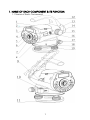
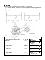
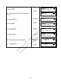
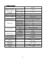
e
D
w ocu
w m
w
.k en
ol to
ln d
er e
la sc
br ar
an ga
a. do
cl
d
USER MANUAL
digital level DL-200
CONTENTS
D
w ocu
w m
w
.k en
ol to
ln d
er e
la sc
br ar
an ga
a. do
cl
d
e
FOREWORDS ............................................................................................... 3
PRECAUTIONS: ............................................................................................. 4
SAFETY GUIDE .............................................................................................. 5
OPERATOR................................................................................................... 6
DECLARATION OF EXCEPTIONAL RESPONSIBILITY ........................................... 6
1. NAME OF EACH COMPONENT & ITS FUNCTION ........................................ 7
1.1 Name of Each Component ......................................................... 7
1.2 Operation Keys & Functions ......................................................... 9
1.3 Display.......................................................................................... 9
2. PREPARATION FOR MEASUREMENT.......................................................... 10
2.1 Mounting the Instrument............................................................. 10
2.2 Power On.................................................................................... 11
2.3 Remaining Battery Display .......................................................... 11
2.4 Setting the Data Save Mode ...................................................... 12
2.5 Main Menu ................................................................................. 12
2.6 Staff Collimation and Focus ....................................................... 12
2.7 Surveying Note ........................................................................... 13
3. MEASURE ............................................................................................... 14
3.1 Measure Mode........................................................................... 14
3.2 S.O GH (Stake out Ground Height).............................................. 15
3.3 S.O HD (Stake out Height Difference).......................................... 16
3.4 S.O Dist (Stake out Distance)....................................................... 17
3.5 Leveling ...................................................................................... 18
3.6 GH&HD....................................................................................... 20
4. ADJUST .................................................................................................. 22
5. PARAMETER SETTING............................................................................... 24
6. DATA MANAGE ...................................................................................... 25
7. OTHER FUNCTIONS................................................................................. 26
7.1 Distance Display [DIST] ................................................................ 26
7.2 Inverse Staff Mode [-].................................................................. 26
7.3 Horizontal Angle Measurement .................................................. 26
7.4 Optical Distance Measure.......................................................... 26
8. BATTERY AND CHARGER ......................................................................... 27
9. CIRCULAR VIAL ADJUSTMENT .................................................................. 27
10. TRANSPORTATION, STORING AND CLEANING ........................................ 27
11. SPECIFICATION .................................................................................... 29
2
FOREWORDS
Congratulations on your purchasing the Digital Level DL-202. In order to operate
this instrument correctly, please read this user manual carefully and keep it well so
as to refer to it easily in the future. Before use, please check the standard features
and make sure all the equipments and accessories are available.
D
w ocu
w m
w
.k en
ol to
ln d
er e
la sc
br ar
an ga
a. do
cl
d
e
In order to facilitate reading, some pictures are simplified.
3
PRECAUTIONS:
D
w ocu
w m
w
.k en
ol to
ln d
er e
la sc
br ar
an ga
a. do
cl
d
e
Before using this instrument, please make sure that each function is running well.
●Avoid to make the surface of the digital staff as well as the joints between
each section dirty or damaged, otherwise it will influence the accuracy of
reading and measurement. This is because the instrument needs to transfer
the black & white bar code to electric signal. That’s why in case the digital
staff is dirty, the accuracy would be decreased, or even the instrument is not
able to measure.
●Tripod
The digital level should be mounted on wooden tripod. Metal tripod is lighter
and it’s easy to shake, which will affect the accuracy. Each leg of the tripod
should be fixed well by screws.
●Tribrach
In case the tribrach is installed not properly, the accuracy would be influenced.
Please inspect the adjusting screw on the tribrach frequently and make sure
the central fixing screw is tightened.
●Packing well to avoid the instrument shaked
As an precise instrument, the digital level should be handled carefully to avoid
shaking and crashing during transportation. Severe shaking would damage
the measurement functions. When packing the instrument in the case, make
sure it is powered off and take off the battery.
●Carry the instrument carefully
When you need to move the instrument, you must grasp the lifting handle and
take it off from the tripod.
●Avoid to expose the instrument in sun, rain or humid condition
Leaving the instrument in place of high temperature (+50℃) would damage
the instrument. Do not shoot the sun with the objective lens, otherwise the
spare parts inside the instrument may be damaged.
●Avoid a great change on temperature
A great change on instrument temperature would decrease the measuring
range. For example, when the instrument is moved out from a hot car, please
leave the instrument to adapt to the surrounding temperature before use.
●Battery Inspection
Check the remaining battery before use.
●Digital Staff
Wear a glove when using a digital staff.
4
SAFETY GUIDE
D
w ocu
w m
w
.k en
ol to
ln d
er e
la sc
br ar
an ga
a. do
cl
d
e
Serious injury or even death may occur if the following cautions are ignored.
●In case of explosion, do not place the instrument close to inflammable gas,
liquid, or solid. Do not operate it in coal mine or dusty place.
●Do not disassemble or repair the instrument without authorization in case of
possible dangers occurred like fire, electric shock or damage. Disassembling
and maintenance are only implemented by the manufacturer and its
authorized service providers.
●Do not use the telescope to sight at the sun or sunlight that are refracted by
reflectors like prisms in case of any hurt to the eyes.
●Be careful to operate the instrument with the digital staff near high voltage
cables or transformers, in case of electric shock accident.
●Do not use the digital staff when there are thunder and lightning in case of
electric shock.
●Do not use chargers and batteries that are produced by a third party in case
of fire.
●Do not use a broken power supply, wires, sockets and plugs in case of fire or
electric shock.
●Do not use humid batteries or chargers in case of fire or electric shock.
●Do not place the batteries in fire or high-temperature environment in case of
explosion or damage.
●Do not use the power supply mentioned in the manuals of non-manufacturers
in case of fire or electric shock.
●Avoid short circuit when storing the batteries in case of fire.
●Do not disassemble or assemble the instrument or operate the plug with wet
hands in case of electric shock.
●Do not cover the charger when it is charging in case of fire.
●Do not touch the liquid leaked from the battery in case of hurt by the harmful
chemicals. And please change the battery.
●Injury to persons or damage to goods may occur if the following cautions are
not followed by operators.
●Harm: means hurt, burn, electric shock, etc.
●Damage: means serious damage caused to building, instrument or furniture.
●Overturning the instrument case may damage the instrument.
●Do not stand or sit on the case.
●Do not use the instrument case with broken belt, buckle, hinge, or lifting
handle, in case that the instrument is damaged or it hurts the legs if the case
falls.
●When mounting or delivering the instrument, please be careful that the leg tips
of the tripod may hurt people.
●Please make sure to mount the tribrach correctly. Serious damage will occur if
the tribrach falls from the tripod.
●When mounting the instrument on the tripod, make sure the central fixing
screw is tightened well to prevent the instrument from falling from the tripod.
●When mounting the instrument, make sure the screws of the tripod are
tightened well.
●When moving the tripod, make sure the screws of the tripod are tightened
5
well.
OPERATOR
●This instrument is only operated by specific persons.
It is required that the operator should be a qualified surveyor. Before operation,
inspection and calibration, operators should be acknowledged the safety
guide.
●During using the instrument, please wear necessary suits for protection (e.g.
safety shoes, safety helmet).
●Do not place the instrument directly on the ground. If the operator has to
leave the instrument alone, please cover the instrument with a nylon cover (if
available).
DECLARATION OF EXCEPTIONAL RESPONSIBILITY
D
w ocu
w m
w
.k en
ol to
ln d
er e
la sc
br ar
an ga
a. do
cl
d
e
●Users of this product should read the user manual thoroughly and implement
periodical inspection to the performance of the instrument.
●Manufacturer and its dealers shall not be responsible for any direct or indirect
consequences and profit loss resulted from destructive or intentional improper
use.
●Manufacturer and its dealers shall not be responsible for any direct or indirect
consequences and profit loss resulted from natural calamities (e.g.
earthquake, hurricane, flood, etc.), fire, accidents, or fault of a third party.
●Manufacturer and its dealers shall not be responsible for failure to operate
resulted from the fact that the data is changed or lost, or that operation is
interfered.
●Manufacturer and its dealers shall not be responsible for any consequences
and profit loss resulted from extra use without following the user manual.
●Manufacturer and its dealers shall not be responsible for any consequences
and profit loss resulted from improper transportation or connecting with other
products.
6
1. NAME OF EACH COMPONENT & ITS FUNCTION
D
w ocu
w m
w
.k en
ol to
ln d
er e
la sc
br ar
an ga
a. do
cl
d
e
1.1 Name of Each Component
7
battery
rough collimator
LCD display
keyboard panel
keys
eyepieces: use for adjusting the definition of the crosshair.
protecting cover of eyepieces: by releasing this cover, you can implement
the mechanical adjustment of the reticle in order to correct the optical
collimation line error.
8 data transfer port: connecting with PDA or computer.
9 reflector of circular vial
10 circular vial
11 tribrach
12 lifting handle
13 model label
14 objective lens
15 focusing hand wheel: use for focusing of digital staff.
16 power/measure key: use for instrument power ON/OFF, and measure.
17 horizontal tangent hand wheel
18 horizontal dial: use for setting the horizontal direction value of the collimating
direction to 0 or other required values.
19 leveling screws of the tribrach
D
w ocu
w m
w
.k en
ol to
ln d
er e
la sc
br ar
an ga
a. do
cl
d
e
1
2
3
4
5
6
7
8
1.2 Operation Keys & Functions
key
name
POW/MEAS
↑↓
→←
menu
distance
measure
select
number moving
ENT
ESC
enter
ESC
Power ON/OFF, and start to measure.
Power ON: press once;
Power OFF: hold on for 2 seconds.
Return to the menu list.
In measurement status, press it to start measure
the distance and display the distance.
Turn the page of menu list or data list.
Turn the left or right page when viewing the
data, or move left or right in inputting status.
To confirm the parameters or inputting data.
To escape from menu mode or any setting
mode. Also to go backspace to delete a
character in inputting mode.
Inputting numbers.
Use for inputting inverse staff. Set the inverse
staff. You should activate this function in
parameter setting first.
Turn ON/OFF the illumination
0~9
-
D
w ocu
w m
w
.k en
ol to
ln d
er e
la sc
br ar
an ga
a. do
cl
d
e
MENU
DIST
Power ON/OFF
measure
function
number keys
Mode of setting
inverse staff
illumination
.
decimal point
Inputting a decimal point
1.3 Display
The display adopts dot matrix LCD, displaying 2 lines, with 16 characters in each.
LCD illumination ON/OFF.
By pressing
to turn ON or OFF the illumination. It is also available to set it in
instrument parameters.
Setting Contrast
There’re 9 degrees for the contrast. Please refer to parameter setting to know how
to set the contrast.
9
2. PREPARATION FOR MEASUREMENT
2.1 Mounting the Instrument
Placing the Tripod.
Type E aluminum tripod with flat or dome head tripod is required.
(1) Adjust the three legs of the tripod to a proper length and tighten the fixing
screws at the middle of the leg.
(2) Tighten the hexagonal nut on the head of the tripod in order to make the
tripod legs not too loosen. Place the tripod on a certain point, expand the legs
until the distance between each leg is about 1m. First, fix a leg, and move the
other 2 legs to make the head of the tripod approximately leveled. If necessary,
adjust the length of the tripod legs.
(3) Trample the legs into the earth or fix it well on the ground.
D
w ocu
w m
w
.k en
ol to
ln d
er e
la sc
br ar
an ga
a. do
cl
d
e
Putting the Instrument on the Head of the Tripod.
Take out the instrument from the case carefully and place it on the head of the
tripod.
(1) Aim the tripod central screw to the center of the tribrach center and tighten
the screw until it is fixed at the head of the tripod.
(2) If you need to define an angle or a line through the horizontal dial, you
should center the instrument precisely with a plummet.
(3) Center the circular bubble by adjusting the three leveling screws of the
tribrach. If you are using a dome headed tripod, you should slightly loosen the
tripod central screw and rotate the instrument round the head of the tripod until
the circular bubble is centered, then tighten the screw.
Mounting the Instrument on a Certain Point (centering)
If you need to measure an angle or alignment, please precisely center the
instrument at a certain point with a plummet.
(1) Hang the plummet at the plummet hook of the central screw of the tripod.
(2) Adjust the plummet line to a proper height.
(3) In case the instrument is not centered at the known point, you can move the
instrument to that point without changing the position relationship between the
tripod leg and its head. First, put the tripod on the known point approximately
until the plummet is about 1cm away from the point. Second, grasp two legs of
the tripod and adjust the tripod by the third leg until the head of tripod is
leveled approximately with a proper height. Expand the legs of the tripod and
fix it on the ground.
(4) Finally, observe the plummet and the hook and trample the legs into the
ground.
(5) Slightly loosen the central screw of the tripod and move the instrument on
the head until the plummet is centered at the known point. Tighten the tripod
central screw.
Leveling the Instrument
Center the circular bubble by adjusting the tribrach screw.
First, put the tribrach as the below picture shown. Rotate 2 screws at the same time
in opposite direction until the bubble moves to a position where the line between
10
D
w ocu
w m
w
.k en
ol to
ln d
er e
la sc
br ar
an ga
a. do
cl
d
e
the bubble and screw C is perpendicular to the line between screw A and B (refer
to Picture A). Then rotate the screw C to move the bubble to the center of the
central circle. This procedure should be repeated for times until the bubble is
centered on any directions.
Picture A
Notice: Do not touch the telescope during leveling.
Picture B
Collimating and Focusing
(1) Sight at the digital staff with the rough collimator.
(2) Rotate the eyepiece slowly until the image of the crosshair becomes clear.
(3) Rotate the focusing hand wheel until the image of digital staff becomes
clear. Rotate the horizontal tangent to move the image of the staff to the
center of the vertical hair of the crosshair.
(4) Observe through the eyepiece. Move your eye slightly up, down, left and
right to check whether the relative position between the crosshair and the
image of the staff is not changed. If not, please return to step 1.
Notice: Measurement accuracy may be influenced if the crosshair and focusing is
not clear.
2.2 Power On
Press the power key (POW/MEAS).
2.3 Remaining Battery Display
The battery symbol indicates the remaining battery.
battery symbol
Menu
►1. Measure
full
sufficient
11
half
battery low. Please change anther battery or charge the battery.
unable to measure. The power will be cut off soon. You need to change the
battery.
2.4 Setting the Data Save Mode
In order to save the measurement data into the internal memory of the instrument,
before leveling measurement, the data saving mode should be set to auto save,
as the default setting is “OFF”.
2.5 Main Menu
1st Menu
2nd Menu
3rd Menu
4th Menu
e
Measure Mode
D
w ocu
w m
w
.k en
ol to
ln d
er e
la sc
br ar
an ga
a. do
cl
d
S.O GH
Measure
Stake out
S.O HD
S.O Dist
Leveling
GH&HD
Adjust
Meas.Mode
Meas Para.
Menu
Set
Ins. Para.
Min.Reading
Inverse Mode
Display Unit
Save Mode
Auto OFF
Contrast
Backlight
Ins.Info
Regis.Info
1.N Times
2.Continuous
1 mm/0.5mm
Not Use/Use
m(meter)/ft(US. Ft)
OFF/Auto/Manual save
On/Off
Off/On
Input PN
Search
Data Manage
Delete Job
Input PN/StdMeasData/
LvMeasData/GH/HD Data
Input PN/StdMeasData/
LvMeasData/GH/HD Data
Check Capa.
File Output
Input PN/StdMeasData/
LvMeasData/GH/HD Data
Format
2.6 Staff Collimation and Focus
(1) Focusing
Adjust the eyepiece focusing screw until the crosshair can be seen clearly. Then
adjust the focusing screw until you can see the staff clearly through the objective
lens.
12
A precise focusing can shorten the measuring time and improve the accuracy.
Measurement of high accuracy requests precise focusing as well as continuous
measures.
(2) Obstacles
Measurement can be implemented if the staff is blocked less than 30%. Even if the
crosshair center is blocked, as long as the field of view is blocked less than 30%,
measurement still can be implemented. However, in this case, the accuracy might
be affected.
(3) Shadow
The surveying accuracy may be influenced if the staff is covered by shadow. In
some cases, it is not possible to measure.
D
w ocu
w m
w
.k en
ol to
ln d
er e
la sc
br ar
an ga
a. do
cl
d
e
(4) Backlight
If the background of the staff is too bright, which affects the contrast of the staff,
the digital level might not be able to measure. You can cover something ahead of
the objective lens in order to reduce the background light invading to the lens.
When a strong light comes into the eyepiece, it might not be able to measure
either. You can also cover the eyepiece in order to block the strong light from
coming into the eyepiece.
When the sun is in a low position (for example, in the morning or at night fall), or if
the sun light comes into the objective lens directly, it is suggested to block the
sunlight with hands.
2.7 Surveying Note
In order to make full use of the functions of instrument, please pay attention to the
following:
(1) Set up the staff in bright place. If possible, prolong the staff completely. If
illumination is employed, it is suggested to illuminate the whole staff, otherwise the
accuracy might be affected.
(2) The shortest distance between instrument and staff is 1.5m.
(3) It won’t affect the digital level to measure if the staff is blocked. But if the
bar code on the staff is blocked by tree branches or leaves, the digital level might
display error, or the accuracy is influenced.
(4) If an error occurs because the place where the staff is put is darker than
that of the eyepiece, you are suggested to block the light for the eyepiece.
(5) Deflection and pitching of the staff may affect the accuracy. During the
measurement, make sure the staff is paralleled to the vertical hair of the reticle.
The staff should be unfolded completely and fixed well. Make sure the joints of the
staff are well and precise. Avoid to measure through the glass window.
(6) After a long storage or transportation, check and calibrate the digital and
optical sight errors. Then adjust the circular vial and keep the optical parts clean.
13
3. MEASURE
3.1 Measure Mode
This mode is to measure the staff reading and distance without calculating the
height. Refer to “Set” to set the measure times. Using the average value upon
several times can improve the accuracy.
Operation Procedure
Operation
Display
1. Press [ENT]
[ENT]
Menu
►1.Measure
2. Press [▲] or [▼] to select the
Measure Mode and press [ENT].
[ENT]
►1.Measure Mode
2.Stake out
↓
3. If the saving mode is set to Auto
save or Manual save:
[ENT]
↓
Job Name?
=>B1_
↓
Standard Mode
Press MEAS
↓
Rod: 0.8050m
Dist: 8.550m
↓
e
Save Data?
Y:ENT N:ESC
D
w ocu
w m
w
.k en
ol to
ln d
er e
la sc
br ar
an ga
a. do
cl
d
[1]
[ENT]
4. Input the job name and press [ENT].
5. Collimate the staff until it looks clear
and press [MEAS] to measure. The last
value after several measures is the
average value. Under continuous
measure, press [ESC] to stop and
record.
6. Press [▲] [▼] to view the point. After
saving, the point number will be
increased automatically.
[MEAS]
[▲] [▼]
7. Press [ENT] to confirm or [ESC] to
quit.
[ENT] to
continue or
[ESC] to
quit.
8. In any process, press [ESC]
continuous to return to main menu.
[ESC] to
quit
14
↓
Pn Num: P
1
Standard Mode
Press MEAS
↓
↓
3.2 S.O GH (Stake out Ground Height)
Under this mode, user can stake out by inputting the ground heights (GH) of
backsight point and stakeout point.
Operation Procedure
Operation
Display
1. Press [ENT]
[ENT]
Menu
►1.Measure
2.Press [▲] [▼] to select “2.Stake out”
and press [ENT].
[ENT]
1.Measure Mode
►2.Stake out
↓
3.Select “S.O GH” (stake out ground
height) and press [ENT].
[ENT]
►1.S.O GH
2.S.O HD
↓
D
w ocu
w m
w
.k en
ol to
ln d
er e
la sc
br ar
an ga
a. do
cl
d
e
↓
Input BS
height
BS GH?
=100_
m
↓
Input BS
height
SO GH?
=101_
m
↓
6. Collimate the staff on backsight point
until it looks clear and press [MEAS].
[MEAS]
Meas BS Pt
Press MEAS
7. It displays the backsight staff and the
distance. Press [MEAS] to measure
continuously or press [ENT] to go to
next step, or press [ESC] to quit.
[ENT]
8.Collimate the staff on stakeout point
until it looks clear and press [MEAS].
[MEAS]
or
[ENT]
or
[ESC]
4. Input the ground height of the
backsight point and press [ENT].
5. Input the ground height of the
stakeout point and press [ENT].
It displays the stakeout rod reading and
the distance. Press [ENT] to display the
height and the value to fill or dig. “-”
means to fill and “+” means to dig.
9. Press [ENT] to continue to stake out
or press [ESC] to quit.
15
↓
BRod: 0.8050m
BDist: 8.550m
Meas SO Pt
Press MEAS
↓
SRod: 0.6540m
SDist: 7.633m
↓
GH: 1.0300m
HD: -3.9705m
↓
ENT: Continue
ESC: New Meas
↓
3.3 S.O HD (Stake out Height Difference)
User can stake out by inputting the HDs (height differences) of the backsight point
and the stakeout point.
Operation Procedure
Operation
Display
1. Press [ENT].
[ENT]
Menu
►1.Measure
2.Press [▲] or [▼] to select “layout”
and press [ENT].
[ENT]
1.Measure Mode
►2.Stake out
↓
3.Select Margin Out and press [ENT].
[ENT]
4. Input the GH (ground height) of
backsight point and press [ENT].
Input BS
height
[ENT]
5. Input the HD (height difference) of
the stakeout point and press [ENT].
Input VH
of stakeout
point
[ENT]
1.S.O GH
主菜单
►2.S.O HD
►测量
7. It displays the backsight rod reading
and the distance. Press [MEAS] to
measure continuously or press [ENT] to
go to next step, or press [ESC] to quit.
8.Collimate the staff on stakeout point
until it looks clear and press [MEAS].
It displays the stakeout rod reading and
the distance. Press [ENT] to display the
height and the value to fill or dig.
“-“ means to fill and “+” means to dig.
9. Press [ENT] to continue to stake out
or press [ESC] to quit.
16
[MEAS]
[ENT]
[MEAS]
or
[ENT]
or
[ESC]
↓
e
D
w ocu
w m
w
.k en
ol to
ln d
er e
la sc
br ar
an ga
a. do
cl
d
6. Collimate the staff until it looks clear
and press [MEAS].
↓
BS GH?
=100_
m
SO HD?
=1_
m
Meas BS Pt
Press MEAS
BRod: 0.8050m
BDist: 8.550m
Meas SO Pt
Press MEAS
SRod: 0.6540m
SDist: 7.633m
GH: 1.0300m
HD: -3.9705m
[ENT]
ENT: Continue
ESC: New Meas
3.4 S.O Dist (Stake out Distance)
User can stake out by inputting the distance.
Operation Procedure
Operation
1. Press [ENT].
Display
Menu
►1.Measure
[ENT]
2.Press [▲] or [▼] to select “S.O Dist”
(stake out distance) and press [ENT].
[ENT]
↓
1.Measure Mode
►2.Stake out
[▼]
[ENT]
↓
►3.S.O Dist
Input the
distance
[ENT]
4. Collimate the staff until it looks clear
and press [MEAS].
[MEAS]
D
w ocu
w m
w
.k en
ol to
ln d
er e
la sc
br ar
an ga
a. do
cl
d
3.Input the distance of stake out point
and press [ENT].
e
↓
5. Displays the distance and the
difference. Press [MEAS] to measure
continuously or press [ENT] to go to
next step, or press [ESC] to quit.
When the ∆Rod is positive, it indicates
to move the staff backward. When the
∆Rod is negative, it indicates to move
the staff forward.
17
[ENT]
Input Dist?
=50_
m
S.O Dist
Press MEAS
Dist: 30.00m
∆Rod : 20.00m
ENT: Continue
ESC: New Meas
3.5 Leveling
In Leveling mode, the saving mode should be set to “Auto” or “Manual save”. In this
session we set it Auto Save.
Operation Procedure
Operation
Display
1. Press [ENT].
[ENT]
2.Press [▲] or [▼] to select “Leveling”
and press [ENT].
Menu
►1.Measure
[▼]
1.Measure Mode
►2.Stake out
[ENT]
4. Input the point number of backsight
point and press [ENT].
Input point
number
[ENT]
5.Select whether to use the existed
data.
[ENT]
e
Input job
name
[ENT]
►3.Leveling
4.GH&HD
D
w ocu
w m
w
.k en
ol to
ln d
er e
la sc
br ar
an ga
a. do
cl
d
3.Input the job name and press [ENT].
[ENT]
Job Name?
=>L54_
BS PN
=>P1_
Load data?
Y: ENT N: ESC
►T01
T02
[ENT]
6. Collimate the staff until it looks clear
and press [MEAS].
[MEAS]
8 . Press [►] or [◄] to choose to
measure FS (frontsight) point or
intermediate point (Int.Pt). Now choose
FS first.
BRod: 1.2125m
BDist: 8.575m
[►] or [◄]
[ENT]
Input point
18
G.H: 30.00m
Y:ENT N:ESC
Meas the BS Pt
PN:
P1
7. It displays the backsight staff and the
distance. Press [MEAS] to measure
continuously or press [ENT] to measure
next point.
↓
SelectPtType
►FS
Int
↓
↓
number
9.Input the point number of frontsight
point and press [ENT].
10. Collimate the staff until it is clear
and press [MEAS].
FS PN
=>P2_
[ENT]
Meas the FS Pt
PN:
P2
[MEAS]
FRod: 0.9550m
FDist: 8.486m
[►] or [◄]
[ENT]
e
Input point
number
[ENT]
SelectPtType
BS
►Int
D
w ocu
w m
w
.k en
ol to
ln d
er e
la sc
br ar
an ga
a. do
cl
d
11 . Press [►] or [◄] to choose to
measure BS (backsight) point or Int
(Intermediate point). Now choose
intermediate point.
.
12.Input the point number of the IntPt
and press [ENT].
[MEAS]
13. Collimate the staff until the staff is
clear and press [MEAS].
[ESC]
14. Press [ESC] and [ENT] to quit.
[ENT]
Int Pn
=>I2
Meas the Int Pt
PN:
I1
IRod: 0.7395m
IDist: 8.501m
ENT: Continue
ESC: New Meas
After measurement, below data will be displayed.
After measuring the backsight point, press [▲] or [▼] to show the following screen.
BRod:1.022m
BDist:15.07m
Measurement value of backsight point
G H:
21.555m
PN: P01
Ground height of backsight point
Point number of backsight point
When the current measurement finishes, press [▲] or [▼] to display the following
screen.
19
FRod:1.032m
FDist: 15.07m
Measurement value of front sight point
G H:
PN:
22.555m
P05
Ground height of front sight point
Point number of front sight point
H D:
∑:
0.532m
25.003m
Height distance of this station
Total length
D
w ocu
w m
w
.k en
ol to
ln d
er e
la sc
br ar
an ga
a. do
cl
d
e
When the measurement of interval point is finished, press [▲] or [▼] to display the
following screen.
IRod:1.022m
IDist: 15.07m
G H:
PN:
21.555m
P01
Measurement value of intermediate
point point
Ground height of intermediate point
Point number of intermediate point
Explanation about the middle point number of leveling measurement.
Before frontsight measurement you can change the point number. It starts with P
and 5 numbers following, which will be increased. Those point numbers that are
used can be used again.
3.6 GH&HD
This mode can measure the GH (ground height) or HD (height difference) of the
backsight point before measurement.
Operation Procedure
Operation
Display
1. Press [ENT].
[ENT]
2. Press [▲] or [▼] to select “GH&HD”
and press [ENT].
[▼]
20
Menu
►1.Measure
↓
1.Measure Mode
►2.Stake out
↓
3.Leveling
►4.GH&HD
↓
Input job
name
[ENT]
4. Input the job name and press [ENT].
5.Input the GH (ground height) of the
backsight point.
[ENT]
Job Name?
=>H5_
Input BS GH?
Y:ENT
N:ESC
BS GH?
=168.680m
D
w ocu
w m
w
.k en
ol to
ln d
er e
la sc
br ar
an ga
a. do
cl
d
Input point
number
[ENT]
Save Data?
Y: ENT N:ESC
e
[ENT]
3. Press [ENT] to save the data.
6. Collimate the staff until it looks clear
and press [MEAS].
[MEAS]
Meas BS Pt
Press MEAS
7. It displays the backsight rod reading
and the distance. Press [MEAS] to
measure continuously or press [ENT] to
measure next point.
[MEAS]
BRod: 0.841m
BDist: 10.005m
Meas FS Pt
Press MEAS
8. Collimate the staff on the front sight
point until it looks clear and press
[MEAS].
FRod: 0.841m
FDist: 10.005m
9. It displays the frontsight rod reading
and the its ground height and height
difference.
10. Press [ESC]
measurement.
to
restart
the
21
GH:168.479m
HD: -0.001m
[ESC]
Exit?
Y:ENT
N:ESC
4. ADJUST
D
w ocu
w m
w
.k en
ol to
ln d
er e
la sc
br ar
an ga
a. do
cl
d
e
Inspection of the collimating sight line (i angle) of the instrument.
(1) As Picture 1 displays, mount the instrument on a tripod between 2 staff which
is 50m away from each other. Divide the distance between A and B into 3 sessions
with the same distance.
(2) Level the instrument.
(3) Process:
Operation Procedure
Operation
[▲]or[▼]
[ENT]
1. Select “Adjust” in the menu and
press [ENT].
2. Press [MEAS].
3. Press [ENT].
4. Press [MEAS].
22
Display
Menu
►1.Measure
↓
►2.Adjust
3.Set
↓
[MEAS]
Adjust
a< ----A------b
[ENT]
Adjust
Aa Rod:0.801m
[MEAS]
Adjust
a ----A------ >b
Adjust
Ab Rod:1.023m
5.Press [ENT].
[ENT]
Relocate
A------------------ >B
You can power off the instrument and
move it.
6. Press [MEAS].
7.Press [ENT].
8. Press[MEAS].
[MEAS]
Adjust
a< ----B------b
[ENT]
Adjust
Ba Rod:0.808m
Adjust
a -----B------ >b
D
w ocu
w m
w
.k en
ol to
ln d
er e
la sc
br ar
an ga
a. do
cl
d
e
[MEAS]
9. Press [ENT].
10. Press [▲] or [▼] and [ENT].
11.Press [ENT].
23
[ENT]
Adjust
Bb Rod:1.030m
[▲]or[▼]
[ENT]
0.0000m
0”
[ENT]
0.0000m
0”
5. PARAMETER SETTING
Meas Para.
N Times/Continuous
1mm/0.5mm
Not Use/Use
m(meter)/ft(US. ft)
OFF/Auto/Manual save
On/Off
1~9
Off/On
Date/SN#
D
w ocu
w m
w
.k en
ol to
ln d
er e
la sc
br ar
an ga
a. do
cl
d
e
Ins.Para.
Meas.Mode
Min.Reading
Inverse
Mode
Display Unit
Save Mode
Auto OFF
Contrast
Backlight
Ins.Info
Regis.Info
Setting the measuring times of average measurement.
Operation Procedure
Operation
1. Press [▲] or [▼] and [ENT] to select
“Set”.
[▲]or[▼]
[ENT]
[ENT]
2.Press [ENT].
[▲]or[▼]
[ENT]
3.Press [▲] or [▼] and [ENT].
[ENT]
4.Press [ENT].
Press
times
[ENT]
5.Input the times and press [ENT].
24
Display
Menu
►1.Measure
↓
2.Adjust
►3.Set
↓
►Meas Para.
Ins.Para.
►1. Meas.Mode
2. Min.Reading
►1. N Times
2. Continuous
Meas Times?
N=1
(1-9)
Meas Times?
N=5
(1-9)
↓
6. DATA MANAGE
Operation Procedure
Operation
1. Press [▲] or [▼] to Data Manage.
Display
Menu
►1.Measure
[▲]or[▼]
[ENT]
↓
►4. Data Manage
↓
2. Press [ENT].
[ENT]
[▲] or [▼]
[ENT]
►1.Input PN
2.Search
↓
►3.Delete Job
4.Check Capa.
↓
►5.File Output
6.Format
↓
D
w ocu
w m
w
.k en
ol to
ln d
er e
la sc
br ar
an ga
a. do
cl
d
e
3. Press [▲] or [▼] and [ENT] to select.
Input Pn
User can input the point number and height to search for the base point in leveling
measurement.
Search
User can search for input point, standard measurement data, leveling
measurement data and GH/HD data.
Delete Job
User can delete input point, standard measurement data, leveling measurement
data and GH/HD data.
Check Capa.
User can check the capacity of the internal memory.
File Output
User can export the input point, standard measurement data, leveling
measurement data and GH/HD data to the computer. (Baud rate:9600, data
length:8, stop:1, no parity)
According to file types, user can add the extension following the rules below:
.L: leveling data
.M: measurement data
.H:GH/HD data
.T:input point data
Format:
User can format the internal memory.
25
7. OTHER FUNCTIONS
7.1 Distance Display [DIST]
Use the [DIST] to measure the distance before surveying, to make sure the
distances between the frontsight and backsight are same.
7.2 Inverse Staff Mode [-]
Under this model, staff can be inverted for the ceiling measure.
Firstly, set the “Inverse Mode” to “Use” in the Meas.Para. setting. Before pressing
MEAS, press the [-] button. The battery symbol and symbol “I” will appear alternately
on the upper right corner of the screen. That means the Inverse Mode is activated.
7.3 Horizontal Angle Measurement
D
w ocu
w m
w
.k en
ol to
ln d
er e
la sc
br ar
an ga
a. do
cl
d
e
This instrument is equipped with a horizontal dial which can be used for horizontal
angle measurement. Every 1° with a graduation, every 10° with a mark in the dial,
and the graduation increases from 0° to 350° in clockwise direction.
(1)First,set up and level the instrument in start point C. Second, sight the
telescope to backsight point A, and rotate the horizontal tangent screw until
crosshair is accurately on the staff at point A. Rotate the horizontal dial at 0°.
(2)Sight the telescope to point B, and adjust the horizontal tangent, until the
crosshair is accurately on the staff at point B. And the angle reading is angle
between target A and target B, i.e. ∠ACB.
7.4 Optical Distance Measure
With the stadia hair of the instrument and the graduation on the staff, you can
measure the distance easily. The stadia interval on the staff multiplies 100 is the
distance. The stadia interval is the interval between the upper hair and the lower
hair on the reticle.
(1) Set up the staff on the target point.
(2) Set up and level the instrument. Sight the telescope to the staff. Record the
stadia interval between upper hair and lower wire as “1”.
(3) The distance “L” between instrument and staff is L=100x1.
26
8. BATTERY AND CHARGER
The on-board battery is B-21.
Charging
(1) The output voltage of the charger is AC110V~220V. The electric current is
450mA.
(2) Red light means the battery is being charged. Green light means charging
is finished.
(3) It will take 5 hours to charge the battery.
D
w ocu
w m
w
.k en
ol to
ln d
er e
la sc
br ar
an ga
a. do
cl
d
e
Note: a. Charging should be in a temperature of 10℃~40℃
b. When the charging time exceeds the suggested charging time, the
battery life might be shortened.
c. The battery may discharge in storage. Inspect the battery before use if the
instrument is stored for a long time.
d. The battery should be stored in a temperature below 30℃, and should be
recharged every three or four months.
9. CIRCULAR VIAL ADJUSTMENT
1. Mount the instrument on a tripod. Center the circular vial precisely by rotating
the 3 tribrach screws.
2. Rotate the instrument 180°. If the bubble is not in the center, the circular vial
should be calibrated as follow:
a. Firstly, identify the bubble moving direction, and adjust the corresponding
screws to move the bubble half of the offset.
b. Level the circular vial with the 3 tribrach screws again.
c. rotate the instrument around again to check whether the bubble is centered
in every direction. If not, please repeat the steps a & b until the bubble is centered.
10. TRANSPORTATION, STORING AND CLEANING
Transportation
(1) In outdoor operation, the instrument should be stored in the carrying case,
or fixed on the tripod and carried on the shoulder. Make sure not to carry the
instrument upside down.
(2) In road transportation, do not leave too much space between instrument
cases. Normally, the instrument should be stored in a special case in road
transportation.
(3) In plane, train or ship transportation, the instrument should be stored in
original carrying case and carton.
(4) Delivering the battery: related law and rules should be totally understood.
Inform the carrier before the shipment.
27
Storage
(1) Notice the temperature when storing the instrument, especially the
temperature inside the car in hot summer.
(2) The battery should be removed if the instrument is going to be stored for a
long time.
(3) Do not store the wet instrument into the case before it is wiped dry.
D
w ocu
w m
w
.k en
ol to
ln d
er e
la sc
br ar
an ga
a. do
cl
d
e
Clean
(1) Clean the instrument after use.
a. If the instrument is wet by seawater, it should be wiped with a wet cloth
and then be dried by a dry cloth.
b. Wipe the dust on the instrument with a clean brush and a soft cloth. Do
not blow it with compressed air.
c. Wipe the dust on the objective lens with a clean brush, and wipe it with
cotton with mixture of alcohol and aether.
(2) When cleaning the plastic parts of the instrument, do not use volatile liquid
such as thinner and benzene. Neutral cleansing is suggested.
(3) Clean the staff after use, otherwise it will influence the accuracy. Do not use
volatile liquid such as thinner and benzene to clean the staff.
(4) Store the staff in safe place. It is suggested to cover the joints of the staff
with a cloth.
28
11. SPECIFICATION
DL-202
minimum display
digital reading
1.5mm
optic reading
2.0mm
digital reading
digital reading
HD
distance
D≤10m:10mm;D>10m:D*0.001
1.5m~100m
1mm/0.5mm
0.1/1cm
within 3s in normal condition
32×
measuring time
magnification
3″
1°20′
100
0
magnetic-damped
>±12′
0.50″/1′
16MB
increasing
mini-B
8′/2mm
5minutes/OFF
1º
LCD display of128*32dpi with
illuminator
D
w ocu
w m
w
.k en
ol to
ln d
er e
la sc
br ar
an ga
a. do
cl
d
resolving power
field of view
multi-constant
add-constant
type
range
accuracy
storage
point number
connection
accuracy
e
height accuracy
(standard deviation
for 1km double run
leveling)
distance accuracy
distance range
telescope
compensator
data storage
circular vial
auto power off
horizontal dial
graduation
display
temperature
tolerance
dimension
weight
-20℃~50℃
230 (L)×150 (W)×210mm(H)
2.5kg
29