1
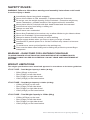
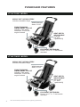
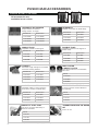
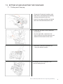
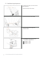
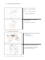
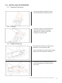
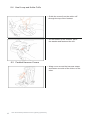
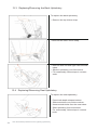
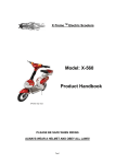
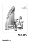
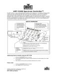
USER & WORKSHOP MANUAL
FOR THE
LIGHTNING
PUSHCHAIR
CONTENTS
1.0
2.0
3.0
4.0
5.0
6.0
7.0
8.0
Safety Rules . . . . . . . . . . . . . . . . . . . . . . . . . . . . . . . . . . . . . . . . . . . . . 3
Weight Limitations . . . . . . . . . . . . . . . . . . . . . . . . . . . . . . . . . . . . . . . 3
Pushchair Features . . . . . . . . . . . . . . . . . . . . . . . . . . . . . . . . . . . . . . . 4
Pushchair Accessories . . . . . . . . . . . . . . . . . . . . . . . . . . . . . . . . . . . . 6
Specifications Chart . . . . . . . . . . . . . . . . . . . . . . . . . . . . . . . . . . . . . . 7
Introduction . . . . . . . . . . . . . . . . . . . . . . . . . . . . . . . . . . . . . . . . . . . . . 8
Contact Information . . . . . . . . . . . . . . . . . . . . . . . . . . . . . . . . . . . . . . 8
Intended Use . . . . . . . . . . . . . . . . . . . . . . . . . . . . . . . . . . . . . . . . . . . . 8
Declaration Of Conformity . . . . . . . . . . . . . . . . . . . . . . . . . . . . . . . . . 8
Unpacking & Preparing The Pushchair For Use . . . . . . . . . . . . . . . . 8
Unfolding The Pushchair . . . . . . . . . . . . . . . . . . . . . . . . . . . . . . . . . . . 8
Setting Up & Adjusting The Pushchair . . . . . . . . . . . . . . . . . . . . . . . 9
7.1
Folding & Carrying . . . . . . . . . . . . . . . . . . . . . . . . . . . . . . . . . . . . 9
7.2
Seat Back Angle Adjustment . . . . . . . . . . . . . . . . . . . . . . . . . . . 10
7.3
Seat Depth Adjustment . . . . . . . . . . . . . . . . . . . . . . . . . . . . . . . . . 11
7.4
Footrest Height Adjustment . . . . . . . . . . . . . . . . . . . . . . . . . . . . . 12
7.5
Footplate Adjustment . . . . . . . . . . . . . . . . . . . . . . . . . . . . . . . . . . . 12
7.6
Adjusting & Using The Safety Harness . . . . . . . . . . . . . . . . . . . . 13
7.7
Brake System . . . . . . . . . . . . . . . . . . . . . . . . . . . . . . . . . . . . . . . . . 14
Installing Accessories . . . . . . . . . . . . . . . . . . . . . . . . . . . . . . . . . . . . . 15
8.1
Headrest Extension . . . . . . . . . . . . . . . . . . . . . . . . . . . . . . . . . . . . 15
8.2
Canopy . . . . . . . . . . . . . . . . . . . . . . . . . . . . . . . . . . . . . . . . . . . . . . 15
8.3
Padded Headrest . . . . . . . . . . . . . . . . . . . . . . . . . . . . . . . . . . . . . . 15
8.4
Heel Loop and Ankle Cuffs . . . . . . . . . . . . . . . . . . . . . . . . . . . . . . 16
8.5
Padded Harness Covers . . . . . . . . . . . . . . . . . . . . . . . . . . . . . . . . 16
Trunk Support . . . . . . . . . . . . . . . . . . . . . . . . . . . . . . . . . . . . . . . . . 17
Instructions For Transporting The Lightning Pushchair . . . . . . . . . 18
9.1
Prepare Lightning for Transportation . . . . . . . . . . . . . . . . . . . . . . 18
9.2
Attach the Set of Tie-Downs . . . . . . . . . . . . . . . . . . . . . . . . . . . . . 18
9.3
Assembly Instructions . . . . . . . . . . . . . . . . . . . . . . . . . . . . . . . . . . 18
9.4
Attach the Lightning Pushchair to Vehicle . . . . . . . . . . . . . . . . . 19
Instructions For Attaching The Work-N-Play Tray . . . . . . . . . . . . . . . 20
10.1
Contents . . . . . . . . . . . . . . . . . . . . . . . . . . . . . . . . . . . . . . . . . . . . . . . 20
10.2
Attaching and Removing the Tray . . . . . . . . . . . . . . . . . . . . . . . . . 20
Cleaning . . . . . . . . . . . . . . . . . . . . . . . . . . . . . . . . . . . . . . . . . . . . . . . . . . . 20
Maintenance . . . . . . . . . . . . . . . . . . . . . . . . . . . . . . . . . . . . . . . . . . . . . . . 21
Repair . . . . . . . . . . . . . . . . . . . . . . . . . . . . . . . . . . . . . . . . . . . . . . . . . . . . . 22
13.1
Front Wheel Assembly . . . . . . . . . . . . . . . . . . . . . . . . . . . . . . . . . . . 22
13.2
Rear Wheel Assembly . . . . . . . . . . . . . . . . . . . . . . . . . . . . . . . . . . . . 23
13.3
Replacing/Removing the Back Upholstery . . . . . . . . . . . . . . . . . . 24
13.4
Replacing/Removing the Seat Upholstery . . . . . . . . . . . . . . . . . . 24
Warranty . . . . . . . . . . . . . . . . . . . . . . . . . . . . . . . . . . . . . . . . . . . . . . . . . 25
8.6
9.0
10.0
11.0
12.0
13.0
14.0
2
User & Workshop Manual for the Lightning Upholstery
SAFETY RULES:
WARNING: Failure to follow these warnings and assembly instructions could result
in serious injury or death.
! Immediately discard any plastic wrapping.
! Never allow children to fold, assemble, or disassemble the Pushchair.
! Do not go over the weight capacity for the Pushchair. Excessive weight may
cause a hazardous, unstable condition if the approved load is exceeded.
! Never place child in Pushchair with their head forward and feet rearward.
! Avoid serious injury from falling or sliding out.
! Always use seat belt.
! Never leave user unattended.
! Never allow Pushchair to be used as a toy or allow children to give rides to others.
! Never use Pushchair if it becomes damaged.
! Always be aware of traffic around you when walking.
! Always engage brakes when you stop or when you let go of handle.
! Accessories or parcels placed in or on the Pushchair may cause it to become
unstable.
! To avoid burns, never put hot liquids in the working tray.
! Care must be taken when folding and unfolding the product to prevent finger
entrapment.
WARNING – RAINCOVER FOR LIGHTNING PUSHCHAIR
TO AVOID DANGER OF SUFFOCATION, RAINCOVER MUST BE ASSEMBLED WITH
OPTIONAL CANOPY AS PER ILLUSTRATION. DO NOT LEAVE USER UNATTENDED AT
ANY TIME.
WEIGHT LIMITATIONS
The weight specifications were tested and approved in accordance to the below guidelines
LT11/LT11SE – Total Weight Capacity is 86lbs (39.0kg)
• 66lbs (30kgs) on the seat.
• 5lbs (2.3kgs) on left side wheel.
• 5lbs (2.3kgs) on right side wheel.
• 10lbs (4.5kgs) on the lower basket.
LT14/LT14SE – Total Weight Capacity is 120lbs (54.4kg)
• 100lbs (45.5kgs) on the seat.
• 5lbs (2.3kgs) on left side wheel.
• 5lbs (2.3kgs) on right side wheel.
• 10lbs (4.5kgs) on the lower basket.
LT16/LT16SE – Total Weight Capacity is 150lbs (68kg)
• 100lbs (45.5kgs) on the seat.
• 5lbs (2.3kgs) on left side wheel.
• 5lbs (2.3kgs) on right side wheel.
• 10lbs (4.5kgs) on the lower basket.
User & Workshop Manual for the Lightning Upholstery
3
PUSHCHAIR FEATURES
LT11/LT11SE MODEL
HEAVY DUTY UPHOLSTERY
includes moldable ‘stays’
Width between
Arms 13 1/2”
FRONT RIGGING
SWING AWAY, FLIP-UP
Adjusts in the areasextension, Fore & Aft,
angle & lateral
SEAT DEPTH
ADJUSTABLE
1” to 12”
[15” with
optional Kit]
FOOTREST EXTENSION
From 1” to 12” in 1” increments
standard.
LT14/LT14SE MODEL
HEAVY DUTY UPHOLSTERY
includes moldable ‘stays’
Width between
Arms 16 1/4”
FRONT RIGGING
SWING AWAY, FLIP-UP
Adjusts in the areasextension, Fore & Aft,
angle & lateral
SEAT DEPTH
ADJUSTABLE
12” to 14”
[17” with
optional Kit]
FOOTREST EXTENSION
From 1” to 17” in 1” increments
standard.
4
User & Workshop Manual for the Lightning Upholstery
PUSHCHAIR FEATURES
LT16/LT16SE MODEL
HEAVY DUTY UPHOLSTERY
includes moldable ‘stays’
Width between
Arms 17 1/2”
FRONT RIGGING
SWING AWAY, FLIP-UP
Adjusts in the areasextension, Fore & Aft,
angle & lateral
SEAT DEPTH
ADJUSTABLE
16” to 18”
[21” with
optional Kit]
FOOTREST EXTENSION
From 1” to 17” in 1” increments
standard.
LT11/LT14/LT16 MODEL (Both Edition)
PUSH HANDLE
[ For pushing & control
of chair ]
LOCKING STRAP
[ To hold in folded position ]
FOLDING
ACTUATOR
CARRYING HANDLE
7000 SERIES ALUMINUM
is used for aircraft structural
members because of its
superb strength to weight
properties
WHEEL LOCKS
[ Operates both sides with single actuation ]
User & Workshop Manual for the Lightning Upholstery
5
PUSHCHAIR ACCESSORIES
UPHOLSTERY COLORS:
All accessories are
available in two colors.
Navy Blue
HEADREST EXTENSION
Simple Add-On or Remove
Design Adds 6” of Height
Red Item #
Blue Item #
LT11-RHRE
LT11-BHRE
LT14-RHRE
LT14-BHRE
LT16-RHRE
LT16-BHRE
SINGLE FLAP
Adjustable Lateral Trunk Support
Red Item #
Blue Item #
LT11-RSF
LT11-BSF
LT14-RSF
LT14-BSF
LT16-RSF
LT16-BSF
CANOPY
Extended Length w/Angle for Increased
Protection Viewing Window
Red Item #
Blue Item #
LT11-RCD
LT11-BCD
LT14-RCD
LT14-BCD
LT16-RCD
LT16-BCD
Red Glow
HEADREST
Padded, Contoured w/Lateral Wings
Red Item #
Blue Item #
LT11-RHR
LT11-BHR
LT14-RHR
LT14-BHR
LT16-RHR
LT16-BHR
DOUBLE FLAP
Adjustable Lateral Trunk Support w/
Double Pads
Red Item #
Blue Item #
LT11-RDF
LT11-BDF
LT14-RDF
LT14-BDF
LT16-RDF
LT16-BDF
HEEL LOOPS
& ANKLE CUFFS
Soft, Stretch Fabric For Comfortable,
Firm Hold
Item #
LT11-BAC
LT14-BAC
LT16-BAC
HARNESS COVERS
Washable & Easy to Add or Remove
Soft, Fleece Covers w/Lateral Wing
w/ Velcro Closures Custom Made for
the Lightning
Red Item #
Blue Item #
Item #
LT11-RHC
LT11-BHC
LT11-RC
LT14-RHC
LT14-BHC
LT14-RC
LT16-RHC
LT16-BHC
LT16-RC
WORK ‘N’ PLAY TRAY
w/Turn-Up or Down Sides Easy to
Remove & Position
Item #
LT11-WT
LT14-WT
LT16-WT
6
WEATHER PROTECTOR
User & Workshop Manual for the Lightning Upholstery
TRANSPORTATION TIE DOWN
KIT
Item #: LT-TD
SPECIFICATIONS CHART
Specifications
11” Model
14” Model
16” Model
SEAT WIDTH
OUTSIDE CANES
12.75”
15.75”
16.75”
SEAT WIDTH
BETWEEN CANES
11”
14”
16”
OVERALL HEIGHT
PUSH HANDLE HEIGHT
36”
36”
38”
OVERALL LENGTH w/ FOOTPLATE
38”
42”
44”
OVERALL LENGTH w/o FOOTPLATE
31”
35”
37”
LENGTH WHEEL TO WHEEL
(maximum)
27”
27”
27”
SEAT TO FLOOR
20”@11” depth
21”@14” depth
22”
OVERALL WIDTH
19.5”
24”
25”
SEAT ANGLE (DUMP)
30°
30°
30°
BACK UPHOLSTERY
19.25”
24”
24.75”
SEAT TO FOOTREST *
BACK ANGLE SETTINGS
1” to 12”
1” to 17”
1” to 17”
85°, 90° & 95°
85°, 90° & 95°
85°, 90° & 95°
19.25”W x 19.25”D x 25.5”H
24”W x 19.25”D x 27.5”H
25”W x 16”D x 28”H
WEIGHT OF CHAIR
(without riggings)
25 lbs
27 lbs
28 lbs
WEIGHT CAPACITY
75 lbs
100 lbs
150 lbs
FOLDED DIMENSIONS
FRAME COLOR CHOICES
UPHOLSTERY COLOR CHOICES
SILVER
SILVER
SILVER
NAVY BLUE • RED GLOW
NAVY BLUE • RED GLOW
NAVY BLUE • RED GLOW
FRONT WHEELS
6”
6”
6”
REAR WHEELS
10”
10”
10”
HEADREST EXTENSION
ADDS 6” OF HEIGHT
ADDS 6” OF HEIGHT
ADDS 6” OF HEIGHT
WIDTH OF BACK SEAT
(tube to tube)
11” (outside - 12.75”)
14” (outside - 15.5”)
15” (outside - 16.75”)
SEAT TO TOP OF BACK
20.25” (upholstery)
25” to handle
24” (upholstery)
25” to handle
25” (upholstery)
28” to handle
7.25” x 5.4375”
7.25” x 5.4375”
7.25” x 5.4375”
2”
2”
2”
FOOTPLATE MOUNTS
(outside width)
15.75”
16”
17”
WIDTH BETWEEN ARMRESTS
13.5”
16.25”
17.5”
FOOTPLATE
FOOTPLATE ADJUSTMENT
(fore and aft)
10” to 12”
12” to 14”
16” to 18”
TUBING
7/8”
7/8”
7/8”
OVERALL LENGTH W/O RIGGINGS
26.5”
29.5”
34”
SEAT DEPTH
*(Standard extension range in 1” increments) • Note: The Lightning has been crash tested
User & Workshop Manual for the Lightning Upholstery
7
1.0
INTRODUCTION
This Owners Manual will outline the proper method and easy
handling of the Lightning Pushchair and gives instructions for the
required cleaning and maintenance.
To avoid damage caused by improper handling and to allow optimal
use of the Lightning Pushchair, please read the following instructions
thoroughly.
If you have further questions or problems, please contact your
healthcare provider.
2.0
CONTACT COMPANY FOR ANY CONCERNS
For Europe, contact the authorized representative below:
TENDERCARE LIMITED
P.O.BOX 3091 LITTLE HAMPTON, BN16 2WF
UNITED KINGDOM
PH: #44 (0) 1903 726161 FX: #44 (0) 1903 734083
3.0
INTENDED USE – RECOMMENDATIONS
(Source: Catalogue and index for orthopedic appliances of the health
insurance companies, FRG) Rehab buggies are indicated for the
transport of patients with severe disabilities – mainly children and
adolescents – who are unable to walk and or to move independently
in a wheelchair.
4.0
DECLARATION OF CONFORMITY
Stealth Products declares that this product conforms to the requirements
of the 93 / 42 / EEC Guidelines.
5.0
UNPACKING AND PREPARING THE PUSHCHAIR FOR USE
The original package contains the following components
Pushchair (folded)
Footrest Riggings (both Left & Right)
Owners Manual
Accessories as Ordered
After unpacking and checking you have all components and that they
are in good condition, carefully dispose of the packaging at your local
recycling centre.
6.0
FOR UNFOLDING THE PUSHCHAIR, PROCEED TO THE
FOLLOWING INSTRUCTIONS:
• Remove any transport straps or transport guards
• Grasp the Pushchair at the push handles and lift up.
• Lift up enough as to allow the left and right locking mechanism to
latch in place.
8
User & Workshop Manual for the Lightning Upholstery
7.0 SETTING UP AND ADJUSTING THE PUSHCHAIR
7.1 Folding and Carrying
• Grasp the Pushchair handles with
both arms, and depress the folding
locking mechanism with foot.
• Hold in the down position and push
the back forward toward the seat.
• Place the left side of the Pushchair
on the floor.
• On the right side, maneuver the
Velcro strap around the armrest and
fastened to the back of the chair.
• With care, pick the Pushchair up
using the plastic handle.
Illustration of the Pushchair in its
correct folding set-up.
User & Workshop Manual for the Lightning Upholstery
9
7.2 Seat Back Angle Adjustment
To adjust back angle, you must remove
back upholstery
• Remove the top Velcro strap.
• Remove the lower Velcro strap.
• Remove both left and right side
backrest tubes.
• The diagram to the right will show
three position adjustments.
position 1 = 95
position 2 = 90
position 3 = 85
10
User & Workshop Manual for the Lightning Upholstery
• Using a 10mm wrench, remove the
adjustment nut on both sides.
• Move to the desired angle position
and fasten the nuts with the 10mm
wrench.
7.3 Seat Depth Adjustment
• LT16 Adjustment = 16”-18” (406.4-457.2mm)
• LT14 Adjustment = 12”-14” (304.8-355.6mm)
• LT11 Adjustment = 10”-12” (254-304.8mm)
• Press release button and move For or
Aft for desired depth adjustment.
User & Workshop Manual for the Lightning Upholstery
11
7.4 Footrest Height Adjustment
• LT16 = 1”-17” (25.4-431.8mm)
• LT14 = 1”-17” (25.4-431.8mm)
• LT11 = 1”-12” (25.4-304.8mm)
• Remove the locking pin.
• Move the footrest to the desired
height location.
• And replace the locking pin.
7.5 Footplate Adjustments
The footrest will swing-away for easy use
and adjustment.
• Swing footplate out.
• Using a 10mm wrench, loosen the
bolts and move to desired location.
• Once desired location is achieved,
fasten both bolts before use.
12
User & Workshop Manual for the Lightning Upholstery
7.6 Adjusting and Using the Safety Harness
Adjusting the depth on the Crotch Strap
• With the button facing up, guide the
strap through the mid section of the
holder.
• Then guide the strap under and
over the crotch strap ring.
• Finally, adjust the strap to the desired
length and tighten the strap down.
Adjusting the depth on the Crotch Strap
• Remove both hand nuts from the back
of the Pushchair.
User & Workshop Manual for the Lightning Upholstery
13
• On the front of the Pushchair, remove
the top strap pins and place them
where needed.
• Once desired location is met,
replace both hand nuts and firmly
tighten.
Locking and unlocking the safety harness
• To lock, insert both left and right side
harness pins into push button slots.
• To unlock, press the “red” push button
and gently pull back.
7.7 Brake System
To engage brake
• With your foot press the brake lever
down. This will lock both rear wheels.
To disengage brake
• With your foot placed under the brake
lever, pull the lever up. This will unlock
both rear wheels.
14
User & Workshop Manual for the Lightning Upholstery
8.0 INSTALLING ACCESSORIES
8.1 Headrest Extension
• Insert the headrest extension rods
into the backrest accessory tubes.
8.2 Canopy
• Insert the canopy into the backrest
accessory tubes or (if headrest
extension is in place) insert into
headrest extension tube.
8.3 Padded Headrest
The headrest extension is required for
installation of the headrest pad.
• From the headrest, tie the loose strings
strings onto the headrest extension.
• Guide the Velcro strap through the
loop and fastened it to other side of
the strap.
User & Workshop Manual for the Lightning Upholstery
15
8.4 Heel Loop and Ankle Cuffs
• Guide the screw from the ankle cuff
through the top of the footrest.
• On the bottom of the footrest, place
the washer and fastened the nut.
8.5 Padded Harness Covers
• Wrap cover around the harness straps
and fasten one side of the Velcro to the
other.
16
User & Workshop Manual for the Lightning Upholstery
8.6 Trunk Support
• Place the trunk support on the front
of the Pushchair and fasten it around
the back set using the Velcro straps.
• On both sides, wrap the bottom
support flap Velcro straps around
the lower armrest tube.
• Using the loose strap, guide it
through both top support flap rings.
• Finally, guide the strap through its
own ring and wrap around behind
the lower supports flaps.
User & Workshop Manual for the Lightning Upholstery
17
9.0
INSTRUCTIONS FOR TRANSPORTING THE LIGHTNING
PUSHCHAIR
The Lightning Pushchair can be folded for transport in the luggage area
of the vehicle. The Lightning Pushchair has been successfully impact
tested and meets the requirements specified in ANSI/RESNA WC/Vol.1,
Section 19, 5.3., prior to May 2002. It may therefore be used as a vehicle
seat.
CAUTION: When used as a vehicle seat the following instructions must
be followed.
WARNING: ONLY A COMPETENT PERSON SHOULD INSTALL THE TRANSPORTATION
DEVICES
9.1 Preparing Lightning For Transport
9.1.1 Check that the child is correctly strapped in the seat using the
5-point harness. Check that the 5-point harness is properly adjusted.
9.1.2 During transportation the headrest extension must be fitted.
9.1.3 Remove the following if fitted: Work “N” Play Tray, Rain-hood,
Shopping Basket or Sun Canopy.
9.2 Attach The Set Of 4 Tie-Down Kit Brackets
This Instruction is specific to the attachment of Tie-Down hardware for the Lightning
Pushchair.
WARNING: FAILURE TO ATTACH THE HARDWARE AS DETAILED COULD LEAD TO
SERIOUS INJURY OR DEATH.
9.2.1 TOOLS
• 3/16” T-handle Allen.
9.2.2 CONTENTS
4 - Tie-Down assemblies and each include:
• 1 - Handle Threaded Clamp (HTC).
• 1 - Through Clamp (TC).
• 4 - 1/4-20 x 3/4” Socket Head Cap Screws
9.3 Assembly Instructions
9.3.1 Separate the 4 TCs from the HTCs by removing the four screws.
9.3.2 Apply adequate amount of Loctite to each screw.
9.3.3 Loosely position the HTC and the TC to the front left and right bars
as shown:
• LT14 & LT16 - (Fig. 1)
• LT11 - (Fig. 2)
9.3.4 Loosely position the HTC and the TC to the rear left and right bars
as shown:
• (Fig. 3)
9.3.5 Tighten all clamp screws to 100 inches pounds torque (metric: 11Nm).
18
User & Workshop Manual for the Lightning Upholstery
(Fig. 1) Front View
14” & 16” Pushchair
(Fig. 2) Front View
11” Pushchair
Through
Clamps
HandleThreaded
Clamps
Through
Clamps
(Fig. 3)
Rear View 11”, 14” & 16”
9.4 Attach The Lightning Pushchair To Vehicle
The Lightning must be attched to the vehicle using the Set of 4 Tie-Down
Brackets, and a 4-point wheelchair restraint with Karabiners.
Note: The Set of 4 Tie-Down Kit Brackets is available from
Tendercare Ltd. 4-point wheelchair restraints are manufactured
by Unwin Safety Systems.
• Position the assembly correctly in
the vehicle over the floor track with
the front of the Lightning facing
towards the front of the vehicle (in
the direction of travel).
Put the Brakes on.
• Attach the front restraints to the
floor track and the front Tie-Down
Brackets making sure they are in
line with the floor track. Attach the
rear restraints to the floor track and
the rear Tie-Down Brackets.
• Open the lever of the over centre
buckle and pull through the excess
webbing to tighten the belt. Snap
down lever to tension.
• To release the Lightning follow the
above instructions in reverse order.
User & Workshop Manual for the Lightning Upholstery
19
10.0
INSTRUCTIONS FOR ATTACHING THE WORK ‘N’ PLAY TRAY
The below instructions are for attaching the Work ‘n’ Play tray to the
Lightning Pushchair.
CAUTION: THE TRAYS HAVE BEEN RATED TO HOLD UP TO 6.8kgs
15lbs OF WEIGHT. DO NOT OVERLOAD.
WARNING: REMOVE THE TRAY WHEN TRANSPORTING USER IN A
MOVING VEHICLE.
10.1 Contents
• Plastic Tray
• 2 Locking Pins
10.2
Attaching And Removing The Tray
10.2.1 Place the tray on top of the armrest handles as shown on Fig. 1.
10.2.2 Insert a locking pin to both sides as shown on Fig. 2.
10.2.3 For removal, ensure that the tray is free from objects and release
the tray by removing both locking pins.
Fig. 1
Fig. 2
11.0
CLEANING
11.1 Frame
11.1.1 To clean the frame, wipe with a damp cloth and dry thoroughly.
11.1.2 For more stubborn stains wipe with a damp cloth and warm water.
in which a little mild soap has been dissolved. Dry thoroughly.
11.1.3 Never use furniture polish or any spirit to clean the frame.
11.2 Upholstery
11.2.1
11.2.2
11.2.3
11.2.4
Remove the seat and back upholstery from the Pushchair.
Remove the harness and support boards from the upholstery.
Machine wash in cold water on delicate cycle.
Dry cover thoroughly before re-assembly. Do not tumble dry.
11.3 H-Harness
11.3.1 Remove harness from Pushchair.
11.3.2 Wipe with a damp cloth and dry thoroughly. Do not tumble dry.
11.3.3 Do Not immerse in water or wash in a machine
20
User & Workshop Manual for the Lightning Upholstery
11.4 Accessories
11.4.1 Remove accessories from the Pushchair.
11.4.2 Wipe with a damp cloth and dry thoroughly.
12.0
MAINTENANCE
! Excessive exposure to the sun or heat could cause fading or warping
of parts.
! Should a problem be found when carrying out the regular checks, it should be
immediately reported to the issuing authority or Tendercare Ltd.
12.1 Routine Maintenance -
The users family can carry-out the following tasks. No tools required.
12.1.1
12.1.2
12.1.3
12.1.4
Always wipe the Pushchair dry. Never put it away damp. (daily)
Check operation of the brake, folding and reclining mechanisms (weekly).
Check condition of harness, stitching and buckle (weekly).
Clean frame when necessary (we suggest at least once a week).
12.2 Six Months Maintenance -
Someone who is a competent tradesman or repairer should only carry out this
work. If a major fault is found stop using the Pushchair until it has been corrected.
12.2.1 Fold and open the Pushchair. Check that all movements through the
folding range are free. Examine frame for any damage.
12.2.2 Examine upholstery and foot straps for wear and arrange for replacement
if necessary.
12.2.3 Examine nuts, bolts, pivots and frame plugs for tightness and general
condition
12.2.4 Examine brake assembly for wear, damage and correct operation.
12.2.5 Examine tires for sharp objects, cuts or splits.
12.2.6 Examine castor and wheel bearings and suspension for excessive wear.
12.2.7 Check castors and rear wheels for free rotation, security and accumulation of fluff and grit. Remove with a dry lint free cloth.
User & Workshop Manual for the Lightning Upholstery
21
13.0
REPAIR
Any items involved in an accident no matter how minor MUST BE
WITHDRAWN FROM SERVICE IMMEDIATELY AND REPLACED.
Key Points:
! Do not reuse Nyloc nuts. Always replace with a new Nyloc nut.
! Always use recommended components and parts available from
Tendercare Ltd.
! Do not modify or repair frame
13.1 Front Wheel Assembly
• Required items:
Wheel
Nut
Washer
Shoulder bolt
10mm wrench
• Insert the shoulder bolt from
outside the wheel caster, and
• Through the wheel, and
• To the inside wheel caster.
• Place the washer and nut on
the inside of the wheel caster.
• Then, tighten with necessary
tooling wrenches.
22
User & Workshop Manual for the Lightning Upholstery
13.2 Rear Wheel Assembly
• Required items:
Wheel
Nut
Washer
Shoulder bolt
10mm wrench
• Insert the shoulder bolt from the
outer part of the wheel
• Through the wheel, and
• To the inside wheel mount.
• Place the washer and nut on
the inside of the wheel caster.
• Then, tighten with necessary
tooling wrenches.
• Place the washer and nut on the
inside of the wheel mount.
• Then, tighten with necessary
tooling wrenches.
User & Workshop Manual for the Lightning Upholstery
23
13.3 Replacing/Removing the Back Upholstery
To replace the back upholstery,
• Remove the top Velcro strap.
• Remove the lower Velcro strap.
• Remove both left and right side backrest
tubes.
• Slip the upholstery out of the tubes.
• For reassembly, follow steps in reverse
order.
13.4 Replacing/Removing Seat Upholstery
To replace the seat upholstery,
• Press both depth release buttons.
•
•
•
•
24
User & Workshop Manual for the Lightning Upholstery
Slide seat tubes out of tube receiver.
Unscrew both bolts from the seat tubes.
Slide upholstery from seat tubes.
For reassembly, follow steps in reverse
order.
14.0
WARRANTY
For UK warranty claims contact Tendercare Ltd #44 (0) 1903 726161.
For all other warranty claims contact issuing authority.
14.1 The above will repair or replace free of charge, any parts or part found
to be defective due to manufacturer within a period of 12 months from
the date of delivery.
14.2 The above will not repair or replace free of charge any part or parts found
to be defective due to abuse, misuse or lack of correct maintenance.
14.3 Equipment for warranty claims should be returned in a strong carton.
There may be a charge for collection.
User & Workshop Manual for the Lightning Upholstery
25
P.O. Box 458 103 John Kelly Drive Burnet, TX 78611
phone: 1(800)965.9229
fax: 1(800)806.1225
e-mail: [email protected]
www.stealthproducts.com