1
Texas Instruments Home Computer
PC99
IBM PC emulator for the
Texas Instruments TI-99/4A
User Manual
Stage 6
TEXAS INSTRUMENTS
HOME COMPUTER
PC99
User Manual
Stage 6
Copyright © 1999-2000 CaDD Electronics
See important warranty information at back of book.
Release: 20000407
PC99 User Manual — Stage 6
Table of Contents
1. Quick start . . . . . . . . . . . . . . . . . . . . . . . . . . . . . . . . . . . . . . . . . . . . . . . . . . . . . . . . . . . . . . . . . . . . . . . . . .
1.1. Installation . . . . . . . . . . . . . . . . . . . . . . . . . . . . . . . . . . . . . . . . . . . . . . . . . . . . . . . . . . . . . . . . .
1.2. Configuration . . . . . . . . . . . . . . . . . . . . . . . . . . . . . . . . . . . . . . . . . . . . . . . . . . . . . . . . . . . . . . .
1.3. 99/4A emulator . . . . . . . . . . . . . . . . . . . . . . . . . . . . . . . . . . . . . . . . . . . . . . . . . . . . . . . . . . . . . .
1
1
2
2
2. Introduction . . . . . . . . . . . . . . . . . . . . . . . . . . . . . . . . . . . . . . . . . . . . . . . . . . . . . . . . . . . . . . . . . . . . . . . . . 3
2.1. Features . . . . . . . . . . . . . . . . . . . . . . . . . . . . . . . . . . . . . . . . . . . . . . . . . . . . . . . . . . . . . . . . . . . . 3
2.2. Additional features . . . . . . . . . . . . . . . . . . . . . . . . . . . . . . . . . . . . . . . . . . . . . . . . . . . . . . . . . . . 6
2.2.1. PC99 debugger . . . . . . . . . . . . . . . . . . . . . . . . . . . . . . . . . . . . . . . . . . . . . . . . . . . . . . 6
2.2.2. PC99 utilities . . . . . . . . . . . . . . . . . . . . . . . . . . . . . . . . . . . . . . . . . . . . . . . . . . . . . . . 7
2.2.3. PC99 disk utilities . . . . . . . . . . . . . . . . . . . . . . . . . . . . . . . . . . . . . . . . . . . . . . . . . . . 7
2.3. Features available by product . . . . . . . . . . . . . . . . . . . . . . . . . . . . . . . . . . . . . . . . . . . . . . . . . 10
2.4. Hardware requirements . . . . . . . . . . . . . . . . . . . . . . . . . . . . . . . . . . . . . . . . . . . . . . . . . . . . . . 11
2.5. Software requirements . . . . . . . . . . . . . . . . . . . . . . . . . . . . . . . . . . . . . . . . . . . . . . . . . . . . . . . 11
2.6. Terminology . . . . . . . . . . . . . . . . . . . . . . . . . . . . . . . . . . . . . . . . . . . . . . . . . . . . . . . . . . . . . . . 12
2.6.1. Keystrokes . . . . . . . . . . . . . . . . . . . . . . . . . . . . . . . . . . . . . . . . . . . . . . . . . . . . . . . . . 12
2.6.2. Hexadecimal values . . . . . . . . . . . . . . . . . . . . . . . . . . . . . . . . . . . . . . . . . . . . . . . . . 12
2.6.3. DOS commands . . . . . . . . . . . . . . . . . . . . . . . . . . . . . . . . . . . . . . . . . . . . . . . . . . . . 12
2.6.4. Disk Densities . . . . . . . . . . . . . . . . . . . . . . . . . . . . . . . . . . . . . . . . . . . . . . . . . . . . . . 13
2.6.5. Fast PC . . . . . . . . . . . . . . . . . . . . . . . . . . . . . . . . . . . . . . . . . . . . . . . . . . . . . . . . . . . 13
2.6.6. ASCII editor . . . . . . . . . . . . . . . . . . . . . . . . . . . . . . . . . . . . . . . . . . . . . . . . . . . . . . . 13
2.6.7. Protected mode . . . . . . . . . . . . . . . . . . . . . . . . . . . . . . . . . . . . . . . . . . . . . . . . . . . . . 13
3. Documentation . . . . . . . . . . . . . . . . . . . . . . . . . . . . . . . . . . . . . . . . . . . . . . . . . . . . . . . . . . . . . . . . . . . . . . 15
4. Supplied software . . . . . . . . . . . . . . . . . . . . . . . . . . . . . . . . . . . . . . . . . . . . . . . . . . . . . . . . . . . . . . . . . . . 16
5. Installation . . . . . . . . . . . . . . . . . . . . . . . . . . . . . . . . . . . . . . . . . . . . . . . . . . . . . . . . . . . . . . . . . . . . . . . . . 17
5.1. PC99 tree . . . . . . . . . . . . . . . . . . . . . . . . . . . . . . . . . . . . . . . . . . . . . . . . . . . . . . . . . . . . . . . . . . 18
6. Configuration . . . . . . . . . . . . . . . . . . . . . . . . . . . . . . . . . . . . . . . . . . . . . . . . . . . . . . . . . . . . . . . . . . . . . . .
6.1. General information about using CFG.EXE . . . . . . . . . . . . . . . . . . . . . . . . . . . . . . . . . . . . .
6.2. RS232 . . . . . . . . . . . . . . . . . . . . . . . . . . . . . . . . . . . . . . . . . . . . . . . . . . . . . . . . . . . . . . . . . . . . .
6.2.1. Display RS232 mapping . . . . . . . . . . . . . . . . . . . . . . . . . . . . . . . . . . . . . . . . . . . . .
6.2.2. Change RS232 mapping . . . . . . . . . . . . . . . . . . . . . . . . . . . . . . . . . . . . . . . . . . . . .
6.2.2.1. Select PC COM port to map TI RS232/1 to . . . . . . . . . . . . . . . . . . . . .
6.2.2.2. Select PC COM port hardware address . . . . . . . . . . . . . . . . . . . . . . . . .
6.2.2.3. Select PC COM port hardware interrupt . . . . . . . . . . . . . . . . . . . . . . .
6.2.3. Change PIO . . . . . . . . . . . . . . . . . . . . . . . . . . . . . . . . . . . . . . . . . . . . . . . . . . . . . . . .
6.2.3.1. Select PC LPT port to map TI PIO/1 to . . . . . . . . . . . . . . . . . . . . . . . .
6.2.3.2. Select PC LPT port hardware address . . . . . . . . . . . . . . . . . . . . . . . . .
24
25
26
27
27
28
28
29
30
30
30
TEXAS INSTRUMENTS
HOME COMPUTER
6.2.3.3. Select PC LPT port hardware interrupt . . . . . . . . . . . . . . . . . . . . . . . .
6.3. Sound . . . . . . . . . . . . . . . . . . . . . . . . . . . . . . . . . . . . . . . . . . . . . . . . . . . . . . . . . . . . . . . . . . . . .
6.3.1. Standard PC . . . . . . . . . . . . . . . . . . . . . . . . . . . . . . . . . . . . . . . . . . . . . . . . . . . . . . .
6.3.2. Sound Blaster . . . . . . . . . . . . . . . . . . . . . . . . . . . . . . . . . . . . . . . . . . . . . . . . . . . . . .
6.3.3. Display sound setting . . . . . . . . . . . . . . . . . . . . . . . . . . . . . . . . . . . . . . . . . . . . . . . .
6.3.4. Change sound setting . . . . . . . . . . . . . . . . . . . . . . . . . . . . . . . . . . . . . . . . . . . . . . . .
6.3.5. Sound Blaster . . . . . . . . . . . . . . . . . . . . . . . . . . . . . . . . . . . . . . . . . . . . . . . . . . . . . .
6.3.5.1. Display Sound Blaster status . . . . . . . . . . . . . . . . . . . . . . . . . . . . . . . . .
6.3.5.2. Display Sound Blaster register variables . . . . . . . . . . . . . . . . . . . . . . .
6.3.5.3. Change Sound Blaster register variables . . . . . . . . . . . . . . . . . . . . . . .
6.3.5.4. Display Sound Blaster noise variables . . . . . . . . . . . . . . . . . . . . . . . . .
6.3.5.5. Change Sound Blaster noise variables . . . . . . . . . . . . . . . . . . . . . . . . .
6.4. Joysticks . . . . . . . . . . . . . . . . . . . . . . . . . . . . . . . . . . . . . . . . . . . . . . . . . . . . . . . . . . . . . . . . . . .
6.4.1. Display joystick mapping . . . . . . . . . . . . . . . . . . . . . . . . . . . . . . . . . . . . . . . . . . . .
6.4.2. Change joystick mapping . . . . . . . . . . . . . . . . . . . . . . . . . . . . . . . . . . . . . . . . . . . .
6.4.2.1. Read new calibration values from joystick . . . . . . . . . . . . . . . . . . . . . .
6.4.2.2. Use old calibration values . . . . . . . . . . . . . . . . . . . . . . . . . . . . . . . . . . . .
6.4.2.3. Display old calibration values . . . . . . . . . . . . . . . . . . . . . . . . . . . . . . . .
6.4.3. Display joystick port . . . . . . . . . . . . . . . . . . . . . . . . . . . . . . . . . . . . . . . . . . . . . . . .
6.4.4. Change joystick port . . . . . . . . . . . . . . . . . . . . . . . . . . . . . . . . . . . . . . . . . . . . . . . .
6.4.5. Test joystick . . . . . . . . . . . . . . . . . . . . . . . . . . . . . . . . . . . . . . . . . . . . . . . . . . . . . . .
6.5. System . . . . . . . . . . . . . . . . . . . . . . . . . . . . . . . . . . . . . . . . . . . . . . . . . . . . . . . . . . . . . . . . . . . .
6.5.1. Display system variables . . . . . . . . . . . . . . . . . . . . . . . . . . . . . . . . . . . . . . . . . . . . .
6.5.2. Change system variables . . . . . . . . . . . . . . . . . . . . . . . . . . . . . . . . . . . . . . . . . . . . .
6.5.2.1. Change default debug mode . . . . . . . . . . . . . . . . . . . . . . . . . . . . . . . . . .
6.5.2.2. Change show startup info . . . . . . . . . . . . . . . . . . . . . . . . . . . . . . . . . . . .
6.5.2.3. Change VDP interrupt count . . . . . . . . . . . . . . . . . . . . . . . . . . . . . . . . .
6.5.2.4. Change delay value 1 . . . . . . . . . . . . . . . . . . . . . . . . . . . . . . . . . . . . . . . .
6.5.2.5. Change delay value 2 . . . . . . . . . . . . . . . . . . . . . . . . . . . . . . . . . . . . . . . .
6.5.2.6. Change illegal action response . . . . . . . . . . . . . . . . . . . . . . . . . . . . . . . .
6.5.2.7. Change CPU type . . . . . . . . . . . . . . . . . . . . . . . . . . . . . . . . . . . . . . . . . .
6.5.2.8. Change VDP type . . . . . . . . . . . . . . . . . . . . . . . . . . . . . . . . . . . . . . . . . .
6.5.2.9. Change speech quality . . . . . . . . . . . . . . . . . . . . . . . . . . . . . . . . . . . . . . .
6.5.2.10. Change Gramulator emulation . . . . . . . . . . . . . . . . . . . . . . . . . . . . . .
6.5.2.11. Set up mini screen . . . . . . . . . . . . . . . . . . . . . . . . . . . . . . . . . . . . . . . . .
6.5.3. Display overlay file . . . . . . . . . . . . . . . . . . . . . . . . . . . . . . . . . . . . . . . . . . . . . . . . . .
6.5.4. Change path of overlay file . . . . . . . . . . . . . . . . . . . . . . . . . . . . . . . . . . . . . . . . . . .
6.5.5. Select overlay file in \pc99\oly . . . . . . . . . . . . . . . . . . . . . . . . . . . . . . . . . . . . . . . . .
6.5.6. Creating an overlay file . . . . . . . . . . . . . . . . . . . . . . . . . . . . . . . . . . . . . . . . . . . . . .
6.5.7. Display delay units per clock tick . . . . . . . . . . . . . . . . . . . . . . . . . . . . . . . . . . . . . .
6.6. Disks . . . . . . . . . . . . . . . . . . . . . . . . . . . . . . . . . . . . . . . . . . . . . . . . . . . . . . . . . . . . . . . . . . . . . .
6.6.1. Texas Instruments Disk Controller . . . . . . . . . . . . . . . . . . . . . . . . . . . . . . . . . . . .
6.6.2. Guion Disk Controller . . . . . . . . . . . . . . . . . . . . . . . . . . . . . . . . . . . . . . . . . . . . . . .
6.6.3. Myarc Disk Controller . . . . . . . . . . . . . . . . . . . . . . . . . . . . . . . . . . . . . . . . . . . . . . .
31
32
32
32
33
33
34
34
34
35
37
37
40
40
41
42
42
43
43
43
43
45
46
46
47
48
49
49
50
50
51
51
51
52
52
54
54
54
54
56
57
57
57
58
PC99 User Manual — Stage 6
6.6.4. Using CFG.EXE to change disks . . . . . . . . . . . . . . . . . . . . . . . . . . . . . . . . . . . . . .
6.6.5. Using DOS COPY to change disks . . . . . . . . . . . . . . . . . . . . . . . . . . . . . . . . . . . . .
6.6.6. Copying disks . . . . . . . . . . . . . . . . . . . . . . . . . . . . . . . . . . . . . . . . . . . . . . . . . . . . . .
6.6.7. Display disk paths . . . . . . . . . . . . . . . . . . . . . . . . . . . . . . . . . . . . . . . . . . . . . . . . . .
6.6.8. Change disk paths . . . . . . . . . . . . . . . . . . . . . . . . . . . . . . . . . . . . . . . . . . . . . . . . . .
6.6.8.1. Change path for DSK1 . . . . . . . . . . . . . . . . . . . . . . . . . . . . . . . . . . . . . .
6.6.8.2. Display \PC99\DSK directory . . . . . . . . . . . . . . . . . . . . . . . . . . . . . . . . .
6.6.9. Change disk attached flags . . . . . . . . . . . . . . . . . . . . . . . . . . . . . . . . . . . . . . . . . . .
6.6.10. Change disk read/write flags . . . . . . . . . . . . . . . . . . . . . . . . . . . . . . . . . . . . . . . . .
6.6.11. Display disk catalog . . . . . . . . . . . . . . . . . . . . . . . . . . . . . . . . . . . . . . . . . . . . . . . .
6.6.11.1. Sector 0 information . . . . . . . . . . . . . . . . . . . . . . . . . . . . . . . . . . . . . . .
6.6.11.2. Disk Manager catalog . . . . . . . . . . . . . . . . . . . . . . . . . . . . . . . . . . . . . .
6.6.11.3. Disk Manager catalog files only . . . . . . . . . . . . . . . . . . . . . . . . . . . . . .
6.6.11.4. p-Code catalog . . . . . . . . . . . . . . . . . . . . . . . . . . . . . . . . . . . . . . . . . . . .
6.6.11.5. Plato catalog . . . . . . . . . . . . . . . . . . . . . . . . . . . . . . . . . . . . . . . . . . . . . .
6.6.12. Select Plato disk . . . . . . . . . . . . . . . . . . . . . . . . . . . . . . . . . . . . . . . . . . . . . . . . . . .
6.6.12.1. Creating compressed Plato disks . . . . . . . . . . . . . . . . . . . . . . . . . . . . .
6.6.13. Display cassette paths . . . . . . . . . . . . . . . . . . . . . . . . . . . . . . . . . . . . . . . . . . . . . .
6.6.14. Change cassette paths . . . . . . . . . . . . . . . . . . . . . . . . . . . . . . . . . . . . . . . . . . . . . .
6.6.14.1. Change path for CS1 . . . . . . . . . . . . . . . . . . . . . . . . . . . . . . . . . . . . . . .
6.6.15. The blank disks — FMT21.DSK and FMT22.DSK . . . . . . . . . . . . . . . . . . . . . .
6.6.16. The blank disks — PFMT21.DSK and PFMT22.DSK . . . . . . . . . . . . . . . . . . . .
6.6.17. TI or Guion vs. Myarc disk controller . . . . . . . . . . . . . . . . . . . . . . . . . . . . . . . . .
6.7. Keyboard . . . . . . . . . . . . . . . . . . . . . . . . . . . . . . . . . . . . . . . . . . . . . . . . . . . . . . . . . . . . . . . . . .
6.7.1. Joystick keys . . . . . . . . . . . . . . . . . . . . . . . . . . . . . . . . . . . . . . . . . . . . . . . . . . . . . . .
6.7.2. Special keys. . . . . . . . . . . . . . . . . . . . . . . . . . . . . . . . . . . . . . . . . . . . . . . . . . . . . . . .
6.7.3. Display path of keyboard file. . . . . . . . . . . . . . . . . . . . . . . . . . . . . . . . . . . . . . . . . .
6.7.4. Change path of keyboard file. . . . . . . . . . . . . . . . . . . . . . . . . . . . . . . . . . . . . . . . . .
6.7.5. Display key age value. . . . . . . . . . . . . . . . . . . . . . . . . . . . . . . . . . . . . . . . . . . . . . . .
6.7.6. Change key age value. . . . . . . . . . . . . . . . . . . . . . . . . . . . . . . . . . . . . . . . . . . . . . . .
6.8. Console . . . . . . . . . . . . . . . . . . . . . . . . . . . . . . . . . . . . . . . . . . . . . . . . . . . . . . . . . . . . . . . . . . . .
6.8.1. Display paths for console ROM and GROMs . . . . . . . . . . . . . . . . . . . . . . . . . . . .
6.8.2. Change paths for console ROM and GROMs . . . . . . . . . . . . . . . . . . . . . . . . . . . .
6.8.3. Configure 99/4A console ROM and GROMs . . . . . . . . . . . . . . . . . . . . . . . . . . . . .
6.8.4. Configure 99/4A v2.2 console ROM and GROMs . . . . . . . . . . . . . . . . . . . . . . . . .
6.8.5. Configure 99/4 console ROM and GROMs . . . . . . . . . . . . . . . . . . . . . . . . . . . . . .
6.8.6. Configure OPA SOB console ROM and GROMs . . . . . . . . . . . . . . . . . . . . . . . . .
6.8.7. Configure CDC console ROM and GROMs . . . . . . . . . . . . . . . . . . . . . . . . . . . . . .
6.9. Peripherals . . . . . . . . . . . . . . . . . . . . . . . . . . . . . . . . . . . . . . . . . . . . . . . . . . . . . . . . . . . . . . . . .
6.9.1. Display peripheral ROMs and GROMs . . . . . . . . . . . . . . . . . . . . . . . . . . . . . . . . .
6.9.2. Change peripheral ROMs and GROMs . . . . . . . . . . . . . . . . . . . . . . . . . . . . . . . . .
6.9.3. Display peripheral type . . . . . . . . . . . . . . . . . . . . . . . . . . . . . . . . . . . . . . . . . . . . . .
6.9.4. Change peripheral type . . . . . . . . . . . . . . . . . . . . . . . . . . . . . . . . . . . . . . . . . . . . .
6.9.4.1. Memory card . . . . . . . . . . . . . . . . . . . . . . . . . . . . . . . . . . . . . . . . . . . . . .
58
59
59
60
61
61
61
61
62
63
63
64
65
65
66
66
67
68
68
68
69
69
70
71
71
72
73
73
73
74
75
75
76
77
77
77
78
78
79
80
81
82
82
83
TEXAS INSTRUMENTS
HOME COMPUTER
6.9.5. Setup peripheral . . . . . . . . . . . . . . . . . . . . . . . . . . . . . . . . . . . . . . . . . . . . . . . . . . . . 85
6.9.5.1. Setup peripheral at CRU >1000 (Myarc 512K card) . . . . . . . . . . . . . 85
6.9.5.2. Setup peripheral at CRU >1100 (Disk Controller card) . . . . . . . . . . 85
6.10. Module . . . . . . . . . . . . . . . . . . . . . . . . . . . . . . . . . . . . . . . . . . . . . . . . . . . . . . . . . . . . . . . . . . . 86
6.10.1. Display loaded module names . . . . . . . . . . . . . . . . . . . . . . . . . . . . . . . . . . . . . . . . 87
6.10.1.1. Limitations of REVIEW MODULE LIBRARY feature . . . . . . . . . . . 88
6.10.1.2. Applications that do not read the GROM base address . . . . . . . . . . 88
6.10.2. Display loaded module files . . . . . . . . . . . . . . . . . . . . . . . . . . . . . . . . . . . . . . . . . . 89
6.10.3. Change module. . . . . . . . . . . . . . . . . . . . . . . . . . . . . . . . . . . . . . . . . . . . . . . . . . . . 89
6.10.3.1. Dummy module . . . . . . . . . . . . . . . . . . . . . . . . . . . . . . . . . . . . . . . . . . . 90
6.10.4. Check all modules (screen report). . . . . . . . . . . . . . . . . . . . . . . . . . . . . . . . . . . . . 90
6.10.5. Check all modules (disk report). . . . . . . . . . . . . . . . . . . . . . . . . . . . . . . . . . . . . . . 91
6.10.6. Change module count . . . . . . . . . . . . . . . . . . . . . . . . . . . . . . . . . . . . . . . . . . . . . . 91
6.10.7. Print module list . . . . . . . . . . . . . . . . . . . . . . . . . . . . . . . . . . . . . . . . . . . . . . . . . . 92
6.10.8. Set up Super Space bank . . . . . . . . . . . . . . . . . . . . . . . . . . . . . . . . . . . . . . . . . . . . 93
6.10.9. Display Super Space bank status . . . . . . . . . . . . . . . . . . . . . . . . . . . . . . . . . . . . . 94
6.10.10. Set module slot range to "not used" . . . . . . . . . . . . . . . . . . . . . . . . . . . . . . . . . . 94
6.10.11. Enable multiple ROM banks . . . . . . . . . . . . . . . . . . . . . . . . . . . . . . . . . . . . . . . 95
6.11. Color . . . . . . . . . . . . . . . . . . . . . . . . . . . . . . . . . . . . . . . . . . . . . . . . . . . . . . . . . . . . . . . . . . . . . 96
6.12. Status . . . . . . . . . . . . . . . . . . . . . . . . . . . . . . . . . . . . . . . . . . . . . . . . . . . . . . . . . . . . . . . . . . . . 97
6.12.1. Display configuration status . . . . . . . . . . . . . . . . . . . . . . . . . . . . . . . . . . . . . . . . . 97
6.12.2. Print status to disk file . . . . . . . . . . . . . . . . . . . . . . . . . . . . . . . . . . . . . . . . . . . . . 98
6.12.3. Display PC info. . . . . . . . . . . . . . . . . . . . . . . . . . . . . . . . . . . . . . . . . . . . . . . . . . . . 98
6.13. Save . . . . . . . . . . . . . . . . . . . . . . . . . . . . . . . . . . . . . . . . . . . . . . . . . . . . . . . . . . . . . . . . . . . . . . 99
6.13.1. Save configuration . . . . . . . . . . . . . . . . . . . . . . . . . . . . . . . . . . . . . . . . . . . . . . . . . 99
6.13.2. Save configuration and quit . . . . . . . . . . . . . . . . . . . . . . . . . . . . . . . . . . . . . . . . . 99
6.14. Defaults . . . . . . . . . . . . . . . . . . . . . . . . . . . . . . . . . . . . . . . . . . . . . . . . . . . . . . . . . . . . . . . . . 100
6.14.1. Display PC99 default configuration values . . . . . . . . . . . . . . . . . . . . . . . . . . . . 100
6.14.2. Set all configuration values to PC99 defaults . . . . . . . . . . . . . . . . . . . . . . . . . . 101
6.15. Test . . . . . . . . . . . . . . . . . . . . . . . . . . . . . . . . . . . . . . . . . . . . . . . . . . . . . . . . . . . . . . . . . . . . . 102
6.15.1. Transmit/receive test . . . . . . . . . . . . . . . . . . . . . . . . . . . . . . . . . . . . . . . . . . . . . . 102
6.15.2. Modem control register test . . . . . . . . . . . . . . . . . . . . . . . . . . . . . . . . . . . . . . . . 103
6.15.3. Terminal emulation test . . . . . . . . . . . . . . . . . . . . . . . . . . . . . . . . . . . . . . . . . . . 104
6.15.4. Mouse driver test . . . . . . . . . . . . . . . . . . . . . . . . . . . . . . . . . . . . . . . . . . . . . . . . . 105
6.16. Shell . . . . . . . . . . . . . . . . . . . . . . . . . . . . . . . . . . . . . . . . . . . . . . . . . . . . . . . . . . . . . . . . . . . . 106
6.17. Quit . . . . . . . . . . . . . . . . . . . . . . . . . . . . . . . . . . . . . . . . . . . . . . . . . . . . . . . . . . . . . . . . . . . . . 107
6.17.1. Quit to DOS without saving configuration . . . . . . . . . . . . . . . . . . . . . . . . . . . . 107
6.17.2. Save configuration and then quit to DOS . . . . . . . . . . . . . . . . . . . . . . . . . . . . . 107
6.18. CFG.EXE switches . . . . . . . . . . . . . . . . . . . . . . . . . . . . . . . . . . . . . . . . . . . . . . . . . . . . . . . . 108
6.18.1. Display console status (/c) . . . . . . . . . . . . . . . . . . . . . . . . . . . . . . . . . . . . . . . . . . 108
6.18.2. Display disk paths (/d) . . . . . . . . . . . . . . . . . . . . . . . . . . . . . . . . . . . . . . . . . . . . . 109
6.18.3. Display joystick status (/j) . . . . . . . . . . . . . . . . . . . . . . . . . . . . . . . . . . . . . . . . . . 109
6.18.4. Display keyboard status (/k) . . . . . . . . . . . . . . . . . . . . . . . . . . . . . . . . . . . . . . . . 109
6.18.5. Display or change module (/m) . . . . . . . . . . . . . . . . . . . . . . . . . . . . . . . . . . . . . . 109
PC99 User Manual — Stage 6
6.18.6. Display or change peripheral (/p) . . . . . . . . . . . . . . . . . . . . . . . . . . . . . . . . . . . .
6.18.7. Display RS232 status (/r) . . . . . . . . . . . . . . . . . . . . . . . . . . . . . . . . . . . . . . . . . . .
6.18.8. Display or change sound (/s) . . . . . . . . . . . . . . . . . . . . . . . . . . . . . . . . . . . . . . . .
6.18.9. Toggle startup info (/u) . . . . . . . . . . . . . . . . . . . . . . . . . . . . . . . . . . . . . . . . . . . .
6.18.10. Display system status (/y) . . . . . . . . . . . . . . . . . . . . . . . . . . . . . . . . . . . . . . . . .
6.19. How to generate a default PC99.CFG file (CFGGEN.EXE) . . . . . . . . . . . . . . . . . . . . . .
110
111
112
112
112
113
7. 99/4A emulator . . . . . . . . . . . . . . . . . . . . . . . . . . . . . . . . . . . . . . . . . . . . . . . . . . . . . . . . . . . . . . . . . . . . .
7.1. Loading PC99 . . . . . . . . . . . . . . . . . . . . . . . . . . . . . . . . . . . . . . . . . . . . . . . . . . . . . . . . . . . . .
7.2. Quitting PC99 . . . . . . . . . . . . . . . . . . . . . . . . . . . . . . . . . . . . . . . . . . . . . . . . . . . . . . . . . . . . .
7.3. PC99 display . . . . . . . . . . . . . . . . . . . . . . . . . . . . . . . . . . . . . . . . . . . . . . . . . . . . . . . . . . . . . .
7.3.1. TI aspect ratio mode . . . . . . . . . . . . . . . . . . . . . . . . . . . . . . . . . . . . . . . . . . . . . . .
7.4. Connecting devices to the PC COM port . . . . . . . . . . . . . . . . . . . . . . . . . . . . . . . . . . . . . . .
7.5. Using serial ports to transfer Basic programs . . . . . . . . . . . . . . . . . . . . . . . . . . . . . . . . . . .
7.6. Controlling sound in PC99 . . . . . . . . . . . . . . . . . . . . . . . . . . . . . . . . . . . . . . . . . . . . . . . . . .
7.7. PC99 "card" . . . . . . . . . . . . . . . . . . . . . . . . . . . . . . . . . . . . . . . . . . . . . . . . . . . . . . . . . . . . . . .
7.8. Mechatronic Extended Basic II Plus . . . . . . . . . . . . . . . . . . . . . . . . . . . . . . . . . . . . . . . . . . .
7.8.1. Loading XBII+ . . . . . . . . . . . . . . . . . . . . . . . . . . . . . . . . . . . . . . . . . . . . . . . . . . . .
7.8.2. Reading XBII+ documentation . . . . . . . . . . . . . . . . . . . . . . . . . . . . . . . . . . . . . .
7.8.3. Using MECHAXB.DSK . . . . . . . . . . . . . . . . . . . . . . . . . . . . . . . . . . . . . . . . . . . . .
7.9. PC99 debugger . . . . . . . . . . . . . . . . . . . . . . . . . . . . . . . . . . . . . . . . . . . . . . . . . . . . . . . . . . . .
7.10. Debugger commands . . . . . . . . . . . . . . . . . . . . . . . . . . . . . . . . . . . . . . . . . . . . . . . . . . . . . .
7.10.1. ?. Help - print command list . . . . . . . . . . . . . . . . . . . . . . . . . . . . . . . . . . . . . . . .
7.10.2. c. Continue with the program . . . . . . . . . . . . . . . . . . . . . . . . . . . . . . . . . . . . . . .
7.10.3. C. Auto-continue without having to hit <Enter> . . . . . . . . . . . . . . . . . . . . . .
7.10.4. cd. Change disk file . . . . . . . . . . . . . . . . . . . . . . . . . . . . . . . . . . . . . . . . . . . . . . .
7.10.5. cf. Continue for <num> instructions and then stop . . . . . . . . . . . . . . . . . . . .
7.10.6. dm. Dump memory to file . . . . . . . . . . . . . . . . . . . . . . . . . . . . . . . . . . . . . . . . . .
7.10.7. dv. Dump video memory to screen . . . . . . . . . . . . . . . . . . . . . . . . . . . . . . . . . . .
7.10.8. dwe. Disk write enable (allow disk writes) . . . . . . . . . . . . . . . . . . . . . . . . . . . .
7.10.9. dwp. Disk write protect (disallow disk writes) . . . . . . . . . . . . . . . . . . . . . . . . .
7.10.10. e. Edit mini-screen . . . . . . . . . . . . . . . . . . . . . . . . . . . . . . . . . . . . . . . . . . . . . . .
7.10.10.1. Instruction Counters . . . . . . . . . . . . . . . . . . . . . . . . . . . . . . . . . . . .
7.10.10.2. Int Req . . . . . . . . . . . . . . . . . . . . . . . . . . . . . . . . . . . . . . . . . . . . . . . .
7.10.10.3. PC . . . . . . . . . . . . . . . . . . . . . . . . . . . . . . . . . . . . . . . . . . . . . . . . . . . .
7.10.10.4. WS . . . . . . . . . . . . . . . . . . . . . . . . . . . . . . . . . . . . . . . . . . . . . . . . . . . .
7.10.10.5. Status Register . . . . . . . . . . . . . . . . . . . . . . . . . . . . . . . . . . . . . . . . . .
7.10.10.6. Workspace Registers . . . . . . . . . . . . . . . . . . . . . . . . . . . . . . . . . . . . .
7.10.10.7. VDP Registers . . . . . . . . . . . . . . . . . . . . . . . . . . . . . . . . . . . . . . . . . .
7.10.10.8. VDP Info . . . . . . . . . . . . . . . . . . . . . . . . . . . . . . . . . . . . . . . . . . . . . . .
7.10.10.9. VDP Status . . . . . . . . . . . . . . . . . . . . . . . . . . . . . . . . . . . . . . . . . . . . .
7.10.10.10. IntCt . . . . . . . . . . . . . . . . . . . . . . . . . . . . . . . . . . . . . . . . . . . . . . . . .
7.10.10.11. PC Instr . . . . . . . . . . . . . . . . . . . . . . . . . . . . . . . . . . . . . . . . . . . . . .
7.10.10.12. Mini-screen breakpoints . . . . . . . . . . . . . . . . . . . . . . . . . . . . . . . . .
114
114
114
115
116
117
118
119
119
120
120
120
121
122
125
126
126
126
126
127
127
128
128
128
129
129
129
130
130
130
130
130
130
131
131
132
132
TEXAS INSTRUMENTS
HOME COMPUTER
7.10.10.13. Trace Select . . . . . . . . . . . . . . . . . . . . . . . . . . . . . . . . . . . . . . . . . . .
7.10.10.14. Sprites . . . . . . . . . . . . . . . . . . . . . . . . . . . . . . . . . . . . . . . . . . . . . . . .
7.10.10.15. VDPR . . . . . . . . . . . . . . . . . . . . . . . . . . . . . . . . . . . . . . . . . . . . . . . .
7.10.10.16. VDPW . . . . . . . . . . . . . . . . . . . . . . . . . . . . . . . . . . . . . . . . . . . . . . . .
7.10.10.17. Grom: . . . . . . . . . . . . . . . . . . . . . . . . . . . . . . . . . . . . . . . . . . . . . . . .
7.10.10.18. Mini-Screen memory objects . . . . . . . . . . . . . . . . . . . . . . . . . . . . .
7.10.10.19. AMS mapper . . . . . . . . . . . . . . . . . . . . . . . . . . . . . . . . . . . . . . . . . .
7.10.11. gploff. GPL opcodes - stop flagging fetches at PC >0078 . . . . . . . . . . . . . . .
7.10.12. gplon. GPL opcodes - start flagging fetches at PC >0078 . . . . . . . . . . . . . . .
7.10.13. k. Set keystroke duration . . . . . . . . . . . . . . . . . . . . . . . . . . . . . . . . . . . . . . . . .
7.10.14. kboff. Keyboard wheel off . . . . . . . . . . . . . . . . . . . . . . . . . . . . . . . . . . . . . . . . .
7.10.15. kbon. Keyboard wheel on . . . . . . . . . . . . . . . . . . . . . . . . . . . . . . . . . . . . . . . . .
7.10.16. Load interrupt . . . . . . . . . . . . . . . . . . . . . . . . . . . . . . . . . . . . . . . . . . . . . . . . . .
7.10.17. mod. Mini-screen objects - disable all . . . . . . . . . . . . . . . . . . . . . . . . . . . . . . .
7.10.18. moe. Mini-screen objects - enable all . . . . . . . . . . . . . . . . . . . . . . . . . . . . . . . .
7.10.19. Q. Quit PC99 and return to DOS . . . . . . . . . . . . . . . . . . . . . . . . . . . . . . . . . . .
7.10.20. s. Single step . . . . . . . . . . . . . . . . . . . . . . . . . . . . . . . . . . . . . . . . . . . . . . . . . . . .
7.10.21. S. Single step without having to press <Enter> . . . . . . . . . . . . . . . . . . . . . .
7.10.22. sca. Set CRU address - e.g. 1100 . . . . . . . . . . . . . . . . . . . . . . . . . . . . . . . . . . . .
7.10.23. sd1. Set processor delay 1 [0 = no delay] . . . . . . . . . . . . . . . . . . . . . . . . . . . .
7.10.24. sd2. Set processor delay 2 [0 = no delay] . . . . . . . . . . . . . . . . . . . . . . . . . . . .
7.10.25. sdm. Set debug mode . . . . . . . . . . . . . . . . . . . . . . . . . . . . . . . . . . . . . . . . . . . . .
7.10.26. smb. Set Myarc bank . . . . . . . . . . . . . . . . . . . . . . . . . . . . . . . . . . . . . . . . . . . . .
7.10.27. soff. Sound off . . . . . . . . . . . . . . . . . . . . . . . . . . . . . . . . . . . . . . . . . . . . . . . . . . .
7.10.28. son. Sound on . . . . . . . . . . . . . . . . . . . . . . . . . . . . . . . . . . . . . . . . . . . . . . . . . . .
7.10.29. srb. Set RAM bank in cartridge space . . . . . . . . . . . . . . . . . . . . . . . . . . . . . . .
7.10.30. spr. Sprite info . . . . . . . . . . . . . . . . . . . . . . . . . . . . . . . . . . . . . . . . . . . . . . . . . .
7.10.31. spra. Sprite attribute table . . . . . . . . . . . . . . . . . . . . . . . . . . . . . . . . . . . . . . . .
7.10.32. sprc. Sprite colors . . . . . . . . . . . . . . . . . . . . . . . . . . . . . . . . . . . . . . . . . . . . . . . .
7.10.33. sprd. Sprites draw . . . . . . . . . . . . . . . . . . . . . . . . . . . . . . . . . . . . . . . . . . . . . . .
7.10.34. spri. Sprite intersector array . . . . . . . . . . . . . . . . . . . . . . . . . . . . . . . . . . . . . .
7.10.35. ss. Show status . . . . . . . . . . . . . . . . . . . . . . . . . . . . . . . . . . . . . . . . . . . . . . . . . .
7.10.36. ssq. Set speech quality . . . . . . . . . . . . . . . . . . . . . . . . . . . . . . . . . . . . . . . . . . .
7.10.37. toff. Instruction trace off . . . . . . . . . . . . . . . . . . . . . . . . . . . . . . . . . . . . . . . . . .
7.10.38. ton. Instruction trace on . . . . . . . . . . . . . . . . . . . . . . . . . . . . . . . . . . . . . . . . . .
7.10.39. troff. Instruction trace off . . . . . . . . . . . . . . . . . . . . . . . . . . . . . . . . . . . . . . . . .
7.10.40. tron. Instruction trace on . . . . . . . . . . . . . . . . . . . . . . . . . . . . . . . . . . . . . . . . .
7.10.41. v. Set maximum VDP interrupt counter . . . . . . . . . . . . . . . . . . . . . . . . . . . . .
136
138
138
139
139
139
140
141
141
141
142
142
142
145
145
146
146
146
146
147
147
147
147
147
148
148
148
148
148
148
149
149
149
149
149
150
150
150
8. PC99 utility programs . . . . . . . . . . . . . . . . . . . . . . . . . . . . . . . . . . . . . . . . . . . . . . . . . . . . . . . . . . . . . . .
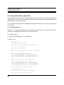
8.1. Using Read Sector and Write Sector to transfer disks . . . . . . . . . . . . . . . . . . . . . . . . . . . .
8.1.1. Read Sector/Write Sector example. . . . . . . . . . . . . . . . . . . . . . . . . . . . . . . . . . . .
8.2. Using PC Transfer to transfer disks (DSKMERGE.EXE) . . . . . . . . . . . . . . . . . . . . . . . . .
8.2.1. PC Transfer example . . . . . . . . . . . . . . . . . . . . . . . . . . . . . . . . . . . . . . . . . . . . . . .
151
151
152
154
154
PC99 User Manual — Stage 6
8.3. Checking a PC99 disk (DSKCHECK.EXE) . . . . . . . . . . . . . . . . . . . . . . . . . . . . . . . . . . . . .
8.4. Cataloging a PC99 disk (DSKDIR.EXE) . . . . . . . . . . . . . . . . . . . . . . . . . . . . . . . . . . . . . . .
8.5. Dumping a PC99 disk (DSKDUMP.EXE) . . . . . . . . . . . . . . . . . . . . . . . . . . . . . . . . . . . . . .
8.6. Finding a TI filename (DSKFIND.EXE) . . . . . . . . . . . . . . . . . . . . . . . . . . . . . . . . . . . . . . .
8.7. Renaming a PC99 disk (DSKNAME.EXE) . . . . . . . . . . . . . . . . . . . . . . . . . . . . . . . . . . . . .
8.8. Extracting a TI file (DSKOUT.EXE) . . . . . . . . . . . . . . . . . . . . . . . . . . . . . . . . . . . . . . . . . .
8.8.1. DSKOUT format. . . . . . . . . . . . . . . . . . . . . . . . . . . . . . . . . . . . . . . . . . . . . . . . . . .
8.8.2. BAS2ASC.EXE . . . . . . . . . . . . . . . . . . . . . . . . . . . . . . . . . . . . . . . . . . . . . . . . . . . .
8.8.3. DV802ASC.EXE . . . . . . . . . . . . . . . . . . . . . . . . . . . . . . . . . . . . . . . . . . . . . . . . . . .
8.8.4. DIS.EXE. . . . . . . . . . . . . . . . . . . . . . . . . . . . . . . . . . . . . . . . . . . . . . . . . . . . . . . . . .
8.8.5. EA5JOIN.EXE. . . . . . . . . . . . . . . . . . . . . . . . . . . . . . . . . . . . . . . . . . . . . . . . . . . . .
8.8.6. EAC2ASC.EXE . . . . . . . . . . . . . . . . . . . . . . . . . . . . . . . . . . . . . . . . . . . . . . . . . . . .
8.8.7. EAU2ASC.EXE . . . . . . . . . . . . . . . . . . . . . . . . . . . . . . . . . . . . . . . . . . . . . . . . . . . .
8.8.8. IV2ASC.EXE. . . . . . . . . . . . . . . . . . . . . . . . . . . . . . . . . . . . . . . . . . . . . . . . . . . . . .
8.8.9. MRG2ASC.EXE. . . . . . . . . . . . . . . . . . . . . . . . . . . . . . . . . . . . . . . . . . . . . . . . . . . .
8.9. Extracting TI Forth screens (DSKOUTF.EXE) . . . . . . . . . . . . . . . . . . . . . . . . . . . . . . . . .
8.10. Extracting p-System files (DSKOUTP.EXE) . . . . . . . . . . . . . . . . . . . . . . . . . . . . . . . . . .
8.10.1. PAS2ASC.EXE . . . . . . . . . . . . . . . . . . . . . . . . . . . . . . . . . . . . . . . . . . . . . . . . . . .
8.11. Importing DOS files to a TI file system (DSKIN.EXE) . . . . . . . . . . . . . . . . . . . . . . . . . .
8.11.1. ASC2DV80.EXE . . . . . . . . . . . . . . . . . . . . . . . . . . . . . . . . . . . . . . . . . . . . . . . . . .
8.11.2. BIN2PGM.EXE . . . . . . . . . . . . . . . . . . . . . . . . . . . . . . . . . . . . . . . . . . . . . . . . . .
8.11.3. DLCONV.EXE . . . . . . . . . . . . . . . . . . . . . . . . . . . . . . . . . . . . . . . . . . . . . . . . . . .
8.11.4. VF2PC99.EXE . . . . . . . . . . . . . . . . . . . . . . . . . . . . . . . . . . . . . . . . . . . . . . . . . . .
8.11.5. VD2PC99.EXE . . . . . . . . . . . . . . . . . . . . . . . . . . . . . . . . . . . . . . . . . . . . . . . . . . .
8.12. Dumping a TI ROM (DUMPROM.EXE) . . . . . . . . . . . . . . . . . . . . . . . . . . . . . . . . . . . . . .
8.13. Patching a TI ROM or GROM (PATCH.EXE) . . . . . . . . . . . . . . . . . . . . . . . . . . . . . . . . .
8.14. Converting Command Modules. . . . . . . . . . . . . . . . . . . . . . . . . . . . . . . . . . . . . . . . . . . . . .
8.14.1. GRAM devices. . . . . . . . . . . . . . . . . . . . . . . . . . . . . . . . . . . . . . . . . . . . . . . . . . . .
8.14.2. Transferring GRAM files. . . . . . . . . . . . . . . . . . . . . . . . . . . . . . . . . . . . . . . . . . .
8.14.3. Conversion example. . . . . . . . . . . . . . . . . . . . . . . . . . . . . . . . . . . . . . . . . . . . . . .
8.15. Speech utilities . . . . . . . . . . . . . . . . . . . . . . . . . . . . . . . . . . . . . . . . . . . . . . . . . . . . . . . . . . .
8.15.1. Displaying the Speech Synthesizer index (SPDUMP.EXE) . . . . . . . . . . . . . .
8.15.2. Displaying Speech Synthesizer codes (SPCODE.EXE) . . . . . . . . . . . . . . . . . .
8.16. Displaying TI-Artist files (ART.EXE) . . . . . . . . . . . . . . . . . . . . . . . . . . . . . . . . . . . . . . . .
8.16.1. Using ART.EXE to create a slide show . . . . . . . . . . . . . . . . . . . . . . . . . . . . . . .
8.17. Using PC99 utilities in batch files . . . . . . . . . . . . . . . . . . . . . . . . . . . . . . . . . . . . . . . . . . .
8.17.1. Bulletin board files . . . . . . . . . . . . . . . . . . . . . . . . . . . . . . . . . . . . . . . . . . . . . . . .
8.17.2. Formatting Basic files . . . . . . . . . . . . . . . . . . . . . . . . . . . . . . . . . . . . . . . . . . . . .
156
157
159
160
162
163
163
164
164
165
167
167
167
168
168
169
170
170
170
171
172
173
174
175
176
177
178
178
178
179
183
183
183
185
187
188
188
189
9. PC99.DSK utility programs . . . . . . . . . . . . . . . . . . . . . . . . . . . . . . . . . . . . . . . . . . . . . . . . . . . . . . . . . .
9.1. ARC33_1 . . . . . . . . . . . . . . . . . . . . . . . . . . . . . . . . . . . . . . . . . . . . . . . . . . . . . . . . . . . . . . . . .
9.2. ASSM1, ASSM2 . . . . . . . . . . . . . . . . . . . . . . . . . . . . . . . . . . . . . . . . . . . . . . . . . . . . . . . . . . . .
9.3. BSCSUP . . . . . . . . . . . . . . . . . . . . . . . . . . . . . . . . . . . . . . . . . . . . . . . . . . . . . . . . . . . . . . . . . .
9.4. DEBUG . . . . . . . . . . . . . . . . . . . . . . . . . . . . . . . . . . . . . . . . . . . . . . . . . . . . . . . . . . . . . . . . . .
190
191
191
191
191
TEXAS INSTRUMENTS
HOME COMPUTER
9.5. DM, DM1, DM2 . . . . . . . . . . . . . . . . . . . . . . . . . . . . . . . . . . . . . . . . . . . . . . . . . . . . . . . . . . . .
9.6. EDIT1 . . . . . . . . . . . . . . . . . . . . . . . . . . . . . . . . . . . . . . . . . . . . . . . . . . . . . . . . . . . . . . . . . . . .
9.7. FILETOPROG . . . . . . . . . . . . . . . . . . . . . . . . . . . . . . . . . . . . . . . . . . . . . . . . . . . . . . . . . . . .
9.8. RSECTOR, RSECT_O, SECTLOAD_X, WSECTOR, WSECT_O . . . . . . . . . . . . . . . . . . .
9.9. MMLOAD_M, MMSAVE_M . . . . . . . . . . . . . . . . . . . . . . . . . . . . . . . . . . . . . . . . . . . . . . . . .
9.9.1. Loading large TI Basic programs . . . . . . . . . . . . . . . . . . . . . . . . . . . . . . . . . . . . .
9.10. XLATE_X . . . . . . . . . . . . . . . . . . . . . . . . . . . . . . . . . . . . . . . . . . . . . . . . . . . . . . . . . . . . . . . .
191
192
192
192
192
193
194
10. PC99 patches . . . . . . . . . . . . . . . . . . . . . . . . . . . . . . . . . . . . . . . . . . . . . . . . . . . . . . . . . . . . . . . . . . . . .
10.1. Console ROM 0: Speeding up the keyboard . . . . . . . . . . . . . . . . . . . . . . . . . . . . . . . . . . . .
10.2. Console ROM 0: Bug in interrupt routine . . . . . . . . . . . . . . . . . . . . . . . . . . . . . . . . . . . . .
10.3. Console GROM 0: Bug in REVIEW MODULE LIBRARY . . . . . . . . . . . . . . . . . . . . . . . .
10.4. RS232 card ROM: Reducing timeout . . . . . . . . . . . . . . . . . . . . . . . . . . . . . . . . . . . . . . . . .
195
195
195
196
196
11. In case of difficulty. . . . . . . . . . . . . . . . . . . . . . . . . . . . . . . . . . . . . . . . . . . . . . . . . . . . . . . . . . . . . . . . .
11.1. Can't execute PC99.EXE . . . . . . . . . . . . . . . . . . . . . . . . . . . . . . . . . . . . . . . . . . . . . . . . . . .
11.1.1. PMINFO.EXE . . . . . . . . . . . . . . . . . . . . . . . . . . . . . . . . . . . . . . . . . . . . . . . . . . .
11.2. Can't execute PC99.EXE . . . . . . . . . . . . . . . . . . . . . . . . . . . . . . . . . . . . . . . . . . . . . . . . . . .
11.3. Not enough memory to run PC99 . . . . . . . . . . . . . . . . . . . . . . . . . . . . . . . . . . . . . . . . . . . .
11.4. Can't open COMn . . . . . . . . . . . . . . . . . . . . . . . . . . . . . . . . . . . . . . . . . . . . . . . . . . . . . . . . .
11.5. Can't open DSKn . . . . . . . . . . . . . . . . . . . . . . . . . . . . . . . . . . . . . . . . . . . . . . . . . . . . . . . . . .
11.6. Can't open <filename> . . . . . . . . . . . . . . . . . . . . . . . . . . . . . . . . . . . . . . . . . . . . . . . . . . . .
11.7. Error messages corrupt display . . . . . . . . . . . . . . . . . . . . . . . . . . . . . . . . . . . . . . . . . . . . .
11.8. COM port problems . . . . . . . . . . . . . . . . . . . . . . . . . . . . . . . . . . . . . . . . . . . . . . . . . . . . . . .
11.9. Printer problems . . . . . . . . . . . . . . . . . . . . . . . . . . . . . . . . . . . . . . . . . . . . . . . . . . . . . . . . . .
11.10. Known problems . . . . . . . . . . . . . . . . . . . . . . . . . . . . . . . . . . . . . . . . . . . . . . . . . . . . . . . . .
197
197
197
199
199
203
203
203
203
203
204
204
12. Limited Warranty . . . . . . . . . . . . . . . . . . . . . . . . . . . . . . . . . . . . . . . . . . . . . . . . . . . . . . . . . . . . . . . . .
12.1. Three-month limited warranty — PC99 Software Media . . . . . . . . . . . . . . . . . . . . . . . .
12.2. Warranty duration . . . . . . . . . . . . . . . . . . . . . . . . . . . . . . . . . . . . . . . . . . . . . . . . . . . . . . . .
12.3. Performance by CaDD Electronics under warranty . . . . . . . . . . . . . . . . . . . . . . . . . . . . .
12.4. CaDD Electronics Consumer Service Facility . . . . . . . . . . . . . . . . . . . . . . . . . . . . . . . . . .
12.5. Important notice of disclaimer regarding the programs . . . . . . . . . . . . . . . . . . . . . . . . .
205
205
205
205
205
205
PC99 User Manual — Stage 6
1. Quick start
This section is for people who hate to read documentation. It contains enough information to get you up
and running. However, to get the full benefit of the PC99 product, you should at least try to glance
through the remainder of the documentation, especially the section on peripherals, and topics such as TI
vs. Myarc disk controller. If you are new to using the Myarc Disk Manager, you should read the document:
Myarc Disk Manager Level III Supreme. This is contained in the file MYDMDOC.PDF (Adobe Portable
Document Format) or MYDMDOC.TXT (ASCII format).
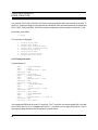
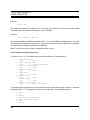
1.1. Installation
Insert the PC99 distribution disk 1 in your PC floppy drive. The following example assumes you are
installing from the A: floppy drive to the C: hard drive. At the DOS prompt:
> a:
> install1 a c
[Note: install{one}, not {el}]
INSTALL1.EXE builds a directory tree under \PC99 on the C: drive and expands compressed files into
it.
Insert the PC99 distribution disk 2 in the A: drive. At the DOS prompt:
> install2 a c
INSTALL2.EXE expands compressed files into \PC99.
Insert the PC99 distribution disk 3 in the A: drive. At the DOS prompt:
> install3 a c
INSTALL3.EXE expands compressed files into \PC99.
1
TEXAS INSTRUMENTS
HOME COMPUTER
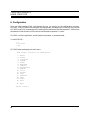
1.2. Configuration
You must configure PC99 to match your PC hardware, and your personal preferences. You do this by
running the PC99 configuration program, CFG.EXE. CFG.EXE is menu-driven and almost every screen
has context-sensitive help.
To configure PC99:
> c:
> cd \pc99
> cfg
Select the section you wish to configure. To get help press <F1>.
One of the main uses of CFG.EXE is to change command modules. Your list of command modules and
their associated filenames are in the ASCII file PC99.MOD.
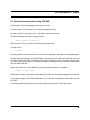
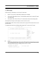
1.3. 99/4A emulator
PC99 is the TI-99/4A emulator program. There are two products:
PC99 Stage 6 Full.
Includes PC99.EXE (standard version), PC99A.EXE (accelerated version), all required ROM and
GROM files, and a range of utility programs.
PC99 Stage 6 Light.
Includes PC99L.EXE (light version), all required ROM and GROM files, and a range of utility
programs.
Note: Unless dealing specifically with a particular version, all examples will show PC99.EXE. You should
substitute PC99.EXE, PC99A.EXE or PC99L.EXE where applicable.
To load PC99 from the DOS prompt:
> c:
> cd \pc99
> pc99
To quit PC99, press <Esc>. The current debugger screen is displayed. Press <Q> (upper case q) to
return to DOS.
2
PC99 User Manual — Stage 6
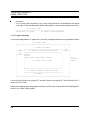
2. Introduction
PC99 is a DOS protected-mode program that runs on a 386 or higher IBM PC or compatible and emulates
the Texas Instruments TI-99/4A Home Computer and selected peripherals.
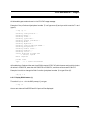
2.1. Features
The table below lists TI-99/4A console and peripheral features and how they are emulated in PC99:
TI-99/4A
PC99
TMS9900
16-bit processor
Fully emulated. All 69 instructions and all corresponding addressing
modes are implemented.
TMS9918A
Video Display Processor
Memory: Fully emulated. Up to 16K VDP memory can be addressed.
Address wrap from >3FFF to >0000 is emulated.
Write-only registers: Fully emulated. All eight registers can be
addressed.
Display modes: Fully emulated. All four standard modes (graphics,
bitmap, text and multicolor) are available. In addition, the
undocumented "half bitmap" mode can be used.
Colors: Fully emulated in PC VGA mode 19 with PC color monitor.
Any pixels that are on in a group of 8 may be one of 16 colors. Any
pixels that are off in the same group can be one of 16 colors.
Sprites: Fully emulated. Up to 32 sprites can be defined.
TMS9901 Programmable
Systems Interface
All of the features used on the 99/4A are fully emulated.
TMS9919
Sound Processor
Standard PC: Partially emulated. On the 99/4A the TMS9919 chip
has three sound channels (1, 2 and 3) and one noise channel. A
standard PC has only one sound channel. PC99 only emulates TI
sound channel 1. This is a PC limitation.
PC with Sound Blaster: Fully emulated. The three TI sound
channels are played on Sound Blaster channels 1, 2, and 3. The
maximum frequency is 16,384Hz. This is a Sound Blaster limitation.
The TI noise channel is played on Sound Blaster channels 7, 8 and 9.
3
TEXAS INSTRUMENTS
HOME COMPUTER
TI-99/4A
PC99
TI console joystick port
Standard PC: Fully emulated using PC ALT function keys (<F1> <F10>).
PC with game port: Fully emulated. Depending on the hardware,
up to two PC joysticks can be connected to the game port. The PC
joysticks are used to emulate the actions of TI joysticks.
4
TI console cassette port
Partially emulated. A "SAVE CS1" creates a DOS disk file. You
cannot load this file with "OLD CS1". You cannot save or load to CS2.
TI console
command module port
In PC99 a TI "command module" consists of one or more DOS files.
These are loaded into PC memory. You "change a command module"
by running the PC99 configuration utility (CFG.EXE). Almost all
TI-manufactured command modules are fully emulated under PC99.
The same applies to third party command modules. No "lockups" due
to bad contacts can occur.
TI command module
bank switching
TI, DataBioTics, MBX, and Mechatronics bank switching schemes
are fully emulated. Some command modules, such as TI Extended
Basic and TI Calc, or DataBioTics TI Workshop, use this feature.
MBX command modules which do not require the MBX console are
fully emulated in PC99.
TI GROMs
The TI GROM memory map, auto-incrementing actions of a GROM,
and GROM memory wrap are fully emulated. Up to 16 banks, each
containing 5 8K GROMs, can be loaded. Multiple GROM banks are
emulated using the REVIEW MODULE LIBRARY feature in the TI
console.
TI console keyboard
Almost every key and shift mode (SHIFT, CTRL, FCTN) on the 99/4A
keyboard can be keyed on the PC keyboard. PC99 does not support
TI multiple shift modes (for example, FCTN SHIFT B).
TI memory map
PC99 fully emulates the TI memory map:
>0000->1FFF 8K console ROM
>2000->3FFF 8K low memory expansion
>4000->5FFF 8K peripheral ROMs
>6000->7FFF 8K ROMs in cmd modules
>8000->9FFF 8K memory-mapped
>A000->FFFF 24K high memory
TI 32K
memory expansion card
Fully emulated. This peripheral contains 8K of low memory and 24K
of high memory. All of this memory is treated as if it were on the TI
fast 16-bit bus.
PC99 User Manual — Stage 6
TI-99/4A
PC99
Myarc 512K
memory expansion card
Fully emulated. This peripheral contains 32K of memory which is
used as standard TI 32K memory expansion. The rest of the memory
can be partitioned into a 128K space for Myarc XB II, and a RAM
disk and print spooler.
AMS memory card
Fully emulated. You can select whether to emulate the 128K, 256K,
512K or 1Mb version of the card depending on how much PC
memory you have available.
Super Space II
Fully emulated. 4 8K banks of Super Space RAM can be enabled at
>6000->7FFF. Up to 16 of these 32K banks can be enabled.
TI disk controller card
Fully emulated. The TI disk controller supports up to three drives.
Each disk can contain 720 256-byte sectors (DSSD). PC99 uses three
DOS disk files to represent the three drives.
Guion disk controller
Fully emulated. John Guion supplied an 8K ROM for the TI disk
controller and a hardware kit. After installation the controller can
access four drives. Each disk can contain 720 256-byte sectors
(DSSD). PC99 uses four DOS disk files to represent the four drives.
Myarc disk controller card
Fully emulated. The Myarc disk controller supports up to four
drives. Each disk can contain 1440 256-byte sectors (DSDD). PC99
uses four DOS disk files to represent the four drives.
TI RS232 primary card
TI RS232 secondary card
Fully emulated, if the PC has up to two COM ports and one parallel
port. The TI ports are: RS232, RS232/1, RS232/2, PIO, and PIO/1.
(Note: RS232 and RS232/1, and PIO and PIO/1 are the same ports.)
PC99 can exchange data at up to 9,600 bps over the PC COMn ports,
and can drive a TI compatible printer connected to the PC LPTn
port.
Guion RS232 card
Fully emulated. John Guion supplied an 8K ROM for the TI RS232
card. This allowed devices such as TP to be used and have the output
sent to standard devices, such as RS232.
PC99 "card"
This is a software only "card", and was not an original TI or thirdparty peripheral. This "card" contains a DSR for the support of a
real-time clock which emulates the CorComp Triple-Tech clock. You
can also create your own DSRs for this "card".
TI p-Code card
Fully emulated. You can use CFG.EXE to enable the p-Code card,
which consists of a bank-switched 8K ROM and 8 6K GROMs.
5
TEXAS INSTRUMENTS
HOME COMPUTER
TI-99/4A
PC99
TI Speech Synthesizer
Partially emulated. All of the software functions of the TMS5200 are
fully emulated, but no audible speech is generated. This allows you to
run programs that require the Speech Synthesizer.
2.2. Additional features
PC99 includes additional features that are not available on a TI-99/4A:
2.2.1. PC99 debugger
The PC99 debugger displays a TI "Mini-Screen" surrounded by editable objects which allow you to control
every aspect of PC99. With the debugger, you can stop any TI application at any time, including during
disk access. You can single-step through any TI application, set breakpoints and watchpoints, examine
and change any TI addressable memory (CPU, GROM, VDP, and command module space), and read and
write the VDP write-only registers. You can also display any sprites being used, including their patterns
and locations.
Using the powerful features of the debugger you can debug assembly language programs, examine the
workings of the GPL interpreter, and find out how a peripheral device service routine (DSR) works.
Because the PC99 debugger does not use any TI memory, you can debug any TI application, no matter
how large. No TI debugger running on a standard 4A can do this.
6
PC99 User Manual — Stage 6
2.2.2. PC99 utilities
PC99 includes the following utilities:
ART.EXE: allows you to display TI-Artist files in DOS.
CFG.EXE: allows you to configure PC99.
CFGGEN.EXE: allows you to generate a clean configuration file.
DUMP.EXE: allows you to dump a DOS file in hex and ASCII.
DUMPROM.EXE: allows you dump a TI ROM in hex to an ASCII file.
GREAD.EXE: allows you to strip unwanted trailers off files.
GSTRIP.EXE: allows you to strip unwanted headers off files.
PATCH.EXE: allows you to make patches to ROMs and GROMs.
2.2.3. PC99 disk utilities
PC99 includes the following disk utilities:
DSKCHECK.EXE: allows you check the integrity of a TI "disk".
DSKDIR.EXE: allows you to catalog a TI "disk" from DOS.
DSKDUMP.EXE: allows you to dump the data of a TI "disk".
DSKFIND.EXE: finds a disk manager filename using a wildcard selection of disk files.
DSKIN.EXE: allows you to take a DOS file and store it in a TI "disk".
DSKMERGE.EXE: allows you to merge files transferred from a 99/4A system into a TI "disk".
DSKNAME.EXE: allows you to rename a TI "disk" from DOS.
DSKOUT.EXE: allows you to extract a file from a TI "disk" and store it as a standalone DOS file.
DSKOUTF.EXE: allows you to extract Forth screens from a TI Forth "disk" and store them as a
DOS file.
DSKOUTP.EXE: allows you to extract a file from a TI p-System "disk" and store it as a DOS file.
7
TEXAS INSTRUMENTS
HOME COMPUTER
The following utilities are used on files extracted by DSKOUT.EXE:
BAS2ASC.EXE: converts TI Basic or Extended Basic program files into ASCII. The converted file
can be loaded into PC Basic. [Not all TI Basic statements are valid in PC Basic.]
BASFMT.EXE: converts extracted TI Basic or Extended Basic files and formats them to match
a program listing on the 28-column TI screen.
DIS.EXE: disassembles single E/A5 files and E/A5 files that have been "joined" by EA5JOIN.EXE.
DV802ASC.EXE: converts TI Display/Variable 80 files into ASCII. The converted file can be
loaded into a PC word processor, such as WordPerfect.
EA5JOIN.EXE: loads successive E/A5 files into an equivalent TI memory space and saves as a
single file. The output file can be used by the PC99 disassembler, DIS.EXE.
EAC2ASC.EXE: converts E/A3 compressed format files to ASCII. Shows all tags by name, the load
offset, and contents in hex and ASCII.
EAU2ASC.EXE: converts E/A3 uncompressed format files to ASCII. Shows all tags by name, the
load offset, and contents in hex and ASCII.
IV2ASC.EXE: converts TI Extended Basic INT/VAR 254 program files into ASCII. The converted
file can be loaded into PC Basic. [Not all TI Extended Basic statements are valid in PC Basic.]
MRG2ASC.EXE: converts TI Basic or Extended Basic files saved in INT/VAR 163 (MERGE)
format into ASCII. The converted file can be loaded into PC Basic. [Not all TI Basic statements
are valid in PC Basic.]
The following utilities are used with DSKOUTP.EXE:
8
PAS2ASC.EXE: converts TI p-System .TEXT files into ASCII.
PC99 User Manual — Stage 6
The following utilities are used with DSKIN.EXE:
ASC2DV80.EXE: takes a DOS ASCII file and converts it to TI-Writer format. This file can be
stored in a TI "disk" using DSKIN.EXE.
BIN2PGM.EXE: takes a DOS binary file containing a TI Basic or Extended Basic PROGRAM file,
typically downloaded from a bulletin board, and converts it to a file. This file can be stored in a
TI "disk" using DSKIN.EXE.
DLCONV.EXE: takes a DOS binary file containing a "TI FILES" header, typically downloaded
from a bulletin board, and converts it to a file. This file can be stored in a TI "disk" using
DSKIN.EXE.
VF2PC99.EXE: takes a single v9t9 "file in a directory" and converts it to PC99 format.
VD2PC99.EXE: takes a v9t9 "disk on a disk" and converts it to PC99 format.
9
TEXAS INSTRUMENTS
HOME COMPUTER
2.3. Features available by product
There are two PC99 products depending on the package you purchased:
PC99 Stage 6 Full.
Includes PC99.EXE (standard version), PC99A.EXE (accelerated version), all required ROM and
GROM files, and a range of utility programs.
PC99 Stage 6 Light.
Includes PC99L.EXE (light version), all required ROM and GROM files, and a range of utility
programs.
All of the features described above are available in each product, with the following exceptions:
p-Code
Multiple GROMs
Mini-Screen debugger
---------------- Full --------------PC99.EXE
PC99A.EXE
Yes
Yes
Yes
Yes
Yes
No
Light
PC99L.EXE
No
No
No
PC99 Stage 6 Full comes with both PC99.EXE and PC99A.EXE. PC99A.EXE offers accelerated
performance. This performance increase comes from eliminating the Mini-Screen debugger. You should
run whichever version is most suitable for your needs.
The Full product is the equivalent of:
1.
A TI-99/4A console with choice of TI-99/4A, TI-99/4A version 2.2, CDC, or OPA ROMs and
GROMs and support for up to 16 GROM-based command modules.
2.
A Peripheral Expansion Box containing a TI 32K or Myarc 512K or AMS memory card; TI,
Guion, or Myarc Disk Controller; TI, or Guion RS232 card; TI p-Code card; and PC99 "card"
(real-time clock).
3.
A TI Speech Synthesizer (speech functions work, no audible speech is produced).
4.
TI Extended Basic, TI Editor/Assembler, Tombstone City, and Mechatronic Extended Basic II
Plus command modules. In addition, you have access to the PC99 Mini-Screen debugger.
PC99 Stage 6 Light comes with PC99L.EXE only. You cannot run the p-Code card, multiple GROMs or
the Mini-Screen debugger. The performance is the same as PC99A.EXE.
Note: Unless dealing specifically with a particular version, all examples in this document will show
PC99.EXE. You should substitute PC99.EXE, PC99A.EXE or PC99L.EXE where applicable.
10
PC99 User Manual — Stage 6
2.4. Hardware requirements
The PC must have the following hardware:
80386 or higher microprocessor (80486 at 66MHz is minimum recommended; Pentium, Pentium
II is supported).
At least 16Mb RAM.
Color VGA adapter and monitor.
Disk drive to load software: 3.5" 1.44Mb.
A hard drive with at least 10Mb free.
Optional PC hardware includes:
ISA bus: Up to four COM ports based at PC I/O addresses 0x2f8, 0x3f8, 0x2e8 and 0x3e8 to
emulate the TI RS232 ports.
MicroChannel Architecture: Up to eight COM ports based at PC I/O addresses 0x2f8, 0x3f8,
0x3220, 0x3228, 0x3320, 0x3328, 0x3420 and 0x3428.
A parallel port to emulate the TI PIO port.
A game port and one or two PC analog joysticks to emulate the TI "digital" joystick port.
A Creative Labs Sound Blaster for improved sound reproduction.
2.5. Software requirements
The PC must have the following software:
DOS 5.0, DOS 6.0, DOS 6.2 (or later). Earlier versions of DOS down to 3.3 will probably work. We
do not recommended running PC99 from a DOS shell or from a DOS box under Microsoft
Windows 3.1 or Microsoft Windows for Workgroups 3.11.
or
Microsoft Windows 95/98. PC99 will execute in a DOS box.
Your PC environment must allow PC99 to switch the processor from real mode to protected mode. Some
anti-virus programs may prevent this.
11
TEXAS INSTRUMENTS
HOME COMPUTER
2.6. Terminology
2.6.1. Keystrokes
PC keystrokes are shown as <keyname>. For example, <Esc> is the PC Escape key, <Tab> is the PC
Tab key, <Ctrl-X> is the PC <Ctrl> key and the <X> key pressed together, and <Shift-Q> is the PC
<Shift> and the <Q> key pressed together.
These are distinguished from equivalent TI keys. For example, CTRL is the TI CTRL key, and FCTN is
the TI FCTN key.
2.6.2. Hexadecimal values
When referring to hexadecimal (hex) 16-bit values in the TI world, the TI convention of >NNNN is used.
In the PC world the convention 0xNNNN is used. Similarly 8-bit values are >NN and 0xNN respectively.
Example: >2000 is 2000 hex or 8192 decimal.
Example: 0xFF is FF hex or 255 decimal.
2.6.3. DOS commands
When examples of DOS commands are given, the use of the <Enter> key is assumed. The DOS prompt
is shown as >.
Example: > cd \pc99
This means that at the DOS prompt (>), type the "cd" command (change directory) followed by "\pc99"
and press <Enter>. This will place you in the "pc99" directory, which lives immediately below the root
"\" directory.
Note: Most PC users enable the DOS PROMPT function, so that the actual prompt includes the current
directory.
Example: C:\PC99>
Note: DOS commands are case insensitive.
12
PC99 User Manual — Stage 6
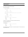
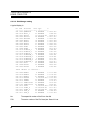
2.6.4. Disk Densities
The following table shows the relationship between TI 5.25" diskettes in terms of: disk sides, density, and
number of sectors; together with the corresponding mnemonic and description. Most examples in this
manual use the mnemonic form.
No. of
sides
1
2
2
Density
1
1
2
Sectors
360
720
1440
Mnemonic
SSSD
DSSD
DSDD
Description
single-sided single-density
double-sided single-density
double-sided double-density
2.6.5. Fast PC
When reference is made to a "fast PC", we mean a PC that has the typical performance of a 90MHz
Pentium, or better.
2.6.6. ASCII editor
When reference is made to an "ASCII editor", we mean an editor such as Solution Systems' Brief, or DOS's
EDIT. You typically use such an editor to edit files like AUTOEXEC.BAT or CONFIG.SYS.
2.6.7. Protected mode
The Intel 8088 processor used in the original IBM PC had only one mode of operation. It came to be called
real mode. The 8088 processor can address 1Mb of memory. IBM reserved the upper 384K of the 1Mb
address space for such things as video memory, and the ROM BIOS. This left a maximum of 640K for DOS
applications — the so-called 640K barrier.
Intel's later processors (80286, 80386, 80486 and Pentium) allow for a second operating mode, called
protected mode. Perhaps the most important aspect of protected mode is that the processor can address
much more memory. When running in protected mode, the 16-bit 80286 processor can address 16Mb of
memory, while the 32-bit 80386 and later processors can address 4Gb.
DOS is inherently a real mode operating system. Because of this, DOS applications running on an 80286
and later processors are still restricted to the 640K barrier. Therefore, these systems function merely as
faster 8088 systems.
Some attempts to improve this limitation included using expanded and extended memory services to
provide limited access to this larger address space. However, if a program wants to treat the memory
above 1Mb like conventional DOS memory, it must run in protected mode.
When neither Microsoft nor IBM introduced a DOS-compatible protected mode operating system, DOS
extenders were developed by third party companies. A DOS extender is a mini operating system, that can
run protected mode applications under DOS.
13
TEXAS INSTRUMENTS
HOME COMPUTER
The DOS extender accomplishes this by executing a real mode stub program that switches the processor
to protected mode and passes control to a calling program. PC99 is such a calling program. PC99 runs in
protected mode until it requests a DOS service, such as file I/O. The DOS extender then switches back to
real mode to satisfy the request, and when done reverts to protected mode.
When PC99 terminates, the DOS extender switches back to real mode and returns control to DOS. These
behind-the-scenes tasks are transparent to you.
PC99 uses the DOS/4GW 32-bit extender written by Rational Systems (later Tenberry Software) and
supplied with the Watcom C compiler. PC99 therefore requires an 80386 or later processor to run. It will
not run on an 80286.
The DOS/4GW extender will identify itself with:
DOS/4GW Protected Mode Run-Time Version n.nn
copyright (c) Rational Systems, Inc 1990-94
You can suppress this header by setting an environment variable:
SET DOS4G=quiet
You can do this at the DOS prompt, or in your AUTOEXEC.BAT file.
14
PC99 User Manual — Stage 6
3. Documentation
The PC99 documentation set consists of:
PC99 User Manual (this document)
\pc99\doc\pd99doc.pdf in Acrobat format.
\pc99\doc\pc99doc.txt in text format. Can be read with an ASCII editor.
How to install, configure, and use all features of PC99.
Mechatronic Extended Basic II Plus
\pc99\doc\mechaxb.pdf in Acrobat format.
How to use the Mechatronic Extended Basic II Plus command module features under PC99.
Myarc 512K Memory Expansion Card
\pc99\doc\myarc512.pdf in Acrobat format.
How to use the Myarc 512K Memory Expansion card under PC99 and the use of the CALL PART
instruction.
Myarc Disk Manager Level III Supreme
\pc99\doc\mydmdoc.pdf in Acrobat format.
How to use Myarc's Disk Manager Level III Supreme software under PC99. Includes screen snaps
that were not part of the original manual. This software is supplied on \pc99\dsk\pc99.dsk and is
invoked through E/A 3 with DSK1.DM.
Myarc XB Basic II version 2.12.
\pc99\doc\myxbdoc.pdf in Acrobat format.
How to use Myarc Extended Basic II version 2.12. PC99 must be configured with the Myarc 512K
card and the XBII option to use this language.
Introduction to the p-System
\pc99\doc\pasdoc.pdf in Acrobat format.
\pc99\doc\pasdoc.txt in text format. Can be read with an ASCII editor.
An introduction to using the UCSD p-System under PC99. The p-Code peripheral must be
enabled to use the p-System.
15
TEXAS INSTRUMENTS
HOME COMPUTER
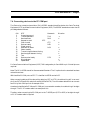
4. Supplied software
The software supplied in your PC99 package can be divided into five categories:
1. Installation
2. Configuration
3. 99/4A Emulator
4. Utilities
5. PC99.DSK Utilities
INSTALL1.EXE, INSTALL2.EXE, INSTALL3.EXE
CFG.EXE
PC99.EXE, PC99A.EXE (PC99L.EXE)
About 30 separate programs
TI utility programs
Installing PC99 is usually a one-shot process. PC99 is supplied on three diskettes, each with their own
install program. Once you have run INSTALL1.EXE, INSTALL2.EXE and INSTALL3.EXE and
completed the installation there is usually no need to run the install programs again.
After installation, you should configure PC99 to match your PC hardware, and your preferences. You do
this by running CFG.EXE.
After that, you only need to run CFG.EXE when you want to change your PC99 configuration; for
example, if you need to change a command module, switch a peripheral, or enable the speech synthesizer.
For everyday use you will run PC99.EXE.
Occasionally you will need to run one of the many supplied utilities.
The following sections of this document cover the five categories above in the order shown.
16
PC99 User Manual — Stage 6
5. Installation
Note: If you have a previous version of PC99 you should back up all existing files before starting install.
One way to do this is:
>
>
>
>
>
c:
cd \
mkdir \pc99bak
xcopy \pc99\*.* \pc99bak /s /e /v
deltree \pc99
This creates a \pc99bak directory, copies all files and sub-directories in the \pc99 directory to \pc99bak,
and then removes the \pc99 directory. In the xcopy command,
/s means copy sub-directories,
/e means copy empty files, and
/v means verify the copy.
In later versions of DOS you can simply move the directory:
> c:
> cd \
> move pc99 pc99bak
PC99 is supplied on three disks, numbered 1, 2 and 3. Each has its own install program: INSTALL1.EXE,
INSTALL2.EXE, and INSTALL3.EXE respectively. You must install disk 1 first, then disk 2, and then
disk 3.
For each install program, the syntax is:
install{1-3} <source drive {A-Z}> <target drive {A-Z}>
where
install{1-3} is INSTALL1.EXE if you are installing disk 1, INSTALL2.EXE if you are installing
disk 2, and INSTALL3.EXE if you are installing disk 3.
<source drive {A-Z}> is the letter of the floppy drive (no colon) you will install from. Example:
A.
<target drive {A-Z}> is the letter of the hard drive (no colon) you will install to. Example: C.
17
TEXAS INSTRUMENTS
HOME COMPUTER
Example: To install PC99 from the A: floppy drive to the C: hard drive, insert the PC99 distribution disk
1 in drive A. At the DOS prompt:
> a:
> cd \
> install1 a c
Remove distribution disk 1 and insert distribution disk 2:
> install2 a c
Remove distribution disk 2 and insert distribution disk 3:
> install3 a c
Please note that you should not execute any of the .EXE files on the distribution disks — except for
INSTALL1.EXE, INSTALL2.EXE, and INSTALL3.EXE. The other .EXE files are self-extracting
compressed files used by the installation programs.
5.1. PC99 tree
After a successful install, you should have the following files in the PC99 tree. The listings are in DOS sort
order.
(F) = full-featured product only
(L) = light product only
\PC99
CFG.EXE
CFG.MNU
CFGPLATO.MNU
CFGSB.EXE
DOS4GW.EXE
PC99.CFG
(F)
PC99.EXE
PC99.FGF
PC99.MMM
PC99.MOD
18
The PC99 configuration program.
An ASCII file that contains the menus used by CFG.EXE.
An ASCII file that contains the menus used by CFG.EXE when selecting
Plato disks.
A 16-bit program used by CFG.EXE to check for the existence of a
Creative Labs Sound Blaster.
The Rational Systems DOS/4GW DOS extender that enables PC99.EXE
to run in 32-bit protected mode.
An ASCII file that contains PC99 configuration information. CFG.EXE
reads and writes this file. PC99.EXE reads this file.
The 99/4A emulator program (standard version).
A font file containing bitmaps of characters used when displaying module
overlay files.
An editable ASCII file that contains a master list of modules. You can cut
and paste from this file to PC99.MOD when you acquire new modules.
An editable ASCII file that contains your list of modules. CFG.EXE reads
this file.
PC99 User Manual — Stage 6
(F)
(L)
PC994A.KEY
PC99A.EXE
PC99L.EXE
Keyboard file for emulating a 99/4A. PC99.EXE reads this file.
The 99/4A emulator program (accelerated version).
The 99/4A emulator program (light version).
\PC99\DOC
MECHAXB.PDF
(F)
(F)
Mechatronic Extended Basic II Plus command module documentation in
Adobe Acrobat pdf format.
MYARC512.PDF
Myarc's 512K Memory Expansion card documentation in Adobe Acrobat
pdf format.
MYDMDOC.PDF
Myarc's Disk Manager Level III Supreme documentation in Adobe
Acrobat pdf format..
MYXBDOC.PDF
Myarc Extended Basic II version 2.12 documentation in Adobe Acrobat
pdf format.
PASDOC.PDF
An introduction to using the p-System under PC99 in Adobe Acrobat pdf
format.
PASDOC.TXT
An introduction to using the p-System under PC99 in ASCII format.
PC99DOC.PDFPC99 documentation in Adobe Acrobat pdf format.
PC99DOC.TXTPC99 documentation in ASCII format. Can be read with DOS's EDIT.
README.TXT An ASCII file that explains how to get to the PC99 documentation.
\PC99\DSK
CS1
CS2
DSK1
DSK2
DSK3
DSK4
FMT21.DSK
FMT22.DSK
MECHAXB.DSK
PC99.DSK
(F)
PFMT21.DSK
(F)
PFMT22.DSK
A dummy file representing a TI cassette.
A dummy file representing a TI cassette.
A copy of FMT21.DSK.
A copy of FMT21.DSK.
A copy of FMT21.DSK.
A copy of FMT21.DSK.
A file representing a blank TI DSSD disk.
A file representing a blank TI DSDD disk.
A file representing a TI DSSD disk containing examples from the
Mechatronic Extended Basic II Plus manual.
A TI "disk" containing PC99 utilities that allow you to transfer disks to
and from a 4A, and other programs.
A file representing a blank TI DSSD disk that has been Z(ero'ed for use
with the p-System.
A file representing a blank TI DSDD disk that has been Z(ero'ed for use
with the p-System.
\PC99\DSKUTIL
ASC2DV80.EXE
A program that takes a DOS ASCII file and converts it to TI-Writer
format. This file can be stored in a TI "disk" using DSKIN.EXE.
BAS2ASC.EXE A program that takes a TI Basic or Extended Basic PROGRAM file extracted by
DSKOUT.EXE and converts it to ASCII.
19
TEXAS INSTRUMENTS
HOME COMPUTER
BASFMT.EXE
A program that takes an extracted TI Basic or Extended Basic file and
formats it to match the listing on a 28-column TI screen.
BIN2PGM.EXE
A program that takes a DOS binary file containing a TI Basic or TI
Extended Basic PROGRAM file and extracts it to a file. This file can be
stored in a TI "disk" using DSKIN.EXE.
DIS.CTL
A default minimal control file used by DIS.EXE.
DIS.EXE
A program that takes an E/A5 file extracted by DSKOUT.EXE, or E/A5
files that have been extracted by DSKOUT.EXE and "joined" by
EA5JOIN.EXE, and disassembles them.
DLCONV.EXE
A program that takes a DOS binary file containing a "TI FILES" header
and converts it to a file. This file can be stored in a TI "disk" using
DSKIN.EXE.
DSKCHECK.EXE
A program that checks the integrity of a TI "disk".
DSKDIR.EXE
A program that catalogs a TI "disk" from DOS.
DSKDUMP.EXE
A program that dumps the data of a TI "disk" to a DOS file.
DSKFIND.EXE
A program that finds a disk manager filename using a wildcard selection
of disk files.
DSKIN.EXE
A program that takes a DOS file and stores it as a TI file on a TI "disk".
DSKMERGE.EXE
A program that merges PC-Transfer files into a TI "disk".
DSKNAME.EXE
A program that renames a TI "disk" from DOS.
DSKOUT.EXE
A program that extracts a TI file from a TI "disk" and stores it as a DOS
binary file.
DSKOUTF.EXE
A program that extracts TI Forth screens from a TI Forth "disk" and
stores them as a DOS ASCII file.
DSKOUTP.EXE
A program that extracts a file from a TI p-System "disk" and stores it as
a DOS file.
DV802ASC.EXE
A program that takes a DIS/VAR 80 file extracted by DSKOUT.EXE and
converts it to ASCII.
EA5JOIN.EXE A program that loads successive E/A5 files into an equivalent TI memory space
and saves as a single file. The E/A5 files are extracted with DSKOUT. The single
file is used by DIS.EXE.
EAC2ASC.EXEA program that takes an E/A3 compressed format file extracted by DSKOUT.EXE
and converts it to ASCII.
EAU2ASC.EXE
A program that takes an E/A3 uncompressed format file extracted by
DSKOUT.EXE and converts it to ASCII.
IV2ASC.EXE
A program that takes a TI Extended Basic INT/VAR254 file extracted by
DSKOUT.EXE and converts it to ASCII.
MRG2ASC.EXE
A program that takes a TI Basic or Extended Basic INT/VAR163 file
saved in Merge format and extracted by DSKOUT.EXE and converts it
to ASCII.
PAS2ASC.EXE A program that converts TI p-System .TEXT files into ASCII.
VF2PC99.EXE
A program that takes a single v9t9 "file in a directory" and converts it to
PC99 format.
20
PC99 User Manual — Stage 6
VD2PC99.EXE A program that takes a v9t9 "disk on a disk" and converts it to PC99 format.
\PC99\MODULES
CON22G0.GRM
CON22G1.GRM
CON22G2.GRM
CON22R0.ROM
The 6K 99/4A console version 2.2 GROM at >0000.
The 6K 99/4A console version 2.2 GROM at >2000.
The 6K 99/4A console version 2.2 GROM at >4000.
The 8K 99/4A console version 2.2 ROM at >0000.
CON4AG0.GRM
CON4AG1.GRM
CON4AG2.GRM
CON4AR0.ROM
The 6K 99/4A console GROM at >0000.
The 6K 99/4A console GROM at >2000.
The 6K 99/4A console GROM at >4000.
The 8K 99/4A console ROM at >0000.
CONCDCG0.GRM
The 6K Control Data Corporation console GROM at >0000.
CONOPAG0.GRM
CONOPAG1.GRM
CONOPAG2.GRM
CONOPAR0.ROM
The 6K OPA SOB console GROM at >0000.
The 6K OPA SOB console GROM at >2000.
The 6K OPA SOB console GROM at >4000.
The 8K OPA SOB console ROM at >0000.
DUMMYG3.GRM
DUMMYG4.GRM
DUMMYG5.GRM
DUMMYG6.GRM
DUMMYG7.GRM
DUMMYR0.ROM
A "dummy" module that loads >00
in all module ROM and GROM locations.
MEB.GRM
MEB1.GRM
MEB2.GRM
MEB3.GRM
MEB4.GRM
MEB5.GRM
MEB6.GRM
Mechatronic Extended Basic II Plus
command module ROMs and GROMs.
P1100R0.ROM
The 8K TI disk controller ROM at CRU >1100.
P1100R1.ROM
A dummy file representing an 8K ROM.
P1300R0.ROM
The 8K TI RS232 Primary ROM at CRU >1300.
P1500R0.ROM
The 8K TI RS232 Secondary ROM at CRU >1500.
P1800R0.ROM
The 8K Thermal Printer ROM at CRU >1800.
P1B00R0.ROM The 8K PC99 Peripheral ROM at CRU >1B00.
P1F00G0.GRM The 6K TI p-Code GROM at >0000.
21
TEXAS INSTRUMENTS
HOME COMPUTER
P1F00G1.GRM The 6K TI p-Code GROM at >2000.
P1F00G2.GRM The 6K TI p-Code GROM at >4000.
P1F00G3.GRM The 6K TI p-Code GROM at >6000.
P1F00G4.GRM The 6K TI p-Code GROM at >8000.
P1F00G5.GRM The 6K TI p-Code GROM at >A000.
P1F00G6.GRM The 6K TI p-Code GROM at >C000.
P1F00G7.GRM The 6K TI p-Code GROM at >E000.
P1F00R0.ROM The 8K TI p-Code ROM at CRU >1F00.
P1F00R1.ROM The 4K TI p-Code ROM at CRU >1F00.
P51E00R0.ROM
The 8K Myarc 512K card ROM which supports the use of Myarc
Extended Basic II.
P5200R0.ROM
The 32K Speech Synthesizer ROM.
PG1100R0.ROM
PG1100R1.ROM
PG1300R0.ROM
PG1500R0.ROM
The 8K Guion disk controller ROM at CRU >1100.
A dummy file representing an 8K ROM.
The 8K Guion RS232 Primary ROM at CRU >1300.
The 8K Guion RS232 Secondary ROM at CRU >1500.
PHM3026.GRM
PHM30261.GRM
PHM30262.GRM
PHM30263.GRM
PHM30264.GRM
PHM30265.GRM
TI Extended Basic command module ROMs and GROMs
PHM3052.GRM
PHM30521.GRM
Tombstone City command module ROM and GROM
PHM3055.GRM
Editor/Assembler command module GROM
PM1100R0.ROM
PM1100R1.ROM
PM1E00R0.ROM
The 8K Myarc disk controller ROM at CRU >1100.
The 8K bank-switched Myarc disk controller ROM.
The 8K Myarc 512K card ROM which does not support the use of Myarc
Extended Basic II.
\PC99\OLY
EDASSM.OLY
An overlay file for the Editor/Assembler.
MULTPLAN.OLY
An overlay file for Multiplan.
PC99.OLY
A copy of EDASSM.OLY, which is used as the default overlay.
TIWRITE.OLY An overlay file for TI-Writer.
22
PC99 User Manual — Stage 6
\PC99\TMP
An empty directory that is used for temporary files. The contents of the
Myarc RAM disk are saved here as MYARCRD.TMP.
\PC99\UTIL
ART.EXE
CFGGEN.EXE
DUMP.EXE
DUMPROM.EXE
GREAD.EXE
GSTRIP.EXE
PATCH.EXE
PMINFO.EXE
RMINFO.EXE
SPCODE.EXE
SPDUMP.EXE
STRIP.BAT
A program that allows you to display TI-Artist files in DOS and save
them in PCX format.
A program that allows you to generate a clean PC99.CFG file for
CFG.EXE.
A program that allows you to dump a DOS file in hex and ASCII.
A program that allows you dump a TI ROM file in hex to an
ASCII file.
A program that strips unwanted trailers off DOS files.
A program that strips PC-Transfer or other file headers.
A program that allows you to patch DOS files.
A Rational Systems program that measures the performance of
protected/real-mode switching and extended memory.
A Rational Systems program that supplies configuration information and
the basis for real/protected-mode switching on your PC.
A program that finds words in the Speech Synthesizer ROM and displays
them as elemental components.
A program that dumps the index of the Speech Synthesizer ROM.
A batch file that uses GSTRIP.EXE to convert a disk.
23
TEXAS INSTRUMENTS
HOME COMPUTER
6. Configuration
Once you have installed PC99, and checked the tree, you should run the configuration program,
CFG.EXE. CFG.EXE allows you to display and change many variables which PC99.EXE uses. You use
CFG.EXE to tell PC99, for example, which module files to load, which DOS files represent TI disks, which
peripherals to load, and which VGA colors should be used to represent TI colors.
CFG.EXE is a 32-bit application, and will place the processor in protected mode.
To load CFG.EXE:
> c:
> cd \pc99
> cfg
CFG.EXE loads and displays the main menu:
PC99 Config. version 4.18. 2000-apr-07
1.
2.
3.
4.
5.
6.
7.
8.
9.
10.
11.
12.
13.
14.
15.
16.
RS232
Sound
Joysticks
System
Disks
Keyboard
Console
Peripherals
Module
Color
Status
Save
Defaults
Test
Shell
Quit
F1. Help
Select (1-16) ?
24
PC99 User Manual — Stage 6
6.1. General information about using CFG.EXE
On all screens: Titles are displayed on the top row in color.
On most screens: You can press <F1> to get context-sensitive help.
On most screens: You can press <Esc> to go back to the previous screen.
Screens that display information usually end with:
Press <Enter> to continue...
When you press <Enter> you are returned to the previous menu.
The menu entry
n. Done
will take you back to the previous screen. The value of "n" depends on the length of the preceding menu.
All menu choices are stored in the file CFG.MNU. All menu choices for selecting a Plato disk are stored
in the file CFGPLATO.MNU. The .MNU files are ASCII files and must be in the same directory that
CFG.EXE is started from. While it is possible to change the wording of a line, you should not add or delete
any lines from these files.
Many menus show the current selection by internal number and name. For example:
Sound = 0 = No sound
Note that the number is the internal value used by CFG.EXE, and not the value selected from the menu.
If you make changes to the PC99 configuration, you must save the changes to disk before you quit
CFG.EXE.
The following sections will cover the use of each of the entries in the CFG.EXE main menu.
25
TEXAS INSTRUMENTS
HOME COMPUTER
6.2. RS232
PC99 emulates the actions of the TMS9902 asynchronous communications controller chip and Device
Service Routine (DSR) in the 8K ROM in the RS232 primary card. The RS232 primary card can be of type
TI or Guion. The TI architecture also allowed an RS232 secondary card to be used.
The TMS9902 can nominally handle serial data at up to 9600 baud through two serial ports. These are
designated RS232 (RS232/1) and RS232/2 on the primary card, and RS232/3 and RS232/4 on the
secondary card. You use CFG.EXE to map these emulated TI ports to physical PC COM ports.
The original IBM PC design (with what came to be known as the Industry Standard Association [ISA]
bus) allowed for up to eight COM ports, but only two were allocated I/O addresses — COM1 and COM2.
Some third-party manufacturers of PC serial cards allowed for COM3 and even COM4, but these cards
make use of addresses not supported by IBM.
Later, on IBM PS/2 machines with MicroChannel Architecture, up to 8 COM ports were allowed, but
COM3 through COM8 used 16-bit addresses.
PC99 permits the use of the following standard ports:
ISA bus PC
Port
Addr
COM1 0x3f8
COM2 0x2f8
COM3 0x3e8
COM4 0x2e8
IRQ
4
3
4
3
MicroChannel PC
Port
Addr
COM1 0x3f8
COM2 0x2f8
COM3 0x3220 3
COM4 0x3228 3
COM5 0x3320 3
COM6 0x3328 3
COM7 0x3420 3
COM8 0x3428 3
IRQ
4
3
You use CFG.EXE to tell PC99 how you want the COM ports on your PC mapped. If you have a nonstandard COM port, you can manually set the port address and IRQ.
At the main menu select:
1. RS232
The next menu is displayed:
1. Display RS232 mapping
2. Change RS232 mapping
26
PC99 User Manual — Stage 6
6.2.1. Display RS232 mapping
A typical display is:
RS232/1 port
RS232/1 addr
RS232/1 irq
RS232/2 port
RS232/2 addr
RS232/2 irq
RS232/3 port
RS232/3 addr
RS232/3 irq
RS232/4 port
RS232/4 addr
RS232/4 irq
PIO/1 port =
PIO/1 addr =
PIO/1 irq =
PIO/2 port =
PIO/2 addr =
PIO/2 irq =
= 1 = Map to PC COM1
= 0x03f8
= 4
= 0 = Map to not used
= 0x02f8
= 3
= 0 = Map to not used
= 0x03e8
= 4
= 0 = Map to not used
= 0x02e8
= 3
1 = Map to PC LPT1
0x0378
7
0 = Map to not used
0x0278
5
This shows that when using PC99, any data sent to the TI emulated RS232/1 port will be sent to the PC's
COM1 port. The PC's COM1 port is at PC I/O address 0x03f8, and uses PC IRQ 4.
6.2.2. Change RS232 mapping
The next menu is displayed:
1.
2.
3.
4.
5.
6.
Change
Change
Change
Change
Change
Change
RS232/1
RS232/2
RS232/3
RS232/4
PIO/1
PIO/2
If you select 1, the next menu is displayed:
RS232/1 port = 1 = Map to PC COM1
RS232/1 addr = 0x03F8
RS232/1 irq = 4
1. Select PC COM port to map TI RS232/1 to
2. Select PC COM port hardware address
3. Select PC COM port hardware interrupt
You can now select the PC COM port, address, and interrupt to map RS232/1 to.
27
TEXAS INSTRUMENTS
HOME COMPUTER
6.2.2.1. Select PC COM port to map TI RS232/1 to
If you select 1, the next menu is displayed:
RS232/1 port = 1 = Map to PC COM1
1.
2.
3.
4.
5.
6.
7.
8.
9.
Map
Map
Map
Map
Map
Map
Map
Map
Map
to
to
to
to
to
to
to
to
to
PC COM1
PC COM2
PC COM3
PC COM4
PC COM5
PC COM6
PC COM7
PC COM8
not used
If you select 2, then RS232/1 will be mapped to PC COM2.
RS232/1 port = 2 = Map to PC COM2
You can map RS232/2, RS232/3 and RS232/4 in a similar way.
6.2.2.2. Select PC COM port hardware address
If you select 2, the next menu is displayed:
RS232/1 port = 1 = Map to PC COM1
RS232/1 addr = 0x03F8
Industry Standard Association bus (ISA)
COM1 = 0x03F8
COM2 = 0x02F8
COM3 = 0x03E8
COM4 = 0x02E8
MicroChannel Architecture (MCA)
COM1 = 0x03F8
COM2 = 0x02F8
COM3 = 0x3220
COM5 = 0x4220
COM6 = 0x4228
COM7 = 0x5220
COM4 = 0x3228
COM8 = 0x5228
Ths PC returns MicroChannel = NO
New value (hex) ?
The table shows the standard PC I/O addresses for COM ports. Most PCs were manufactured with ISA
buses, while some IBM PCs were manufactured with MCA. CFG.EXE tests your PC and reports whether
it is MCA or not. You should only use the I/O addresses appropriate to your PC.
At the prompt, you can enter any I/O address you need. Note that CFG.EXE does not validate this address.
28
PC99 User Manual — Stage 6
6.2.2.3. Select PC COM port hardware interrupt
If you select 3, the next menu is displayed:
RS232/1 port = 1 = Map to PC COM1
RS232/1 addr = 0x03f8
RS232/1 irq = 4
Industry Standard Association bus (ISA)
COM1 = 4
COM2 = 3
COM3 = 4
COM4 = 3
MicroChannel Architecture (MCA)
COM1 = 4
COM2 = 3
COM3 = 3
COM5 = 3
COM6 = 3
COM7 = 3
COM4 = 3
COM8 = 3
This PC returns MicroChannel = NO
New value (dec) ?
The table shows the standard PC Interrupt Requests (IRQs) for COM ports. Most PCs were manufactured
with ISA buses, while some IBM PCs were manufactured with MCA. CFG.EXE tests your PC and reports
whether it is MCA or not. You should only use the IRQs appropriate to your PC.
At the prompt, you can enter any IRQ you need. Note that CFG.EXE does not validate this value.
Notes:
1.
You should only allocate a PC COM port if you have the corresponding hardware. Mapping a TI
RS232 port to a non-existent COM port will fail when PC99 tries to open the port.
2.
COM5 - COM8 should only be used on a MicroChannel machine.
3.
You cannot have two RS232 ports use the same PC COM port. When you exit CFG.EXE you will
be given a warning and the duplicated ports will be mapped to not used.
4.
If you disable a TI RS232 port with CFG.EXE and then try to use that port in a 99/4A application
(such as Basic), the information sent to the non-existent port will be ignored by PC99.
WARNING: Many TI applications that use the RS232 card perform a reset of both ports on the card. If
you only have one COM port, PC99 will ignore any data sent to the missing port. Applications that reset
the RS232 card include: Terminal Emulator 1, Terminal Emulator 2, Fast-Term and Telco.
If you do not intend to use a TI RS232 primary card (both serial and parallel), you should go to the
Peripherals menu and set the peripheral type to "none". If the peripheral type is "none", any application
trying to access RS232, RS232/1, RS232/2, PIO or PIO/1 will get a device error.
29
TEXAS INSTRUMENTS
HOME COMPUTER
6.2.3. Change PIO
The TI RS232 primary card supports one parallel port, which is designated PIO (PIO/1). The TI RS232
secondary card supports PIO/2. The IBM PC allows for up to three parallel ports (LPT1, LPT2, and
LPT3). For three parallel ports, the first port must be located on the Monochrome Display Adapter
(MDA).
You use CFG.EXE to tell PC99 how you want the PIO ports on your PC mapped.
If you select 5, the next menu is displayed:
PIO/1 port = 1 = Map to PC LPT1
PIO/1 addr = 0x0378
PIO/1 irq = 7
1. Select PC LPT port to map TI PIO/1 to
2. Select PC LPT port hardware address
3. Select PC LPT port hardware interrupt
6.2.3.1. Select PC LPT port to map TI PIO/1 to
If you select 1, the next menu is displayed:
PIO/1 port = 1 = Map to PC LPT1
1.
2.
3.
4.
Map
Map
Map
Map
to
to
to
to
PC LPT1
PC LPT2
PC LPT3
not used
If you select 2, then PIO/1 will be mapped to PC LPT2.
PIO/1 port
= 2 = Map to PC LPT2
You can map PIO/2 in a similar way.
6.2.3.2. Select PC LPT port hardware address
If you select 2, the next menu is displayed:
PIO/1 port = 1 = Map to PC LPT1
PIO/1 addr = 0x0378
New value (hex) ?
At the prompt, you can enter any I/O address you need. Note that CFG.EXE does not validate this address.
30
PC99 User Manual — Stage 6
6.2.3.3. Select PC LPT port hardware interrupt
If you select 3, the next menu is displayed:
PIO/1 port = 1 = Map to PC LPT1
PIO/1 addr = 0x0378
PIO/1 irq = 7
New value (dec) ?
At the prompt, you can enter any IRQ you need. Note that CFG.EXE does not validate this value.
Note: If you disable the TI PIO port with CFG.EXE and then try to use that port in a 99/4A application
(such as Basic), the information sent to the non-existent port will be ignored by PC99.
If you do not intend to use a TI RS232 primary card (both serial and parallel), you should go to the
Peripherals menu and set the peripheral type to "none". If the peripheral type is "none", any application
trying to access RS232, RS232/1, RS232/2, PIO or PIO/1 will get a device error.
31
TEXAS INSTRUMENTS
HOME COMPUTER
6.3. Sound
The TI-99/4A hardware supports up to three sound channels and one noise channel using the TMS9919
chip. The volume of each TI channel can be set by an application.
6.3.1. Standard PC
The PC hardware supports a single sound channel and has no volume control. It is therefore not possible
to emulate faithfully TI sound using standard PC hardware.
PC99 takes any sound directed at TI sound channel 1 and reproduces it on the PC speaker. Any volume
information is discarded. For example:
CALL SOUND (200, 880, 1)
CALL SOUND (200, 880, 8)
both produce the same sound on the PC speaker.
In the following example:
CALL SOUND (200, 30000, 1, 880, 1)
no sound is heard. The frequency 30000 is directed at TI sound channel 1 and is too high for humans to
hear. The frequency 880 is directed at TI sound channel 2, and is ignored by PC99.
Because of this implementation, programs that use music will generally be unsatisfactory. Please note
that this is a limitation of the PC hardware, not a limitation of PC99.
6.3.2. Sound Blaster
The Sound Blaster is an add-on PC card manufactured by Creative Labs. The card uses a Yamaha OPL
chip which generates complex sounds using frequency modulation (FM) synthesis.
The FM synthesizer contains 18 slots (also called operators). Two slots are required for one FM channel.
Under software control the nine channels can be used in three different ways:
1.
2.
3.
nine-channel FM sound;
six-channel FM sound and five percussion instruments; and
speech synthesis.
PC99 uses the six-channel mode. PC99 plays the three TI sound channels through channels 1-3 of the
Sound Blaster. PC99 plays the TI noise channel through channels 7-9 of the Sound Blaster.
Creative Labs uses different versions of the Yamaha OPL chips on different Sound Blaster models. PC99
sets all Sound Blasters to OPL2 mode. This mode permits mono, not stereo, sound reproduction.
32
PC99 User Manual — Stage 6
The maximum frequency that the Sound Blaster can reproduce is 16,383Hz. This is a limitation of the
Sound Blaster hardware, not a limitation of PC99.
You use CFG.EXE to tell PC99 how you want the sound on your PC configured.
At the main menu select:
2. Sound
The next menu is displayed:
1. Display sound setting
2. Change sound setting
3. Sound Blaster
6.3.3. Display sound setting
A typical display is:
Sound = 0 = No sound
This shows that when using PC99, any sound sent to the emulated TI sound chip will not be heard.
6.3.4. Change sound setting
The next menu is displayed:
Sound = 0 = No sound
1.
2.
3.
4.
No sound
One-channel sound using PC speaker
Sound Blaster
Sound Blaster compatible
If you select 2, then PC99 will start up with sound enabled. It will be one-channel sound played using the
PC speaker.
If you select 3, you must have a Creative Labs Sound Blaster. CFG.EXE will make specific checks for a
Sound Blaster.
Note: You will not be able to select 3. unless you have a Creative Labs Sound Blaster installed.
If you select 4, you have a sound card that the manufacturer claims is compatible with the Creative Labs
Sound Blaster. CFG.EXE will not perform any checks but will address the card as if it were a Sound
Blaster.
33
TEXAS INSTRUMENTS
HOME COMPUTER
6.3.5. Sound Blaster
The next menu is displayed:
1.
2.
3.
4.
5.
Display Sound Blaster status
Display Sound Blaster register variables
Change Sound Blaster register variables
Display Sound Blaster noise variables
Change Sound Blaster noise variables
6.3.5.1. Display Sound Blaster status
This check uses software routines from the Creative Labs Sound Blaster development kit.
First a check is made for the BLASTER environment variable. If found, the I/O address, interrupt
number, and DMA channel assigned are checked.
Next the FM music chip, and DSP and Voice I/O are checked.
A check is then made for the SOUND environment variable.
A typical display is:
FM music chip is functioning
DSP and Voice I/O are functioning
BLASTER environment variable found
Base I/O address set
Interrupt number set
DMA channel set
SOUND environment variable found
6.3.5.2. Display Sound Blaster register variables
The Sound Blaster contains at least one Yamaha OPL chip which is used to create complex sounds by FM
synthesis. The chip has 0xF5 registers each capable of holding 8 bits of data. Not all of the registers are
used by PC99. Each used register can affect the way sound is reproduced. A complete description of the
function of each register is contained in the Yamaha OPL manuals.
CFG.EXE will display the contents of the registers used by PC99 in a matrix format. The register number
is along the top, and the channel and slot numbers are down the side. In the Yamaha scheme, a channel
is divided into a modulator and carrier, which may be set independently.
A typical display showing the 8-bit hex value of each register is:
34
PC99 User Manual — Stage 6
Sound Blaster variables:
Type Chan Slot 0x20 0x40
Mod 01
01
b2
00
Mod 02
02
b2
00
Mod 03
03
b2
00
Car 01
04
b2
00
Car 02
05
b2
00
Car 03
06
b2
00
0x60
f0
f0
f0
f0
f0
f0
0x80
fc
fc
fc
fc
fc
fc
0xa0
41
41
41
----
0xb0
02
02
02
----
0xc0
01
01
01
----
0xe0
03
03
03
03
03
03
Type can be Mod(ulator) or Car(rier).
Chan is the Sound Blaster channel number (sometimes called Voice). Slot is the Sound Blaster slot
number (sometimes called Operator).
Example: Register 0x62 controls the Channel 3 modulator. The register contains 0xf0. The bits in this
register have the following meaning:
Bits
| 7 | 6 | 5 | 4 | 3 | 2 | 1 | 0 |
| Attack rate
| Decay rate
|
Note: Registers in the range 0xa0-0xc7 do not have a modulator and carrier component. The three "Car"
entries in these columns of the table are not used.
6.3.5.3. Change Sound Blaster register variables
This is an interactive screen that allows you to change the register values that PC99 uses in the Sound
Blaster Yamaha OPL chip. You can experiment with the sound by playing a 3-channel chord, a fixed
frequency on channels 1, 2 and 3, or a selected frequency on channel 1.
If you change the register values and then save the configuration, PC99 will play sound using the register
values you have chosen.
A typical display is:
0x20 0x40 0x60 0x80 0xa0 0xb0 0xc0 0xe0
b2
00
f0
fc
41
22
01
03
==
ch 02, slot 02 = b2
00
f0
fc
d7
22
01
03
Modulator ch 01, slot 01 =
Carrier
ch 03, slot 03 =
b2
00
f0
fc
60
23
01
03
ch 01, slot 01 =
b2
00
f0
fc
--
--
--
03
ch 02, slot 02 =
b2
00
f0
fc
--
--
--
03
ch 03, slot 02 =
b2
00
f0
fc
--
--
--
03
| d7 | d6 | d5 | d4 | d3 | d2 | d1 | d0 |
| AM |VIB | EG |KSR |
MULTI
| = b2
35
TEXAS INSTRUMENTS
HOME COMPUTER
The upper portion of the table shows the register values. For example, the values under the column 0x20
are the values in registers 0x20, 0x21, 0x22, 0x23, 0x24, and 0x25.
Note: Registers in the range 0xa0-0xc7 do not have a modulator and carrier component. The three "Car"
entries in these columns of the table are not used.
The lower portion of the display shows the bit values of the current register.
You use the arrow keys to move the == cursor to the variable you wish to change.
Press:
<a>
<c>
<d>
<m>
<o>
<p>
<r>
<z>
<space>
<home>
<end>
<page up>
<page dn>
<arrows>
to change all values in a column.
to change the value pointed to by the == cursor.
to restore PC99 defaults.
to change only the 3 modulator values.
to zero all display values.
to play sound using the register values.
to change only the 3 carrier values.
to zap any sound (reset the OPL chip).
to stop a sound.
to set the == cursor to top left.
to set the == cursor to bottom right.
to increment the current register value.
to decrement the current register value.
to move the == cursor.
Example:
Move the == two columns to the right until it is under 0x60.
Press <c> (for change).
New value ? f1
The register value changes to f1.
Press <p> to play a sound.
Press <space> to stop the sound.
Each time you change a register you potentially change the quality of the synthesized sound. When the
sound is to your liking, press <Esc> to exit this screen and then save the configuration before quitting
CFG.EXE. The changed register values will be used by PC99 when it starts.
36
PC99 User Manual — Stage 6
6.3.5.4. Display Sound Blaster noise variables
To play a TI noise, PC99 uses register 0xbd of the Yamaha OPL chip. Setting this register to 0x20 places
the chip in Rhythm Mode. The bits of this register are used to control AM and vibrato depth, select
rhythm mode, and for on/off control of rhythm instruments:
7
AM-depth
6
VIB-depth
5
Rhythm
4
Bass
3
Snare
2
TomTom
1
TopCym
0
Hihat
Example: setting register 0xbd to 0x22 enables rhythm mode, and turns the top cymbal on.
Slots 13-18 correspond to the rhythm sounds. You need to set the appropriate registers to create rhythm
sounds that approximate the noises on the TI.
A typical display showing the 8-bit hex value of each rhythm mode register is:
Sound Blaster noise variables:
Type
Mod
Mod
Mod
Car
Car
Car
Chan
07
08
09
07
08
09
Slot
13
14
15
16
17
18
0x20
b2
b2
b2
b2
b2
b2
0x40
00
00
00
00
00
00
0x60
f0
f0
f0
f0
f0
f0
0x80
1f
38
f0
1f
88
ff
0xa0
77
00
cc
----
0xb0
03
00
00
----
0xc0
01
00
00
----
0xe0
00
00
01
00
00
00
Type can be Mod(ulator) or Car(rier).
Chan is the Sound Blaster channel number (sometimes called Voice). Slot is the Sound Blaster slot
number (sometimes called Operator).
6.3.5.5. Change Sound Blaster noise variables
This is an interactive screen that allows you to change the register values that PC99 uses in the Sound
Blaster Yamaha OPL chip. You can experiment with the sound by playing rhythm sounds.
If you change the register values and then save the configuration, PC99 will play the rhythm sounds as
TI noises using the register values you have chosen.
37
TEXAS INSTRUMENTS
HOME COMPUTER
A typical display is:
0x20 0x40 0x60 0x80 0xa0 0xb0 0xc0 0xe0
03
00
f0
1f
77
03
01
00
==
ch 02, slot 14 = 00
00
f0
38
00
00
00
00
Mod ch 01, slot 13 =
BD
HH
ch 03, slot 15 =
bf
00
f0
f0
cc
00
00
01
TOM
Car ch 01, slot 16 =
03
00
f0
1f
--
--
--
00
BD
ch 02, slot 17 =
00
00
f0
88
--
--
--
00
SD
ch 03, slot 18 =
0f
00
f0
ff
--
--
--
00
TC
| d7 | d6 | d5 | d4 | d3 | d2 | d1 | d0 | (0xbd = 20)
| AM |VIB | EG |KSR |
MULTI
| = 00
The upper portion of the table shows the register values. For example, the values under the column 0x20
are the values in registers 0x30, 0x31, 0x32, 0x33, 0x34, and 0x35.
Note: Registers in the range 0xa0-0xc7 do not have a modulator and carrier component. The three "Car"
entries in these columns of the table are not used.
The symbols at the end of each line are:
BD
HH
TOM
SD
TC
= Bass Drum
= Hi hat
= Tom tom
= Snare drum
= Top cymbal
The lower portion of the display shows the bit values of the current register, as well as the contents of the
0xbd register.
You use the arrow keys to move the == cursor to the variable you wish to change.
38
PC99 User Manual — Stage 6
Press:
<a>
<c>
<d>
<m>
<n>
<o>
<p>
<r>
<z>
<space>
<home>
<end>
<page up>
<page dn>
<arrows>
to change all values in a column.
to change the value pointed to by the == cursor.
to restore PC99 defaults.
to change only the 3 modulator values.
to change noise values in register 0xbd.
to zero all display values.
to play sound using the register values.
to change only the 3 carrier values.
to zap any sound (reset the chip).
to stop a sound.
to set the == cursor to top left.
to set the == cursor to bottom right.
to increment the current register value.
to decrement the current register value.
to move the == cursor.
Example:
Using the default values, press <n> to change the value of register 0xbd. The current register display is
changed to show the bit values in register 0xbd.
New value? 22
This enables rhythm mode, and turns the top cymbal on. The current value of register 0xbd is displayed
at the end of the bit values line for the register the == cursor is on.
Press <p> to play the rhythm sound.
Press <space> to stop the sound.
Each time you change a register you potentially change the quality of the rhythm sound. When the sound
is to your liking, press <Esc> to exit this screen and then save the configuration before quitting
CFG.EXE. The changed register values will be used by PC99 when it starts.
39
TEXAS INSTRUMENTS
HOME COMPUTER
6.4. Joysticks
The TI hardware supports up to two "digital" joysticks, each of which can have one fire button.
The PC hardware supports up to two analog joysticks, each of which can have two fire buttons.
PC99 reads the PC joysticks and translates any movement within one-eighth of full calibration as true.
For example, if your PC joystick calibrated a full left-to-right movement as 800 units, a full left would be
0 (zero) units and a full right would be 800 units. The center position would be 400 units. If you move the
PC joystick to the left, any value less than 800/8 = 100 units (a reading of 0 through 100) is considered
to be a TI joystick left. Similarly for all other directions.
Any PC joystick button is considered to be a TI fire button.
You use CFG.EXE to tell PC99 how you want the joysticks on your PC configured.
At the main menu select:
3. Joysticks
The next menu is displayed:
1.
2.
3.
4.
5.
Display joystick mapping
Change joystick mapping
Display joystick port
Change joystick port
Test joystick
6.4.1. Display joystick mapping
A typical display is:
Joystick 1
Top value
Left value
Bottom value
Right value
Hardware status
=
=
=
=
=
=
1 = Map to PC joystick port 1
102
105
714
735
attached
Joystick 2
Top value
Left value
Bottom value
Right value
Hardware status
=
=
=
=
=
=
0 = Map to not used
0
0
0
0
*** not attached ***
In this example, PC joystick 1 is being used as TI joystick 1.
40
PC99 User Manual — Stage 6
6.4.2. Change joystick mapping
The next menu is displayed:
1.
2.
Change TI Joystick 1 mapping
Change TI Joystick 2 mapping
If you select 1, the next menu is displayed:
Joystick 1 = 0 = Map to not used
1.
2.
3.
Map to PC joystick port 1
Map to PC joystick port 2
Map to not used
If you select 1, then TI joystick 1 will be mapped to PC joystick 1.
Note: A "Map to not used" entry for a joystick will enable the PC keyboard ALT keys to emulate the TI
joystick. See the keyboard section.
A mapped joystick must be calibrated. CFG.EXE will issue the warning:
*** Calibration values for Joystick 1 need to be set ***
PC joysticks generally need to be calibrated before they can be used by an application (such as PC99).
Typically, an application asks for the joystick to be moved to the top/left position and then to the
bottom/right position. The values returned by the joystick are then used by the application.
With CFG.EXE you normally need only calibrate your joystick once. The calibration values are stored in
PC99.CFG.
Note: If you change a joystick, or alter the slide potentiometers on the joystick, you will have to calibrate
the joystick again.
When you press <Enter>, the following screen is displayed:
1. Read new calibration values from joystick
2. Use old calibration values
3. Display old calibration values
41
TEXAS INSTRUMENTS
HOME COMPUTER
6.4.2.1. Read new calibration values from joystick
The next screen is displayed:
Move joystick to top/left then press any joystick button
Raw values:
Top
Left
= 14
= 14
Press <Enter> to continue...
Move joystick to bottom/right then press any joystick button
Raw values:
Bottom
Right
= 614
= 670
Press <Enter> to continue...
Scaled values:
Joystick 1 = 1 = Map to PC joystick port 1
Top
= 75
Left
= 82
Bottom
= 525
Right
= 574
The joystick is now calibrated. You must save this configuration before exiting.
6.4.2.2. Use old calibration values
A typical display is:
Joystick 1
Top
Left
Bottom
Right
= 1 = Map to PC joystick port 1
= 75
= 82
= 525
= 574
These scaled values will be used for joystick 1 if you save the configuration. If all the old values are 0, a
warning message is issued.
42
PC99 User Manual — Stage 6
6.4.2.3. Display old calibration values
A typical display is:
Joystick 1
Top
Left
Bottom
Right
= 1 = Map to PC joystick port 1
= 75
= 82
= 525
= 574
This allows you to check the current scaled calibration values.
6.4.3. Display joystick port
A typical display is:
Joystick Port = 0 = Standard
In this example, PC99 will access the joysticks through the standard joystick I/O port.
6.4.4. Change joystick port
The next menu is displayed:
Joystick Port = 0 = Standard
1.
2.
Standard
Notebook Gameport (tm)
If you select 1, PC99 will access the PC joysticks through the standard joystick I/O port at 0x201.
If you select 2, PC99 will access the PC joysticks through the Colorado Systems Notebook Gameport. You
must have the Gameport attached and have loaded the Gameport TSR driver (NG) to select this option.
6.4.5. Test joystick
The next menu is displayed:
1.
2.
Test joystick 1
Test joystick 2
This allows you to test a calibrated joystick. Select the joystick to test from the above menu, and the
following screen is displayed:
43
TEXAS INSTRUMENTS
HOME COMPUTER
+---------+
|
Fire |
+---------+
+---------+---------+---------+
| Top
|
|
Top
|
| Left
|
Top
|
Right |
|---------+---------+---------|
|
|
|
|
| Left
|
|
Right |
|---------+---------+---------|
| Bottom | Bottom | Bottom |
| Left
|
|
Right |
+---------+---------+---------+
The displayed legends are in green. To test the joystick you should move it to each of the indicated
positions. If the joystick movement is detected, the legend will flash red. Pressing any fire button will flash
the fire legend.
44
PC99 User Manual — Stage 6
6.5. System
The system section allows you to change PC99 system variables. The PC99 system variables are:
Debug mode
Aspect X offset
Aspect Y offset
Show startup info
VDP interrupt count
Delay value 1, Delay value 2
Illegal CPU action flag
Illegal VDP action flag
CPU type
VDP type
Speech quality
Gramulator emulation
Overlay file
Mini title color
Mini inactive title color
Mini label color
Mini breakpoint color
Mini value color
Mini prompt color
Mini message color
Size of instruction stack
Size of trace stack
Size of filter stack
These are explained below.
At the main menu select:
4.
System
The next menu is displayed:
1.
2.
3.
4.
5.
6.
Display system variables
Change system variables
Display overlay file
Change path of overlay file
Select overlay file in \pc99\oly
Display delay units per clock tick
45
TEXAS INSTRUMENTS
HOME COMPUTER
6.5.1. Display system variables
A typical display is:
Debug mode
Aspect X Offset
Aspect Y Offset
Show startup info
Interrupt count
Delay value 1
Delay value 2
Illegal CPU action flag
Illegal VDP action flag
CPU type
VDP type
Speech Quality
Gramulator Emulation Flag
Overlay file
Mini title color
Mini inactive title color
Mini label color
Mini breakpoint color
Mini value color
Mini prompt color
Mini message warn color
Mini message info color
Size of instruction stack
Size of trace stack
Size of filter stack
=
=
=
=
=
=
=
=
=
=
=
=
=
=
=
=
=
=
=
=
=
=
=
=
=
0 = No debug
64
48
NO
2200
0 % (no delay)
0 % (no delay)
1 = Ignore and continue with next instruction
1 = Mask illegal bit and continue
1 = 9900
1 = 9918A
1 = Standard
0 = NO
\PC99\OLY\PC99.OLY
2 = Medium Green
9 = Light Red
14 = Gray
7 = Cyan
15 = White
3 = Light Green
9 = Light Red
3 = Light Green
500
500
500
6.5.2. Change system variables
The next menu is displayed:
1.
2.
3.
4.
5.
6.
7.
8.
9.
10.
11.
Change
Change
Change
Change
Change
Change
Change
Change
Change
Change
Set up
default debug mode
show startup info
VDP interrupt count
delay value 1
delay value 2
illegal action response
CPU type
VDP type
speech quality
Gramulator emulation
mini screen
You can change the Debug mode, Startup info state, VDP interrupt count, Delay values, Illegal action
response, CPU type, VDP type, Speech quality, Gramulator emulation, and set up Mini-Screen values.
46
PC99 User Manual — Stage 6
6.5.2.1. Change default debug mode
The next menu is displayed:
Debug mode = 0 = No debug
1.
2.
3.
4.
5.
No debug
Peripheral status
Overlay file
Mini screen
TI aspect ratio
PC99 has five debug modes:
Mode 0:
PC99 displays a standard TI screen (256w x 192h) on the PC screen, with the PC video
mode set to 320w x 200h. Nothing is displayed in the 64-pixel area to the right of the TI
screen. This mode allows PC99 to execute at maximum speed.
Mode 1:
PC99 displays a standard TI screen (256w x 192h) on the PC screen, with the PC video
mode set to 320w x 200h. VDP and peripheral status information, together with the
read/write state of the disks is displayed in the 64-pixel area to the right of the TI screen.
When a disk is read from, a green block is displayed next to the disk number. When a disk
is written to, a red block is displayed to the right of the position of the green block.
Mode 2:
PC99 displays a standard TI screen (256w x 192h) on the PC screen, with the PC video
mode set to 320w x 200h. The contents of the overlay file are displayed in the area to the
right of the TI screen.
Mode 3:
PC99 displays a mini TI screen (256w x 192h) on the PC screen, with the PC video mode
set to 640w x 480h. The rest of the screen is filled with full debugging information.
Mode 4:
PC99 display a standard TI screen (256w x 192h) on the PC screen, with the PC video
mode set to 640 x 480. Each TI pixel is replicated four times to generate a TI display of
512w x 384h. The aspect ratio of this display closely matches the aspect ratio of the TI
screen on a TI monitor.
In PC99 you access the debugger by pressing the <Esc> key at any time. The display depends on the
current debugger mode.
In all debug modes the 99/4A application is suspended and PC99 displays the debugger prompt (?). In all
debug modes you can press <c> to continue the application. You can also press <?> (help) to display the
available commands. Most debugger commands are completed by pressing <Enter>.
The debugger section explains all the debugger commands.
47
TEXAS INSTRUMENTS
HOME COMPUTER
If you select 2 from the Change default debug mode menu, PC99 will display VDP and peripheral status
information on the right of the main screen when it starts up.
Note: If you select a mode which is not applicable to a program, Mode 0 will be used. For example, if you
set the default debug mode to 4. Mini screen, and run PC99A (or PC99L) which does not support the
Mini-Screen, Mode 0 will be used.
6.5.2.2. Change show startup info
The next screen is displayed. A typical sequence is:
Show startup info = NO
New value (0 = NO, 1 = YES) ?
PC99 uses DOS disk files to load appropriate areas of TI memory. For example, the file
\PC99\MODULES\CON4AR0.ROM, represents the 8K console ROM loaded at TI CPU memory addresses
>0000 through >1FFF. When Show startup info = YES, the name of each file loaded will be displayed,
together with its type, starting address, and length. This can be useful for debugging PC99 problems.
When Show startup info = YES, the first display shows the read/write state of the disks. A typical display
is:
DSK1
DSK2
DSK3
DSK4
=
=
=
=
read
read
read
read
write
write
write
write
Press <Enter>, then for each file loaded, a typical entry display is:
Loading: TI Memory
File = \PC99\MODULES\CON4AR0.ROM
loadtype = 0xff, loadaddress = 0x0000, datalength = 0x2000 bytes
Press <Enter> to load the next file. Typically 15 files are loaded, but this number could vary if you have
enabled or disabled peripherals.
48
PC99 User Manual — Stage 6
6.5.2.3. Change VDP interrupt count
The next screen is displayed. A typical sequence is:
Interrupt count = 6500
New value (100 - 65000) ?
3200
Interrupt count = 3200
The VDP processor on the 99/4A generates a hardware interrupt 60 times a second. (Some export models
are set for 50 times a second.) In PC99 this interrupt is simulated by accumulating the time value for each
TI instruction. When the accumulated value reaches 1/60 sec. PC99 sets its internal VDP interrupt flag.
This means that all events that depend on VDP timing will occur proportionally to the events on the
99/4A. In real time, the events in PC99 may occur faster or slower than a 4A depending on the speed of
the PC. But, if you were to generate a counter and set a sprite moving in TI Extended Basic, then for any
value of the counter the sprite will be in approximately the same position on the screen as on the 4A.
The default value for the interrupt count is 6500 TI instructions. This value is appropriate for a PC with
a 90MHz Pentium processor. If you increase the value it will take longer for a VDP interrupt to occur.
An application such as Multiplan, which does not generate complex graphics, will run faster with fewer
VDP interrupts. However, if you do this in an application such as Parsec you will find that sprites tend
to undershoot their normal positions.
You need to find a default value that suits most of your applications.
Note: For an unusual application, you can also change the interrupt count dynamically from within PC99
using the debugger.
6.5.2.4. Change delay value 1
The next screen is displayed. A typical sequence is:
Delay value 1
New value (0 - 999) ?
5
Delay value 1
= 0 = No delay
= 5
Some TI applications, especially games, may become difficult to use on a fast PC. You can slow the
emulation by changing the delay value to be greater than 0.
This value is used to call the FastGraph routine fg_stall. fg_stall delays a program's execution by a given
number of processor-specific delay units. This delay occurs between each emulated TI instruction.
Delay value 1 and delay value 2 are combined and the total represents the number of times fg_stall is
called.
49
TEXAS INSTRUMENTS
HOME COMPUTER
6.5.2.5. Change delay value 2
The next screen is displayed. A typical sequence is:
Delay value 2
New value (0 - 999) ?
5
Delay value 2
= 0 = No delay
= 5
Some TI applications, especially games, may become difficult to use on a fast PC. You can slow the
emulation by changing the delay value to be greater than 0.
This value is used to call the FastGraph routine fg_stall. fg_stall delays a program's execution by a given
number of processor-specific delay units. This delay occurs between each emulated TI instruction.
Delay value 1 and delay value 2 are combined and the total represents the number of times fg_stall is
called.
6.5.2.6. Change illegal action response
The TMS9900 processor has a range of legal instructions that it can execute. The TMS9918A Video
Display Processor defines certain bits to be set when setting up a VDP write address. If an application,
either deliberately or accidentally, generates an illegal instruction or illegal bits for a VDP write address,
the hardware tends to ignore it. However, the results can be unpredictable.
In PC99 you can choose the action to be taken when an illegal action is encountered.
The next screen is displayed:
1.
2.
Change illegal CPU opcode action
Change illegal VPD write address action
If you choose 1, the next screen is displayed:
1.
2.
3.
Ignore and continue with next instruction
Display warning and then continue
Halt execution
If PC99 encounters an illegal opcode for the current processor type, you can choose the action that
will be taken. Illegal opcodes can be encountered if an assembly program incorrectly transfers
control to a data area.
50
PC99 User Manual — Stage 6
If you choose 2, the next screen is displayed:
1.
2.
3.
Mask illegal bit and continue
Display warning, mask bit, and then continue
Halt execution
If PC99 encounters an attempt to write an illegal value to the VDP write address of the VDP
processor, you can choose the action that will be taken. Badly formed VDP write addresses can
be generated by incorrect data in assembly language programs.
6.5.2.7. Change CPU type
The next screen is displayed:
CPU type = 1 = 9900
1.
2.
9900
9995
If you choose 1, the instruction set for the TMS9900 processor will be in effect.
If you choose 2, the instruction set for the TMS9995 processor will be in effect.
6.5.2.8. Change VDP type
The next screen is displayed.
VDP type = 1 = 9918A
1.
2.
3.
9918A
9938
9958
For each choice the appropriate VDP processor is emulated.
6.5.2.9. Change speech quality
The next screen is displayed:
Speech Quality
= 1 = Standard
1. Standard
2. Enhanced
If you choose 1 the speech quality will be equivalent to the Speech Synthesizer. If you choose 2, an
improved speech algorithm that was under development will be used.
51
TEXAS INSTRUMENTS
HOME COMPUTER
6.5.2.10. Change Gramulator emulation
The next screen is displayed:
Gramulator Emulation Flag = 0 = NO
1. Enable emulation
2. Disable emulation
If you choose 1, then address >FFFE is treated as the Gramulator status register.
6.5.2.11. Set up mini screen
The next menu is displayed:
1.
2.
3.
4.
5.
6.
7.
8.
9.
10.
Change
Change
Change
Change
Change
Change
Change
Change
Change
Change
mini
mini
mini
mini
mini
mini
mini
size
size
size
title color
inactive title color
label color
breakpoint color
value color
prompt color
message color
of instruction stack
of trace stack
of filter stack
If you select 1-7 you can change the colors of objects and fields on the Mini-Screen.
The title color is the color of an object title when that object is active. For example, "VDP Registers" is a
title. An active object is dynamically updated. The default active color is Green.
The inactive title color is the color of an object that is inactive. For example, "Breakpoints" is a title. An
inactive object is only updated when a break occurs, or <Esc> is pressed. The default inactive color is
Light Red.
The label color is the color of an object label. For example, "R0", "R1", etc, are labels in the "Workspace
Registers" object. The default label color is Gray.
The breakpoint color is the color of a field in the Breakpoints object when a break occurs. For example,
if a Breakpoint field contains "PC =02b2", and the Program Counter gets set to >02B2, then the field will
be set to this color. The default breakpoint color is Cyan.
The value color is the color of the values in an object. For example, in the "Workspace Registers" object,
the label "R0" has a four-digit hex value displayed to the right. The default value color is White.
The prompt color is the color of the characters displayed on the last line of the screen.
52
PC99 User Manual — Stage 6
The message color is the color of the characters displayed on the line above the last line on the screen.
If you select 1, a typical display is (blocks of color are shown above the color name):
Mini title color = 2 = Medium Green
0.
4.
8.
12.
Transparent
Dark Blue
Medium Red
Dark Green
1.
5.
9.
13.
Black
Light Blue
Light Red
Magenta
2.
6.
10.
14.
Medium Green
Dark Red
Dark Yellow
Gray
3.
7.
11.
15.
Light Green
Cyan
Light Yellow
White
New value (0 - 15) ?
3
Mini title color = 3 = Light Green
Similar displays let you change the other colors.
There are three "stacks" on the Mini-Screen. These are arrays that contain the following information:
The instruction stack contains 16-bit values representing the last "n" instructions that have been
executed. In the "PC Instr" object, these values are dynamically disassembled to produce the display. You
can set the size from 50 to 1000 entries. When the size is exceeded, the stack is pushed, and the first entry
on the stack is lost. The default size is 400 instructions.
The trace stack allows you to accumulate selected events. You can set the size from 50 to 1000. The value
determines how many events are saved. When this value is exceeded, the stack is pushed, and the first
entry on the stack is discarded. The default size is 400 traces.
The filter stack is a mirror of the trace stack. The trace stack only contains enabled events, while the filter
stack contains all events — both enabled and disabled. You can set the size from 50 to 1000, but is should
not be less than the trace stack. The value determines how many events are saved. When this value is
exceeded, the stack is pushed, and the first entry on the stack is discarded. The default size is 400 traces.
If you select 6, a typical display is:
Size of instruction stack = 400
New value (50 - 1000) ?
500
Size of instruction stack = 500
The debugger section explains the use of the trace stack.
53
TEXAS INSTRUMENTS
HOME COMPUTER
6.5.3. Display overlay file
The overlay file is an ASCII file that can be displayed to the right of the PC99 screen and can contain the
equivalent of the plastic console overlay strips supplied with the 99/4A console and some modules.
The contents of the current overlay file will be displayed to the right of a simulated TI screen.
Overlay files can be displayed in PC99 by setting the debug mode to 2 (sdm 2).
6.5.4. Change path of overlay file
A typical display is:
Overlay file = \PC99\OLY\PC99.OLY
New path ?
Enter the path to the new file. Note that the only check made is whether the file exists. There are no
checks made of the contents of the file.
6.5.5. Select overlay file in \pc99\oly
This presents a menu of the files in the directory \pc99\oly that have a .oly suffix. You can select the file
by number, and it will become the new overlay file.
6.5.6. Creating an overlay file
You can create your own overlay files with an ASCII editor. We recommend that you store these in
\PC99\OLY, with a .OLY extension. Overlay files are designed to represent the FCTN and CTRL key
functions found on the plastic overlay strips supplied with the TI console and some command modules.
However, you can store any information that you wish to display while PC99 is running.
PC99 expects the overlay file to be in ASCII format and contain a maximum of 25 lines. Each line in the
file should be no more 10 characters wide. (The display mechanism uses a proportional font, PC99.FGF,
so in some cases you can squeeze in one or more letters.) Because the font is only 5 pixels high, most
characters look best in capitals.
An overlay file is displayed into a fixed area which is "clipped". If you have longer lines than will fit into
the clip region, they will be truncated by pixels, not characters.
54
PC99 User Manual — Stage 6
You can set the color of one or more characters by the following escape sequence:
0x7f <color value>
where <color value> is:
000
001
002
003
004
005
006
007
008
009
010
011
012
013
014
015
BLACK
BLUE
GREEN
CYAN
RED
MAGENTA
BROWN
GRAY
DARK_GRAY
LIGHT_BLUE
LIGHT_GREEN
LIGHT_CYAN
LIGHT_RED
LIGHT_MAGENTA
YELLOW
WHITE
You can key these values by pressing and holding ALT, followed by the three-digit value, and then
releasing ALT. For example, to set the color to light_red:
ALT (down) 1 2 7 ALT (up)
ALT (down) 0 1 2 ALT (up)
(0x7f)
start light_red
You can also underline characters using the following escape sequence:
0x7f 0x5f
For example, to start an underscore:
ALT (down) 1 2 7 ALT (up)
_
(underscore = 0x5f)
You end an underscore using the same sequence.
55
TEXAS INSTRUMENTS
HOME COMPUTER
6.5.7. Display delay units per clock tick
To slow down the PC99 emulation you change one of two delay values under "Change delay value {1-2}".
PC99 uses the FastGraph function fg_stall to slow the emulation.
fg_stall delays a program's execution by a given number of processor-specific delay units.
This delay occurs between each emulated TI instruction.
Delay value 1 and delay value 2 are combined and the total represents the number of times fg_stall is
called.
A typical display is:
Delay unit for fg_stall() = 65535
This value is used internally by fg_stall and is proportional to the system's processor speed.
56
PC99 User Manual — Stage 6
6.6. Disks
PC99 emulates the following disk controllers:
1. Texas Instruments
2. Guion
3. Myarc FDC
6.6.1. Texas Instruments Disk Controller
PC99 emulates the actions of the Western Digital WD1771 floppy disk controller and the Device Service
Routine (DSR) in the TI disk controller. The DSR communicates with the disk hardware through 8
registers located at >5FF0 through >5FF8. Values placed in these registers are passed to the WD1771
chip. PC99 emulates all actions of the TI hardware.
The TI disk controller can handle up to double-sided single-density (DSSD) disks. Each disk contains 2
sides, 40 tracks/side, 9 sectors/track, and 256 bytes/sector. The amount of user data on a DSSD disk is:
2 x 40 x 9 x 256 = 184,320 bytes
The amount of user data on a track is:
9 x 256 = 2,304 bytes
When formatting a disk, the WD1771 places control information between each sector. Each disk track
contains a total of 3,253 bytes of information. Of these, only 2,304 bytes are user data. A PC99 DSSD disk
file therefore requires:
2 x 40 x 3253 = 260,240 bytes
This is the size of the DOS file containing the PC99 emulated disk.
The TI disk controller can handle up to three drives. To emulate these three drives, you need space on
your PC hard drive for three 260,240-byte files. The default names of these files are DSK1, DSK2, and
DSK3. These names are set using CFG.EXE. The files usually live in the \PC99\DSK directory.
6.6.2. Guion Disk Controller
John Guion supplied an 8K ROM and a hardware kit for the TI disk controller. This disk emulation is
similar to the TI disk controller in terms of hardware emulation (disk data size, CRU addresses and
register locations). The Guion DSR also allows access to four disk drives and the use of lower-case names.
57
TEXAS INSTRUMENTS
HOME COMPUTER
6.6.3. Myarc Disk Controller (FDC)
PC99 emulates the actions of the Western Digital WD1772 floppy disk controller and the Device Service
Routine (DSR) in the Myarc disk controller (FDC). The DSR communicates with the disk hardware
through 8 registers located at >5FF8 through >5FFF. Values placed in these registers are passed to the
WD1772 chip. PC99 emulates all actions of the Myarc FDC hardware.
The Myarc disk controller (FDC) can handle up to four double-sided double-density (DSDD) disks. Each
disk contains 2 sides, 40 tracks/side, 18 sectors/track, and 256 bytes/sector. The amount of user data on
a DSDD disk is:
2 x 40 x 18 x 256 = 368,640 bytes
The amount of user data on a track is:
18 x 256 = 4,608 bytes
When formatting a disk, the WD1772 places control information between each sector. Each disk track
contains a total of 6,872 bytes of information. Of these, only 4,608 bytes are user data. A PC99 DSDD disk
file therefore requires:
2 x 40 x 6872 = 549,760 bytes
This is the size of the DOS file containing the PC99 emulated disk.
The Myarc disk controller (FDC) can handle up to four drives. To emulate these three drives, you need
space on your PC hard drive for four 549,760-byte files. The default names of these files are DSK1, DSK2,
DSK3 and DSK4. These names are set using CFG.EXE. The files usually live in the \PC99\DSK directory.
You select the controller you wish to use through the Peripherals menu. With either controller, there are
two ways you can work with your disk files:
6.6.4. Using CFG.EXE to change disks
If you have a TI disk file called \PC99\DSK\GAMES.DSK and you want that "disk" in emulated drive 1,
then you can run CFG.EXE and in the Disks section enter the path for DSK1 as \PC99\DSK\GAMES.DSK.
When you have finished using the "disk", you run CFG.EXE again and tell it the path of another file to
become DSK1.
This method exactly parallels using a floppy on the 99/4A. While the entry for DSK1 is pointing to
GAMES.DSK, any reads or writes to DSK1 will be made using the GAMES.DSK file.
58
PC99 User Manual — Stage 6
The disadvantage of this method is that it is a little cumbersome to run CFG.EXE and type in the new
path each time you change a "disk".
6.6.5. Using DOS COPY to change disks
If you have a TI disk file called \PC99\DSK\GAMES.DSK and you want that "disk" in emulated drive 1,
and the current file for DSK1 is \PC99\DSK\DSK1, then you can use DOS to replace the file:
> copy \pc99\dsk\games.dsk \pc99\dsk\dsk1
The advantage of this method is that the copy is very quick.
The danger of this method is that all TI data in the original DSK1 file is destroyed.
For many purposes, this may be all right. For example, if the last disk in drive 1 had only been read from,
and you have a copy of it, then you will have lost nothing.
However, if the disk in drive 1 has been written to, and you want to preserve the data, you should first
copy that disk before overwriting it. For example, if you had a disk called MYPROG.DSK:
> copy \pc99\dsk\myprog.dsk \pc99\dsk\dsk1
This destroys DSK1 and replaces it with the contents of MYPROG.DSK. Assume now you wrote a Basic
program and stored it on disk 1, and now wanted to have GAMES.DSK in drive 1:
> copy \pc99\dsk\dsk1 \pc99\dsk\myprog.dsk
> copy \pc99\dsk\games.dsk \pc99\dsk\dsk1
This saves DSK1 back to MYPROG.DSK and then copies GAMES.DSK to DSK1.
6.6.6. Copying disks
You can use either or both of the above two methods to change disks. Since a "disk" is simply a DOS file,
you can copy it to any other drive or directory. For example, you can copy it to a floppy or Zip drive for
offline storage.
When copying a file it can be given different name. You can even copy the file to another name in the
\PC99\DSK directory. It is recommended that you use .DSK as the DOS filename extension. This will
allow you to distinguish TI disk files from other PC files.
When PC99 is running, you can use the debugger to change the DOS file being used for a TI disk. This
is explained in the debugger section.
IMPORTANT: If you erase, or accidentally overwrite one of these files in DOS, your TI data will be
destroyed. You may be able to recover the file using DOS's UNDELETE command.
59
TEXAS INSTRUMENTS
HOME COMPUTER
You use CFG.EXE to tell PC99 what DOS files to use to emulate the disks that would be in physical TI
drives 1, 2, 3, and 4. Although you can give them any valid DOS name, we recommend that you name them
DSK1, DSK2, DSK3 and DSK4. Each file contains the data that would be stored on a physical TI disk.
At the main menu select:
5. Disks
The next menu is displayed:
1.
2.
3.
4.
5.
6.
7.
8.
Display disk paths
Change disk paths
Change disk attached flags
Change disk read/write flags
Display disk catalog
Select Plato disk
Display cassette paths
Change cassette paths
6.6.7. Display disk paths
A typical display is:
DSK1
Path
Size
Attached
R/W Flag
DSK2
Path
Size
Attached
R/W Flag
DSK3
Path
Size
Attached
R/W Flag
DSK4
Path
Size
Attached
R/W Flag
= \PC99\DSK\DSK1
= good
= 260240 bytes = good
= YES
= read write
= \PC99\DSK\DSK2
= good
= 260240 bytes = good
= YES
= read write
= \PC99\DSK\DSK3
= good
= 260240 bytes = good
= YES
= read write
= \PC99\DSK\DSK4
= good
= 549760 bytes = *** bad ***
= YES
= read write
In this example PC99 is set up to use a TI controller. The TI controller can neither access DSK4, nor deal
with a DSDD disk file, so it is flagged "bad". With a TI controller this is a legal configuration, and no
warnings are generated when the configuration is saved to disk.
60
PC99 User Manual — Stage 6
6.6.8. Change disk paths
The next menu is displayed:
1.
2.
3.
4.
5.
Change path for DSK1
Change path for DSK2
Change path for DSK3
Change path for DSK4
Display \PC99\DSK directory
6.6.8.1. Change path for DSK1
Current DSK1:
DSK1
= \PC99\DSK\DSK1
Path
= good
Size
= 260240 bytes = good
R/W Flag = read write
New path ?
You should enter the DOS path to the TI disk file. If either the path, or the size of the file is wrong, the
path will not be changed. However, it is permissible to set up a Myarc formatted DSDD using a TI disk
controller. This is analogous to placing a physical DSDD diskette in a drive connected to a TI disk
controller. You may do this physically, but the controller will not be able to use the disk. In this case,
CFG.EXE will warn you with:
*** WARNING: Using DSDD disk file with TI controller ***
Similar screens are displayed for DSK2-DSK4.
6.6.8.2. Display \PC99\DSK directory
This displays all files in the \PC99\DSK directory and sub-directories as an aid to finding the filename of
the .DSK file you wish to use.
6.6.9. Change disk attached flags
The next menu is displayed:
1.
2.
3.
4.
Change
Change
Change
Change
attached
attached
attached
attached
flag
flag
flag
flag
for
for
for
for
DSK1
DSK2
DSK3
DSK4
61
TEXAS INSTRUMENTS
HOME COMPUTER
If you select 1, the next menu is displayed:
Attached = YES
1.
2.
Attached = YES
Attached = NO
If a disk is set to "Attached = YES" it is the equivalent of having a TI physical drive connected to the disk
controller.
If a disk is set to "Attached = NO" it is the equivalent of having no drive.
If you set a disk to be "Attached = NO" and then try to read or write to that disk in PC99, you will get a
standard I/O error.
6.6.10. Change disk read/write flags
The next menu is displayed:
1.
2.
3.
4.
Change
Change
Change
Change
read/write
read/write
read/write
read/write
flag
flag
flag
flag
for
for
for
for
DSK1
DSK2
DSK3
DSK4
If you select 1, the next menu is displayed:
RW/Flag = read write
1.
2.
Read Write
Read Only
If a disk is set to "read write" it is the equivalent of using a TI diskette that does not have a write-protect
tab covering the slot.
If a disk is set to "read only" it is the equivalent of using a TI diskette that has a write-protect tab covering
the slot.
If you set a disk to be "read only" and then try to write to that disk in PC99, you will get a standard I/O
error.
In addition, if you set the DOS file permissions on a PC99 disk file to read only, PC99 will set the
"operating system read/write" flag for that disk when it starts up.
62
PC99 User Manual — Stage 6
6.6.11. Display disk catalog
The next menu is displayed:
1.
2.
3.
4.
DSK1
DSK2
DSK3
DSK4
If you select 1, the next menu is displayed:
1.
2.
3.
4.
5.
Sector 0 information
Disk Manager catalog
Disk Manager catalog files only
p-Code catalog
Plato catalog
Note: Selections from this menu work by "exec'ing" the program \PC99\DSKUTIL\DSKDIR.EXE from
within CFG.EXE. If this program is not in this location, the exec will fail. DOS will report "Bad command
or file name".
6.6.11.1. Sector 0 information
A typical display is:
Disk name
Sectors total
Sectors used
Sectors available
Sectors/track
Disk formatted (DSK)
Disk Manager protection
Tracks per side
Number of sides
Density
=
=
=
=
=
=
=
=
=
=
INSCEBOT
720
691
27
9
yes
no
40
2
single
63
TEXAS INSTRUMENTS
HOME COMPUTER
6.6.11.2. Disk Manager catalog
A typical display is:
No.
--001
002
003
004
005
006
007
008
009
010
011
012
013
014
015
016
017
018
019
020
021
022
FDR
--->002
>018
>003
>004
>005
>006
>007
>008
>009
>00a
>00b
>019
>01a
>01b
>01c
>01d
>01e
>01f
>020
>00c
>00d
>00e
Filename
Size Type
P
---------- ---- ---------- @NEWPATH
8 PROGRAM
Y >022 007
ARC33_1
33 PROGRAM
>1bb 032
ARTIST
15 DIS/FIX 80
>029 014
ARTIST1
28 PROGRAM
Y >037 027
ARTLOAD
2 PROGRAM
Y >052 001
ARTPT1
10 PROGRAM
Y >053 009
ARTPT2
10 PROGRAM
Y >05c 009
ARTPT3
33 PROGRAM
Y >065 032
ARTPT4
31 PROGRAM
Y >085 030
ASSM1
33 PROGRAM
>0a3 032
ASSM2
20 PROGRAM
>0c3 019
DISKAID_1
2 PROGRAM
>1db 001
DISKAID_2
33 PROGRAM
>1dc 032
DISKAID_3
20 PROGRAM
>1fc 019
DISKASSM_1
2 PROGRAM
>20f 001
DISKASSM_2
2 PROGRAM
>210 001
DISKASSM_3
2 PROGRAM
>211 001
DISKASSM_4
33 PROGRAM
>212 032
DISKASSM_5
18 PROGRAM
>232 017
EDIT1
25 PROGRAM
>0d6 024
EDITA1
33 PROGRAM
>0ee 032
EDITA2
6 PROGRAM
>10e 005
Press <Enter> to continue...
023
024
025
026
027
028
029
030
031
032
033
034
035
>00f
>010
>011
>012
>013
>014
>1c1
>19a
>015
>1c5
>021
>016
>017
ENHPT1
ENHPT2
ENHPT3
EXTDSR
FORMA1
FORMA2
IDENTIFILE
IDENTIFILF
JOYST
LINES_O
LINES_S
LOGO_C
LOGO_P
9
33
27
5
33
15
33
22
5
14
46
25
25
PROGRAM
PROGRAM
PROGRAM
DIS/FIX
PROGRAM
PROGRAM
PROGRAM
PROGRAM
DIS/FIX
DIS/FIX
DIS/VAR
PROGRAM
PROGRAM
Y
Y
Y
80 Y
>113
>11b
>13b
>155
>159
>179
>27f
>2a0
80 Y >187
80
>271
80
>243
Y >18b
Y >1a3
008
032
026
004
032
014
032
021
004
013
045
024
024
No.
The sequential number of the file on the disk
FDR
The sector number of the File Descriptor Record in hex.
64
PC99 User Manual — Stage 6
Filename
The filename, up to 10 characters. Any non-ASCII characters are replaced by a period.
Size
The number of sectors the file occupies, in decimal.
Type
Files can be PROGRAM, or a combination of INTERNAL or DISPLAY, and FIXED or
VARIABLE. For INTERNAL or DISPLAY files the record size follows.
P
A "Y" (Yes) means the file has Disk Manager protection.
Following the entry is the file fracture map. The first value is the sector number in hex. The second value
is the number of sectors in decimal. The fracture map can contain a maximum of 78 entries. If the file only
has an FDR, the entry will be: "No data sectors in file". Some vendors use dummy files as part of copy
protection.
6.6.11.3. Disk Manager catalog files only
This displays a list of the filenames on the disk in TI sorted order.
6.6.11.4. p-Code catalog
If you catalog a p-System disk with the Disk Manager it will contain a single file called PASCAL that
occupies the entire disk. This information is contained in sectors 0, 1 and 2.
When the disk is Z(ero'ed using the p-System Filer the p-System catalog is created.
If you have a p-System disk you can catalog the p-System files. A typical display is:
p-System disk name
p-System file count
SYSTEM.FILER
SYSTEM.EDITOR
SYSTEM.PASCAL
SYSTEM.SYNTAX
SYSTEM.COMPILER
SCREENOPS.CODE
COMMANDIO.CODE
SYSTEM.LIBRARY
SYSTEM.CHARAC
= PAS5
= 9
034 13-Mar-81
045 06-Nov-81
006 20-Oct-81
014 12-Jan-82
099 27-Apr-82
012 02-Jun-81
008 02-Jun-81
034 06-May-82
002 14-Jan-82
>00a
>02c
>059
>05f
>06d
>0d0
>0dc
>0e4
>106
>02b
>058
>05e
>06c
>0cf
>0db
>0e3
>105
>107
The first value to the right of the date is the starting sector number in hex. The second value is the ending
sector number in hex.
65
TEXAS INSTRUMENTS
HOME COMPUTER
6.6.11.5. Plato catalog
If you catalog a Plato disk with the TI Disk Manager, a typical display is:
No. FDR Filename
Size Type
P
--- ---- ---------- ---- ---------- 001 >002 $$1
7 DIS/FIX 80
>022 006
This is due to the protection scheme TI uses on Plato disks. You can catalog all of the files on a Plato disk,
including the hidden files. A typical display is:
No.
--001
002
003
004
005
FDR
--->002
>006
>003
>004
>005
Filename
Size Type
P
---------- ---- ---------- $$1
7 DIS/FIX 80
>022 006
DISKMENU
12 INT/FIX 64
>0de 011
TBG1C11
148 INT/FIX 64
>028 147
TGDP111
36 INT/FIX 64
>0bb 032 >0e9 003
TIMENU
4 INT/FIX 64
>0db 003
6.6.12. Select Plato disk
This selection requires the following:
The file CFGPLATO.MNU must be in the directory that CFG.EXE was started from.
The directory \PC99\DSK\PLATO must exist.
Plato disks must be stored in \PC99\DSK\PLATO in executable archive format.
The Plato disks must match the TI numbering scheme exactly.
The TI Plato disks were released under serial numbers PHD5201 through PHD5308 and comprised 508
disks. The disks are classified by curriculum, by subject, by package, and by disk.
Under PC99, you would require at least 508 x 260,240 = 132,201,920 bytes of space (132Mb) on your hard
drive to store all Plato disks. To avoid this, CFG.EXE allows you to store your Plato disks in compressed
format, and then select the disk you wish to run. Using the public domain PC archive program lharc, you
can reduce the amount of required disk storage to about 11Mb.
The compressed format file must be an executable archive named PHDnnnn.EXE containing all disks in
a Plato package. The archive file must live in \PC99\DSK\PLATO. When executed, the file should explode
and create PC99 .DSK files. The file CFGPLATO.MNU contains the mapping used by CFG.EXE to find
a selected Plato disk.
When you select a Plato disk, CFG.EXE copies the corresponding PHDnnnn.EXE file to \PC99\TMP. This
directory was created when you installed PC99, and must exist. CFG.EXE then explodes the compressed
66
PC99 User Manual — Stage 6
file and copies the selected disk (.DSK file) to DSK1, since the Plato module requires the disk in drive 1.
Finally, CFG.EXE erases the files it used in the temporary directory.
Note: You need the Plato Interpreter command module (PHM3122) to run Plato disks.
6.6.12.1. Creating compressed Plato disks
For this example, assume you want to convert the TI package PHD 5206, Subtraction skills, for use with
CFG.EXE. This package consists of 5 disks:
1.
2.
3.
4.
5.
Subtraction skills 1 tutorial
Subtraction skills 1 drill
Subtraction skills 2 tutorial
Subtraction skills 2 drill
Subtraction skills 3 tutorial
Subtraction skills 3 drill
Subtraction skills 4 tutorial
Subtraction skills 4 drill
Subtraction review drill
Subtraction applications application
You must transfer the five disks from a TI system to your PC. The PC files must be named:
PHD52061.DSK
PHD52062.DSK
PHD52063.DSK
PHD52064.DSK
PHD52065.DSK
Assume these files are in \tmp. Compress these files and make an executable archive using lharc:
> c:
> cd \tmp
> lha a phd5206 phd5206?.dsk
This creates the compressed archive file PHD5206.LZH. Convert the .LZH file to an executable archive:
> lha s phd5206
This creates the file PHD5206.EXE. Move this file to \pc99\dsk\plato:
> move phd5206.exe \pc99\dsk\plato
You can now remove the .DSK and .LZH files in \tmp and use CFG.EXE to select a disk from this package.
67
TEXAS INSTRUMENTS
HOME COMPUTER
Note: If you only have a few Plato disks you do not have to compress them and use CFG.EXE to select
them. As with any other disk, you can use DOS to copy it to DSK1, or use CFG.EXE to point DSK1 to the
Plato disk.
Note: You do not have to use lharc to compress the disks. However, the compressed disks must be in
executable archive form — executing PHDnnnn.EXE at the DOS prompt must self-extract the .DSK files.
Other archive programs, such as pkzip, are capable of producing this format.
6.6.13. Display cassette paths
A typical display is:
CS1
CS2
= \PC99\DSK\CS1
= \PC99\DSK\CS2
In the above example, if you write to the CS1 device in PC99, the data will be stored in the file
\pc99\dsk\cs1.
6.6.14. Change cassette paths
The next menu is displayed:
1.
2.
Change path for CS1
Change path for CS2
6.6.14.1. Change path for CS1
When using the cassette routine built into the TI console, this file is used to store data for cassette port
1. As with disk files you should copy this file if you want to preserve its contents.
A typical display is:
Current CS1:
CS1 = \PC99\DSK\CS1
New path ?
The new path must be valid.
A similar screen is displayed for CS2.
68
PC99 User Manual — Stage 6
6.6.15. The blank disks — FMT21.DSK and FMT22.DSK
During installation of PC99, the two files FMT21.DSK and FMT22.DSK are stored in \PC99\DSK. These
files represent blank, formatted TI DSSD and DSDD floppy disks. You may copy the appropriate file to
DSK1, DSK2, DSK3 or DSK4 to start a new disk.
You could also format a TI disk by using a program such as Disk Manager 2, DM-1000 or the Myarc Disk
Manager. However, it is much quicker to copy either FMT21.DSK or FMT22.DSK in DOS. If you do
format an emulated disk, note that you cannot hurt the DOS file system. PC99 only reads from or writes
to the named disk files in PC99.CFG. Even a format is just a series of reads and writes into these files.
IMPORTANT: You must copy your DSK1, DSK2, DSK3 or DSK4 file to another DOS filename before
formatting if you don't want to lose the data on the disk.
6.6.16. The blank disks — PFMT21.DSK and PFMT22.DSK
During installation of PC99, the files PFMT21.DSK and PFMT22.DSK are stored in \PC99\DSK. These
files represent blank, formatted TI DSSD and DSDD floppy disks that have been Z(ero'ed for use with the
p-System. You may copy the appropriate file to DSK1, DSK2, or DSK3 to start a new p-System disk.
You could also format a TI disk by using a program such as Disk Manager 2 or DM-1000. You could also
use DFORMAT from within the p-System.
Note: If you use either DFORMAT or Z(ero, the number of p-System blocks is 360 for the DSSD emulated
disk and 720 for the DSDD emulated disk.
You could then run the F)iler and Z(ero the disk. However, it is much quicker to copy PFMT21.DSK or
PFMT22.DSK in DOS. If you do format an emulated disk and then Z(ero it, note that you cannot hurt the
DOS file system. PC99 only reads from or writes to the named disk files in PC99.CFG. Even a format and
a Z(ero is just a series of reads and writes into these files.
IMPORTANT: You must copy your DSK1, DSK2, or DSK3 file to another DOS filename before formatting
or Z(ero'ing if you don't want to lose the data on the disk.
69
TEXAS INSTRUMENTS
HOME COMPUTER
6.6.17. TI or Guion vs. Myarc disk controller
PC99 allows for the following combinations:
1.
A disk written to by the TI or Guion controller will have a size of 260,240 bytes. This disk can be
SSSD or DSSD. This disk can be read and written by the Myarc controller.
2.
A disk written to by the Myarc controller can have a size of 260,240 or 549,760 bytes. In the first
case the disk can be SSSD or DSSD. In the second case the disk can be SSSD, DSSD, or DSDD.
3.
If a Myarc disk is SSSD or DSSD, it can used with the TI or Guion controller. If the Myarc disk
is 549,760 bytes, only 260,240 bytes of this file will be used.
4.
If a Myarc disk is DSDD, it cannot be used with the TI or Guion controller.
5.
If a TI or Guion 260,240-byte disk is addressed in DSDD format by the Myarc controller, and the
controller reads or writes beyond sector 719 (end of DSSD), then the file will be expanded to
549,760 bytes by PC99 on the fly. For example, if you use the Myarc Disk Manager to format a
DSSD 260,240-byte file, the new file will be 549,760 bytes and be DSDD.
6.
SSDD should not be used with any controller.
It would have been easiest to supply a utility that would convert all your 260,240-byte dsk files to
549,760-byte dsk files. However, this was deemed unacceptable to most users because of the large amount
of disk space required.
The above situation is a compromise, and must be handled with care, but it is believed to represent the
best trade-off between ease of use and disk space. The Myarc Disk Controller offers many more features
than the TI and Guion controllers, so it is recommended that you use the Myarc controller for all normal
operations.
Information about the Myarc Disk Manager Level III Supreme is contained in the file MYDMDOC.PDF
(Acrobat) or MYDMDOC.TXT (ASCII).
70
PC99 User Manual — Stage 6
6.7. Keyboard
PC99 uses the PC ROM BIOS to decode the keyboard. The BIOS does not return a value for every PC key
combination. For example, the BIOS does not return a value for <Alt-5> or <Ctrl-5> on the numeric
keypad. In addition, there are certain keys that have reserved values. For example, <Ctrl-C> is usually
used to signal a break to a running program.
Where possible, all TI keys have been mapped to the most logical PC key. The PC ALT key is used for the
TI FCTN key. In addition, the PC numbered function keys have been directly mapped. For example, if you
need a TI REDO (FCTN 8), you can simply press the PC <F8>.
Note: PC99 does not use the <F11> and <F12> keys.
6.7.1. Joystick keys
If you do not have a PC joystick, the TI joystick keys are mapped to:
Joystick 1 left
<Alt-F1>
Joystick 1 right<Alt-F2>
Joystick 1 up
<Alt-F3>
Joystick 1 down
<Alt-F4>
Joystick 1 fire
<Alt-F5>
Joystick 2 left
<Alt-F6>
Joystick 2 right<Alt-F7>
Joystick 2 up
<Alt-F8>
Joystick 2 down
<Alt-F9>
Joystick 2 fire
<Alt-F10>
An additional set of joystick mappings is provided for games (for example, Atari's Shamus) in which the
movement and fire CRU lines are read directly:
Joystick 1 left + fire
Joystick 1 right + fire
Joystick 1 up + fire
Joystick 1 down + fire
Joystick 1 fire
<Ctrl-F1>
<Ctrl-F2>
<Ctrl-F3>
<Ctrl-F4>
<Ctrl-F5>
Joystick 2 left + fire
Joystick 2 right + fire
Joystick 2 up + fire
Joystick 2 down + fire
Joystick 2 fire
<Ctrl-F6>
<Ctrl-F7>
<Ctrl-F8>
<Ctrl-F9>
<Ctrl-F10>
71
TEXAS INSTRUMENTS
HOME COMPUTER
If you have a PC joystick connected and you have enabled it with CFG.EXE, the mapped joystick keys are
disabled.
6.7.2. Special keys.
You can make use of a standard PC feature to input certain keystrokes not detected by the BIOS. You
press and hold the <Alt> key, enter a three-digit sequence on the numeric keypad, and then release the
<Alt> key.
For this release the following combinations are recognized:
<Alt> 1-2-9
<Alt> 1-3-0
<Alt> 1-3-1
<Alt> 1-3-2
<Alt> 1-3-3
<Alt> 1-3-4
<Alt> 1-3-5
<Alt> 1-3-6
<Alt> 1-3-7
<Alt> 1-3-8
<Alt> 1-3-9
<Alt> 1-4-0
<Esc> (0x1b)
<Ctrl-1>
<Ctrl-2>
<Ctrl-3>
<Ctrl-4>
<Ctrl-5>
<Ctrl-6>
<Ctrl-7>
<Ctrl-8>
<Ctrl-9>
<Ctrl-0>
<Ctrl-=> (used in Funnelweb)
For the p-System:
<Ctrl-End>
<Ctrl-C>
CTRL . (Esc)
CTRL C (ETX)
You use CFG.EXE to tell PC99 what DOS file to use to emulate the TI keyboard. The file PC994A.KEY
is used if you are emulating the TI-99/4A. An optional file, PC994.KEY, is available if you have purchased
the 99/4 ROMs and are emulating the TI-99/4.
PC994A.KEY is an internal format file that controls the mapping between PC keys and TI-99/4A keys.
You would only edit this entry in CFG.EXE if you moved the keyboard file to another directory or
renamed the file.
At the main menu select:
6.
72
Keyboard
PC99 User Manual — Stage 6
The next menu is displayed:
1.
2.
3.
4.
Display path of keyboard file
Change path of keyboard file
Display key age value
Change key age value
6.7.3. Display path of keyboard file.
A typical display is:
Keyboard file
Path
Size
= \PC99\PC994A.KEY
= good
= 2349 bytes = good
6.7.4. Change path of keyboard file.
The next screen is displayed:
Current path:
\PC99\PC994A.KEY
New path ?
You should enter the DOS path to the TI keyboard file. If either the path, or the size of the file is wrong,
the path will not be changed.
6.7.5. Display key age value.
When a key is pressed on the TI keyboard, corresponding CRU lines are raised. When the key is released,
the CRU lines return to their normal state. It is up to a TI application to "catch" the keystroke while the
key is pressed.
On the PC, key presses are stored in a 15-byte circular buffer. It is up to an application to retrieve the key
presses from the buffer, and advance the buffer pointer to point to the next key press.
To emulate the TI keyboard, PC99 detects that a PC key has been pressed. It retrieves the key from the
PC keyboard buffer and then raises the corresponding emulated TI CRU lines. A counter is then loaded
with a value and PC99 begins to count down. When the count reaches zero the CRU lines are returned
to their normal state. PC99 will then fetch the next key press from the PC keyboard buffer.
The value that is loaded into the counter is the key age value. By default, this is set so that the PC
keyboard responds as closely as possible to a TI keyboard. Depending on the speed of your PC, and on the
TI application you are running, you may wish to change the default value.
When running PC99, you can also change the key age value using the debugger.
73
TEXAS INSTRUMENTS
HOME COMPUTER
To display the default key age value:
3.
Display key age value
The next screen is displayed:
Current value = 1500
6.7.6. Change key age value.
To change the default key age value:
4.
Change key age value
The next screen is displayed. A typical sequence is:
Current value = 1500
New value (0 - 5000) ? 1750
New value = 1750
74
PC99 User Manual — Stage 6
6.8. Console
The TI-99/4A console contains one 8K ROM and three 6K GROMs. The contents of the console ROM and
GROMs are stored in four DOS files. When PC99 starts up it reads PC99.CFG to find out which files to
load for the console ROMs and GROMs.
You use CFG.EXE to tell PC99 which DOS files to use to emulate the TI console.
At the main menu select:
7. Console
The next menu is displayed:
1.
2.
3.
4.
5.
6.
7.
Display paths for console ROM and GROMs
Change paths for console ROM and GROMs
Configure 99/4A console ROM and GROMs
Configure 99/4A v2.2 console ROM and GROMs
Configure 99/4 console ROM and GROMs
Configure OPA SOB console ROM and GROMs
Configure CDC console ROM and GROMs
6.8.1. Display paths for console ROM and GROMs
A typical display is:
Load type
Len
Addr
= ff = RAM 0 2000 0
= good
= 8198 bytes = good
File
\PC99\MODULES\CON4AR0.ROM
Load type
Len
Addr
GROM0 = 01 = GRM 0 1800 0
Path = good
Size = 6150 bytes = good
File
\PC99\MODULES\CON4AG0.GRM
Load type
Len
Addr
GROM1 = 02 = GRM 1 1800 2000
Path = good
Size = 6150 bytes = good
File
\PC99\MODULES\CON4AG1.GRM
Load type
Len
Addr
GROM2 = 03 = GRM 2 1800 4000
Path = good
Size = 6150 bytes = good
File
\PC99\MODULES\CON4AG2.GRM
ROM
Path
Size
75
TEXAS INSTRUMENTS
HOME COMPUTER
\PC99\MODULES\CON4AR0.ROM is the 8K console ROM. The file has a load type of >ff, which means
it loads into RAM 0. The file has a length of >2000 bytes. The file will be loaded starting at CPU RAM
>0000.
\PC99\MODULES\CON4AG0.GRM, \PC99\MODULES\CON4AG1.GRM and
\PC99\MODULES\CON4AG2.GRM are the 6K console GROMs 0, 1 and 2 loaded at GROM addresses
>0000, >2000 and >4000 respectively.
6.8.2. Change paths for console ROM and GROMs
The next menu is displayed:
1.
2.
3.
4.
5.
Change
Change
Change
Change
Change
path for ROM
path for GROM0
path for GROM1
path for GROM2
console type
If you select 1:
ROM
Path
Size
Load type
Len
Addr
= ff = RAM 0 2000 0
= good
= 8198 bytes = good
File
\PC99\MODULES\CON4AR0.ROM
New path ?
You should enter the DOS path to the TI console ROM file. If either the path, or the size of the file is
wrong, the path will not be changed.
If you select 5:
Type
1.
2.
3.
4.
5.
6.
= 1 = 99/4A
99/4A
99/4A v2.2
99/4
OPA
CDC
User
You can change the console type to match the ROM/GROMs you have changed. If you select a "standard"
type (99/4A, 99/4A v2.2, 99/4, OPA, or CDC) you should match the type to the correct ROM/GROMs. If
you are using your own ROM/GROMs, you should set the type to user.
76
PC99 User Manual — Stage 6
6.8.3. Configure 99/4A console ROM and GROMs
A typical display is:
Checking
Checking
Checking
Checking
Checking
ROM: \PC99\MODULES\CON4AR0.ROM
GROM0: \PC99\MODULES\CON4AG0.GRM
GROM1: \PC99\MODULES\CON4AG1.GRM
GROM2: \PC99\MODULES\CON4AG2.GRM
keyboard: \PC99\PC994A.KEY
Type
= 1 = 99/4A
This changes the paths for the console ROM and GROMs, as well as the keyboard file for the 99/4A.
If any path or file size is wrong, the path will not be changed.
6.8.4. Configure 99/4A v2.2 console ROM and GROMs
A typical display is:
Checking
Checking
Checking
Checking
Checking
ROM: \PC99\MODULES\CON22R0.ROM
GROM 0: \PC99\MODULES\CON22G0.GRM
GROM 1: \PC99\MODULES\CON22G1.GRM
GROM 2: \PC99\MODULES\CON22G2.GRM
keyboard: \PC99\PC994A.KEY
Type
= 2 = 99/4A v2.2
This changes the paths for the console ROM and GROMs, as well as the keyboard file for the 99/4A.
If any path or file size is wrong, the path will not be changed.
6.8.5. Configure 99/4 console ROM and GROMs
Checking
Checking
Checking
Checking
Checking
ROM: \PC99\MODULES\CON4R0.ROM
GROM0: \PC99\MODULES\CON4G0.GRM
GROM1: \PC99\MODULES\CON4G1.GRM
GROM2: \PC99\MODULES\CON4G2.GRM
keyboard: \PC99\PC994.KEY
Type
= 3 = 99/4
This changes the paths for the console ROM and GROMs, as well as the keyboard file for the 99/4.
If any path or file size is wrong, the path will not be changed.
77
TEXAS INSTRUMENTS
HOME COMPUTER
6.8.6. Configure OPA SOB console ROM and GROMs
Checking
Checking
Checking
Checking
Checking
ROM: \PC99\MODULES\CONOPAR0.ROM
GROM0: \PC99\MODULES\CONOPAG0.GRM
GROM1: \PC99\MODULES\CONOPAG1.GRM
GROM2: \PC99\MODULES\CONOPAG2.GRM
keyboard: \PC99\PC994A.KEY
Type
= 4 = OPA
This changes the paths for the console ROM and GROMs, as well as the keyboard file for the Oasis
Pensive Abacutors Son of a Board ROMs and GROMs, as well as the keyboard file for the 99/4A.
If any path or file size is wrong, the path will not be changed.
6.8.7. Configure CDC console ROM and GROMs
Checking
Checking
Checking
Checking
Checking
ROM: \PC99\MODULES\CON4AR0.ROM
GROM0: \PC99\MODULES\CONCDCG0.GRM
GROM1: \PC99\MODULES\CON4AG1.GRM
GROM2: \PC99\MODULES\CON4AG2.GRM
keyboard: \PC99\PC994A.KEY
Type
= 5 = CDC
This changes the paths for the console ROM and GROMs, as well as the keyboard file for the Control Data
Corporation (CDC) ROMs and GROMs, as well as the keyboard file for the 99/4A. The CDC console was
the same as the 99/4A console, except for GROM 0.
If any path or file size is wrong, the path will not be changed.
78
PC99 User Manual — Stage 6
6.9. Peripherals
TI peripherals, such as the disk controller and RS232 card, usually contain an 8K ROM. This ROM is
"paged" into the address space >4000->5FFF by CRU commands. The ROM contains, at an absolute
minimum, a DSR for applications to communicate with the peripheral.
PC99 provides for the following peripherals:
Disk Controller card
TI:
Guion:
Myarc:
8K ROM. CRU >1100
8K ROM. CRU >1100
8K bank-switched ROM, and a 4K ROM. CRU >1100.
RS232 primary and secondary cards
TI:
Guion:
8K ROM. CRU >1300 (primary), >1500 (secondary).
8K ROM. CRU >1300 (primary), >1500 (secondary).
Thermal Printer
TI:
8K ROM. CRU >1800.
PC99 card
PC99:
8K ROM. CRU >1B00.
Memory card
TI:
Myarc:
AMS:
No ROM. No CRU.
8K ROM. CRU >1000.
No ROM. CRU >1E00.
p-Code card
TI:
8K bank-switched ROM, a 4K ROM and eight 6K GROMs. On power-up the pCode card takes control and boots the p-System. CRU >1F00.
Speech Synthesizer
TI:
32K ROM. No CRU.
You use CFG.EXE to tell PC99 which DOS files contain the ROMs (if any) in these peripherals, and which
of these peripherals is enabled.
79
TEXAS INSTRUMENTS
HOME COMPUTER
Note: If there is more than one option for a peripheral, only one can be selected. For example, you can only
have one disk controller active, either TI or Myarc, but not both.
At the main menu select:
8. Peripherals
The next menu is displayed:
1.
2.
3.
4.
5.
Display peripheral ROMs and GROMs
Change peripheral ROMs and GROMs
Display peripheral type
Change peripheral type
Setup peripheral
6.9.1. Display peripheral ROMs and GROMs
The next menu is displayed:
1.
2.
3.
4.
5.
6.
7.
8.
Disk Controller card
RS232 primary card
RS232 secondary card
Thermal Printer
PC99 card
Memory card
p-Code card
Speech Synthesizer
If you select 1:
Disk Controller:
Type = 1 = Texas Instruments
CRU
= >1100
Load type
Len
Addr
ROM 0 = ff = RAM 0 2000 4000
Path = good
Size = 8198 bytes = good
Load type
Len
Addr
ROM 1 = 1c = DCR 1 1000 4000
Path = good
Size = 4102 bytes = good
Type
File
\PC99\MODULES\P1100R0.ROM
File
\PC99\MODULES\P1100R1.ROM
"= 1 = Texas Instruments" means TI DC (DSSD). Other possible types are Guion, Myarc
and CorComp.
IMPORTANT: if a peripheral type is set to "none", it is the equivalent of removing that
peripheral from the p-Box.
80
PC99 User Manual — Stage 6
CRU
This peripheral is based at CRU >1100.
ROM 0
The file has a load type of >FF, which means it loads into RAM 0. The data length is
>2000 bytes and the load address in CPU memory is >4000. The file to be loaded is
\PC99\MODULES\P1100R0.ROM.
Path
"= good" means that the file can be accessed.
Size
A ROM 0 file should be 8198 bytes (good).
ROM 1
The file has a load type of >1C, which means it loads into DCR 1 (disk controller ROM).
The data length is >1000 bytes and the load address in CPU memory is >4000. The file
to be loaded is \PC99\MODULES\P1100R1.ROM. Note: This 4K ROM area is reserved for
disk controllers that have a bank-switched ROM, such as the Myarc Disk Controller. It
is not used by the TI or Guion disk controller.
Path
"= good" means that the file can be accessed.
Size
A ROM 1 file (bank-switched) should be 4102 bytes (good).
6.9.2. Change peripheral ROMs and GROMs
The next menu is displayed:
1.
2.
3.
4.
5.
6.
7.
8.
Disk Controller card
RS232 primary card
RS232 secondary card
Thermal Printer
PC99 card
Memory card
p-Code card
Speech Synthesizer
If you select 1:
1.
2.
Change path for Disk Controller ROM 0
Change path for Disk Controller ROM 1
If you select 1:
Current path:
\PC99\MODULES\P1100R0.ROM
New path ?
You should enter the DOS path to the Disk Controller ROM 0 file. If either the path, or the size of the file
is wrong, the path will not be changed. If you do change the ROM, CFG.EXE will warn:
81
TEXAS INSTRUMENTS
HOME COMPUTER
*** WARNING: You must change the peripheral type to match the ROM ***
In most cases, it will be easier to use 7. Setup peripheral to change both the ROMs and the type
simultaneously.
6.9.3. Display peripheral type
A peripheral can have a "type". The type reflects the original peripheral manufacturer. For example, Texas
Instruments, Myarc, and CorComp manufactured disk controllers for the TI-99/4A. In addition, PC99
considers the ROM kit manufactured by John Guion to be a disk controller "type".
IMPORTANT: A type of "none" is the equivalent of removing that peripheral from the p-Box.
A typical display is:
Disk Controller card
RS232 primary card
RS232 secondary card
Thermal Printer
PC99 card
Memory card
p-Code card
Speech Synthesizer
=
=
=
=
=
=
=
=
2
1
0
0
0
1
0
1
=
=
=
=
=
=
=
=
Myarc
Texas Instruments
None
None
None
Texas Instruments
None
Texas Instruments
In this example, the PC99 "p-Box" contains a Myarc disk controller, TI RS232 primary card, TI 32K
memory card. In addition a TI Speech Synthesizer is available.
6.9.4. Change peripheral type
You can change the peripheral type. For example, you could replace the TI disk controller with the Myarc
disk controller.
The next menu is displayed:
1.
2.
3.
4.
5.
6.
7.
8.
82
Disk Controller card
RS232 primary card
RS232 secondary card
Thermal Printer
PC99 card
Memory card
p-Code card
Speech Synthesizer
PC99 User Manual — Stage 6
If you select 1:
Peripheral type = 1 = Texas Instruments
1.
2.
3.
4.
5.
None
Texas Instruments
Myarc
CorComp
Guion
If you select 3:
Peripheral type = 2 = Myarc
IMPORTANT: If you select 1. None, it is the equivalent of removing that card from the p-Box.
*** WARNING: You must change the peripheral ROM(s) to match the type ***
In most cases, it will be easier to use 7. Setup peripheral to change both the ROMs and the type
simultaneously.
6.9.4.1. Memory card
If you select 6, the next menu is displayed:
1.
2.
3.
4.
5.
None
Texas Instruments
Myarc
CorComp
AMS
If you select 5, the message:
Peripheral type = 5 = AMS
** You need to select the number of AMS banks **
is displayed. When you press <Enter>, the next menu is displayed:
Banks = 64 (= 256K)
1.
2.
3.
4.
AMS
AMS
AMS
AMS
with 32 banks
with 64 banks
with 128 banks
with 256 banks
= 128K
= 256K
= 512K
= 1024K
If you select 3, you will have an AMS card with 512K of memory.
83
TEXAS INSTRUMENTS
HOME COMPUTER
84
PC99 User Manual — Stage 6
6.9.5. Setup peripheral
This is a combination of
2. Change peripheral ROMs and GROMs
and
4. Change peripheral type
The next menu is displayed:
1.
2.
3.
4.
Setup
Setup
Setup
Setup
peripheral
peripheral
peripheral
peripheral
at
at
at
at
CRU
CRU
CRU
CRU
>1000
>1100
>1300
>1500
(Myarc 512K card)
(Disk Controller card)
(RS232 primary card)
(RS232 secondary card)
6.9.5.1. Setup peripheral at CRU >1000 (Myarc 512K card)
If you select 1, the next menu is displayed:
1.
2.
Without XB II
With XB II (use 128K OS)
If you select 2, you will be able to load Myarc Extended Basic II from disk when you start PC99.
6.9.5.2. Setup peripheral at CRU >1100 (Disk Controller card)
The next menu is displayed:
Disk Controller Type
1.
2.
3.
4.
= 1 = Texas Instruments
Texas Instruments
Myarc
CorComp
Guion
If you select 2, the Myarc disk controller ROMs will be loaded, and the peripheral type will be set to
Myarc. This is the quickest way within CFG.EXE to change disk controllers.
85
TEXAS INSTRUMENTS
HOME COMPUTER
6.10. Module
TI modules contain one or more 8K ROM chips, and/or one or more 6K GROM chips. When you dump
a cartridge with a GRAM device, such as the Gramulator, a separate file is made for each chip in the
cartridge. In addition, the GRAM device adds a 6-byte header to each file.
PC99 uses the identical file format.
To "change a command module", you use CFG.EXE to tell PC99 which DOS files to load. These DOS files
are byte-for-byte copies of TI files dumped with a GRAM device.
CFG.EXE reads the file PC99.MOD to find out which command modules you have. The format of this file
is:
[module 1 name]
module 1 filename
module 1 filename1
[module 2 name]
module 2 filename
module 2 filename1
module 2 filename2
module 2 filename3
;[module 3 name]
;[module 3 filename
[module 4 name]
module 4 filename
module 4 filename1
...
$
PC99.MOD is an ASCII file that you can edit with an ASCII editor. You only need to edit this file if you
add or delete a module, or want to re-order the module list.
Each entry in the file consists of the module name enclosed in square brackets. The module name can be
any combination of upper and lower case and need not be the true module name. For example you could
have:
[extended basic] or [xbasic]
Below the name are the DOS filenames of the files that make up the module. The number of files varies
depending on the module.
Note: There is no count value in PC99.MOD for the number of files in a module. Each entry below the
name is considered to be a DOS filename belonging to the module until the next [name] entry is found,
or until an entry with a "$" as the first character is found.
86
PC99 User Manual — Stage 6
Note: If any entry in PC99.MOD starts with ";" (semi-colon) or "#" (hash mark), it is considered to be a
comment. If you use this feature, you would normally comment out an entire module — the [name] and
the file entries below it. If you comment out just the [name], the entries below it will be considered file
entries belonging to the previous module.
The last line in the PC99.MOD file must contain a "$" symbol.
At the main menu select:
9.
Modules
The next menu is displayed:
1.
2.
3.
4.
5.
6.
7.
8.
9.
10.
11.
Display loaded module names
Display loaded module files
Change module
Check all modules (screen report)
Check all modules (disk report)
Change module count
Print module list
Set up Super Space bank
Display Super Space bank status
Set module slot range to "not used"
Enable multiple ROM banks
6.10.1. Display loaded module names
The TI console software allows for up to 16 modules to be accessed simultaneously. The mechanism is
called "REVIEW MODULE LIBRARY". There has only been limited success in implementing the
hardware to do this on a real 4A. The hardware is usually called a GROM module box, and attempts to
allow up to 16 modules to be electrically connected to the console. With this arrangement, a single bad
contact can cause difficulties.
When PC99 emulates this feature, there are no corresponding hardware problems. However, PC99 must
have sufficient memory in which to store the modules. For each module that you enable, PC99 will
attempt to allocate PC extended memory for it.
In the worst case, a module can have five 8K GROMs and two 8K ROMs. To run 16 modules
simultaneously you will need at least 1Mb of PC extended memory over and above that required by PC99.
CFG.EXE allows you to set the number of modules you wish to use under "Change module count". When
you "Display module names" only the number of modules enabled is displayed.
87
TEXAS INSTRUMENTS
HOME COMPUTER
If you have set the module count to 3, a typical display is:
01. [extended basic]
02. [editor/assembler]
03. [disk manager 2]
6.10.1.1. Limitations of REVIEW MODULE LIBRARY feature
Texas Instruments designed the REVIEW MODULE LIBRARY feature to search multiple GROM banks
— but not multiple ROM banks.
Even if TI had manufactured a "GROM module box", it would only have permitted one cartridge to have
ROM at >6000. For example, if Extended Basic was loaded in slot 1, and Video Chess in slot 2, you would
not be able to run Extended Basic because the Extended Basic ROM will be overlaid by the Video Chess
ROM. If you select Extended Basic in this case, unpredictable results will occur when Extended Basic
attempts to execute its ROM code and ends up executing code in the Video Chess ROM.
If you "Enable multiple ROM banks", PC99 attempts to overcome this feature by "latching" the ROM bank
and mapping in the appropriate ROM for the current module. This technique is based on information
supplied by Michael Becker, who designed this feature into his HSGPL card.
Since this feature was not built in to the TI console, it is an extension of the emulation. As such, some
software will not run when it is enabled. In these cases, disable the feature, and run in normal emulation
mode.
6.10.1.2. Applications that do not read the GROM base address
The Texas Instruments GPL specification requires that applications must determine the GROM base
address — and should not assume that it is set to >9800. If the PC99 module count is set to 1, the default
GROM base address is >9800. However, if the count is greater than 1, the GROMs in slot 2 have a base
address of >9804, the GROMs in slot 3 have a base address of >9808, and so on.
If a module is in slot 2, and it assumes the GROM base address is >9800, it will end up executing GPL
code in the module in slot 1 and unpredictable results will occur.
The following modules will not run if they are not in slot 1:
PHM 3056
PHM 3158
PHM 3177
PHM 3226
Alpiner
M*A*S*H
Facemaker
Buck Rogers
The designers of these modules did not follow TI's software rules.
In addition, TI Forth will not run if the Editor/Assembler module is not in slot 1.
88
PC99 User Manual — Stage 6
6.10.2. Display loaded module files
The display depends on the number of modules you have enabled. If you have set the module count to 3,
the menu is:
1.
2.
3.
Module 01, GROM bank 0
Module 02, GROM bank 1
Module 03, GROM bank 2
If you select 1, a typical display is:
Module number
Module name
File count
Num
01.
02.
03.
04.
05.
06.
Load
0a =
09 =
07 =
06 =
05 =
04 =
type
RAM 1
RAM 0
GRM 6
GRM 5
GRM 4
GRM 3
= 1
= [extended basic]
= 6
Len
2000
2000
1800
1800
1800
1800
Addr
6000
6000
c000
a000
8000
6000
File
\PC99\MODULES\PHM3026.GRM
\PC99\MODULES\PHM30261.GRM
\PC99\MODULES\PHM30262.GRM
\PC99\MODULES\PHM30263.GRM
\PC99\MODULES\PHM30264.GRM
\PC99\MODULES\PHM30265.GRM
Press <Enter> to continue...
The remaining two modules are then displayed.
6.10.3. Change module.
The display depends on the number of modules you have enabled. If you have set the module count to 3,
the menu is:
1.
2.
3.
Module 01, GROM bank 0
Module 02, GROM bank 1
Module 03, GROM bank 2
You must first select the module "slot" you wish to change.
After you select a slot, the next display depends on the contents of your PC99.MOD file. Each module
name (enclosed in square brackets) is displayed in the order in the file. This allows you to control the
order of display. You could, for example, put your modules in alphabetical order, or keep your most-used
modules near the beginning of the file for ease of access.
A green bar is placed over the first module name. Use the cursor keys to move the bar up or down. When
the bar is over the module you want, press <Enter>.
89
TEXAS INSTRUMENTS
HOME COMPUTER
If you have more than 20 modules, use <Page Up> and <Page Down> to go forward and back 20
modules at a time.
A typical display is:
BLUE HEAD
GREEN BAR
Page
001.
002.
003.
004.
005.
006.
007.
008.
009.
010.
1 of 1
[addition]
[adventure]
[buck rogers]
[editor/assembler]
[extended basic]
[parsec]
[super extended basic]
[tombstone city]
[video chess]
[zero zap]
When you select the module you want, the next screen is displayed:
Module number
Module name
File count
Num
01.
02.
03.
Load type
09 = RAM 0
05 = GRM 4
04 = GRM 3
= 1
= [buck rogers]
= 3
Len
2000
1800
1800
Addr File
6000 \PC99\MODULES\PHM3226.GRM
8000 \PC99\MODULES\PHM32261.GRM
6000 \PC99\MODULES\PHM32262.GRM
6.10.3.1. Dummy module
The default PC99.MOD file contains a "module" with the name [dummy] which contains a dummy ROM
0, and dummy GROMs 3-7. This "module" will load >00 at CPU addresses >6000->7FFF and at GROM
addresses >6000->F7FF. Loading this module is the equivalent of removing all modules from the console
cartridge slot.
If the module count is 1, and you load the dummy "module", the only entry on the TI master selection
screen will be: 1. TI BASIC.
6.10.4. Check all modules (screen report).
This allows you to check every filename listed in PC99.MOD. Each file is checked for access, and for file
size. At the end, a summary is given.
A typical display is:
Module 1: [addition]
Module 2: [adventure]
90
PC99 User Manual — Stage 6
...
...
Module 159: [wing war]
Module 160: [zero zap]
Module count = 160
Files not found = 0
Files with bad sizes: 0 out of 535
If there are errors during the check, CFG.EXE will display the error and wait for you to press <Enter>.
6.10.5. Check all modules (disk report).
The next screen is displayed:
Path for report file ?
c:\tmp\junk
The report is written to the disk file c:\tmp\junk. It contains the current time and date from the PC timeof-day clock. Each filename listed in PC99.MOD is checked for access, and for file size. If there are any
errors, these are recorded in the disk file. At the end of the file, a report summary is given.
Note: If the file exists you will be given a chance to overwrite or abort.
6.10.6. Change module count
You can enable up to 16 modules. To do this, you should have at least 1Mb of extended memory available
for PC99 to use.
When you change the module count, you must ensure that there is a valid module in each slot.
A typical sequence is:
Module count
= 1
New value (1 - 16) ?
4
Module count
= 4
If you reduce the module count, it is possible that you may have module information in higher slots that
you no longer want.
91
TEXAS INSTRUMENTS
HOME COMPUTER
Example: You previously enabled 9 modules, but now only want to use 4:
Module count
= 9
New value (1 - 16) ?
4
Module count
= 4
Set module slots 5 - 16 to "not used" ?
1.
2.
Yes
No
If you answer yes, slots 5-16 will be set to "not used". If you answer no, the contents of slots 5-16 will be
retained.
6.10.7. Print module list
This allows you to print a list of module names to a disk file. A module name is an entry in the PC99.MOD
file that is contained in square brackets.
A typical display is:
Path for module file ?
c:\tmp\junk
Note: If the file exists you will be given a chance to overwrite or abort.
92
PC99 User Manual — Stage 6
6.10.8. Set up Super Space bank
The next screen is displayed:
1.
2.
3.
4.
5.
6.
7.
8.
9.
10.
11.
12.
13.
14.
15.
16.
Bank
Bank
Bank
Bank
Bank
Bank
Bank
Bank
Bank
Bank
Bank
Bank
Bank
Bank
Bank
Bank
0
1
2
3
4
5
6
7
8
9
10
11
12
13
14
15
If you select 1:
Super Space 00 = DISABLED
1. Enable
2. Disable
If you wish to enable a 32K Super Space module in bank 0 select 1.
This will enable 4 banks of 8K Super Space RAM at >6000->7FFF. These banks are switched using the
Super Space bank switching scheme devised by Edgar Dohmann and implemented in the DataBioTics
Super Space II product.
93
TEXAS INSTRUMENTS
HOME COMPUTER
6.10.9. Display Super Space bank status
A typical display is:
Super
Super
Super
Super
Super
Super
Super
Super
Super
Super
Super
Super
Super
Super
Super
Super
Space
Space
Space
Space
Space
Space
Space
Space
Space
Space
Space
Space
Space
Space
Space
Space
00
01
02
03
04
05
06
07
08
09
10
11
12
13
14
15
=
=
=
=
=
=
=
=
=
=
=
=
=
=
=
=
DISABLED
DISABLED
DISABLED
DISABLED
DISABLED
DISABLED
DISABLED
DISABLED
DISABLED
DISABLED
DISABLED
DISABLED
DISABLED
DISABLED
DISABLED
DISABLED
6.10.10. Set module slot range to "not used"
This allows you to set a contiguous range of module slots to "not used", the PC99 default blank entry.
If you change the module count and enter new modules, and then reduce the module count, you can choose
whether to retain the entries for the higher modules in PC99.CFG. You can do this in case you wish to
re-use them. When PC99 starts up, it only reads as far as the highest module entry equal to the module
count. For example, if the module count is 1, then entries for slots 2-16 are ignored. It does not matter
what entries are in the ignored slots.
The default PC99 configuration has a module count of 1, Extended Basic in slot 1, and "not used" in slots
2-16. If you lower the module count and retain the higher entries, you may wish to set selected module
slots to the PC99 default values.
To set a range of slots to "not used":
9.
Set module slot range to "not used"
A list showing the contents of all slots is displayed, followed by the prompt:
Module slot range (low,high) ?
Ex: 3,8 (low >= 2, high <= 16, low <= high)
Enter the range in decimal digits separated by a comma. The low value must be >= 2, the high value must
be <= 16, and the low value must be <= to the high value. If any of these conditions are false, the slots
are not cleared.
94
PC99 User Manual — Stage 6
6.10.11. Enable multiple ROM banks
The next screen is displayed:
Multiple ROMs enabled
= 1 = ENABLED
New value (0 = Disable, 1 = Enable) ?
If you select 1, then multiple ROM banks are enabled.
This feature is an extension of the TI-99/4A emulation. Up to 16 ROM banks can be enabled for use with
up to 16 ROM-based modules. This feature is based on a similar feature in the HSGPL card developed by
Michael Becker in Germany.
Because this was not part of the original TI design, it can fail under certain circumstances:
1.
ROM-only cartridges
These include most of the Atari cartridges, such as Moon Patrol. The console power-up routine
is set to search GROM and will not find the header in a ROM-only cartridge. Thus if you enable
this feature, and load Moon Patrol, the TI selection list will only show 1. TI BASIC. To run
ROM-only cartridges, you must disable this feature.
2.
"Bad" cartridges
TI published a specification for cartridge development. One of the rules included that the
cartridge had the responsibility of determining its GROM base address, and not just assuming
that it was >9800. Some cartridges, including those developed by TI, did not follow these rules.
These cartridges will cause problems when this feature is enabled. To run these cartridges, you
must disable this feature.
3.
Combining non-standard features
If you combine too many non-standard features, such as enabling multiple ROM banks with say
an OPA console, the interacting components may cause the emulation code to fail. It is unlikely
that CaDD will attempt to fix problems caused by these situations, provided the emulation of each
feature works when this feature is disabled.
95
TEXAS INSTRUMENTS
HOME COMPUTER
6.11. Color
A TI screen contains 256w x 192h pixels. In bitmap mode, all on pixels in a group of 8 pixels (modulo from
left) can be one of 16 TI colors. All off pixels can be one of 16 TI colors. This means that in any group of
8 pixels, there can only be two colors.
PC99 emulates this by driving the VGA screen in 320w x 200h mode. Although the PC allows each pixel
to be one of 16 colors, PC99 emulates the TI scheme.
You use CFG.EXE to change the RGB (red-green-blue) components of each PC color until they match the
TI color as closely as possible. The accuracy of the match depends on your eye, surrounding conditions,
and the quality of your VGA display and monitor card.
At the main menu select:
10.
Color
The next menu is displayed:
1.
Change TI colors
If you select 1, the screen shows 16 colors corresponding to the 16 TI colors. You can move to a color by
using the cursor keys. The current color is underlined.
You can change the RGB values of a color by using the R, G and B keys. Shift a key to increase the amount
of color and use the unshifted key to decrease the amount of color.
You can change the RGB values simultaneously by using the A key. Use shift A to increase each RGB
value for a color, and unshift A to decrease each RGB value for a color.
Press <F1> to get a help screen.
Press <F10> to restore the colors to their default values.
Although you can adjust all the colors, it is not advisable to adjust colors 0 and 1 from their default values.
Press <q> or <Esc> to exit the color screen and return to the menu. Before you quit CFG.EXE you
should save the configuration.
When PC99 is loaded, it will use the new color values.
96
PC99 User Manual — Stage 6
6.12. Status
You can display the status of all variables that can be set or changed using CFG.EXE. A "variable" can be
a number, such as the default debug mode, or a string, such as the path to the keyboard file.
At the main menu select:
11.
Status
The next menu is displayed:
1.
2.
3.
Display configuration status
Print status to disk file
Display PC info
6.12.1. Display configuration status
The next menu is displayed:
1.
2.
3.
4.
5.
6.
7.
8.
9.
10.
11.
All
RS232
Sound
Joysticks
System
Disks
Keyboard
Console
Peripherals
Module
Color
You can display the status of all configuration variables over a number of screens, or you can display
specific variables.
If you choose 7, a typical display is:
Keyboard
Path
Size
= \PC99\PC994A.KEY
= good
= 2349 bytes = good
Key age
= 1500
97
TEXAS INSTRUMENTS
HOME COMPUTER
6.12.2. Print status to disk file
You can print all configuration variables to a disk file in ASCII format. You can use DOS to print the file,
or you can import it into an ASCII editor or a word processor, such as WordPerfect.
The next screen is displayed:
Path for status file ?
Enter the DOS path of the file. If the DOS file exists, you will be warned:
*** WARNING: File exists ***
1. Overwrite
2. Abort
If you choose 1. the existing file will be overwritten. If you choose 2. you are returned to the previous
menu.
6.12.3. Display PC info.
This displays the PC date and time; DOS version; video adapter type and whether supported; if a VESA
BIOS is supported; the amount of SVGA memory and chipset; and keyboard type.
98
PC99 User Manual — Stage 6
6.13. Save
If you have made one or more changes to the PC99 configuration, and you want those changes in effect
the next time you start PC99, you must save the changes.
At the main menu select:
12.
Save
The next menu is displayed:
1.
2.
Save configuration
Save configuration and quit
6.13.1. Save configuration
A typical display is:
Checking configuration...
Checking RS232...
Checking sound...
Checking joysticks...
Checking system variables...
Checking disks...
Checking keyboard...
Checking console ROM and GROMs...
Checking peripherals...
Checking module count...
Checking modules...
Checking colors...
Saving PC99.CFG to PC99.CFX
1 file(s) copied
Write complete
CFG.EXE checks to see that all values are within range. For example, it would be an error for the default
debug mode to be less than 0 or greater than 4. For files, CFG.EXE checks to see if they can be accessed.
For disks, ROMs and GROMs, the file sizes are checked.
The existing PC99.CFG is copied to PC99.CFX. Then the new PC99.CFG file is created. This allows you
to recover the old configuration if you need it.
6.13.2. Save configuration and quit
This is identical to a "Save configuration", except that you are returned to DOS after the file PC99.CFG
is written to disk.
This is the preferred way to exit CFG.EXE.
99
TEXAS INSTRUMENTS
HOME COMPUTER
6.14. Defaults
You can configure PC99 to use default values. This could be useful if you have been "playing" with
CFG.EXE, or you need to get the configuration values into a known state.
At the main menu select:
13.
Defaults
The next menu is displayed:
1.
2.
Display PC99 default configuration values
Set all configuration values to PC99 defaults
6.14.1. Display PC99 default configuration values
The next menu is displayed:
1.
2.
3.
4.
5.
6.
7.
8.
9.
10.
11.
All
RS232
Sound
Joysticks
System
Disks
Keyboard
Console
Peripherals
Module
Color
You can display the default configuration variables over a number of screens, or you can display specific
variables.
If you choose 2, a typical display is:
RS232/1
RS232/2
RS232/3
RS232/4
PIO/1
PIO/2
=
=
=
=
=
=
1
2
0
0
1
0
=
=
=
=
=
=
Map
Map
Map
Map
Map
Map
to
to
to
to
to
to
PC COM1
not used
not used
not used
PC LPT1
not used
The default values are the values that will be used if you select "Set all configuration values to PC99
defaults".
100
PC99 User Manual — Stage 6
6.14.2. Set all configuration values to PC99 defaults
A typical display is:
PC99 default values set. Count = 1005
You must save this configuration before exiting.
If you save the configuration the default values will be in effect the next time you start PC99. The count
value is the number of variables that CFG.EXE keeps track of.
101
TEXAS INSTRUMENTS
HOME COMPUTER
6.15. Test
This section allows you to test the serial ports and mouse driver on your PC. You must have a loopback
connector (NOT a null modem) for the serial port tests to work. Preferably, the loopback connector should
have LEDs for DTR, DSR, RTS and CTS serial lines.
At the main menu select:
14.
Test
The next menu is displayed:
1.
2.
3.
4.
Transmit/receive test
Modem control register test
Terminal emulation test
Mouse driver test
6.15.1. Transmit/receive test
The next menu is displayed:
1.
2.
3.
4.
5.
6.
7.
8.
Test
Test
Test
Test
Test
Test
Test
Test
PC
PC
PC
PC
PC
PC
PC
PC
COM
COM
COM
COM
COM
COM
COM
COM
1
2
3
4
5
6
7
8
(MCA
(MCA
(MCA
(MCA
If you select 1:
Baud rate for test:
1.
110
2.
150
3.
300
4.
600
5. 1200
6. 2400
7. 4800
8. 9600
9. 19200
102
only)
only)
only)
only)
PC99 User Manual — Stage 6
f you select 8, the PC COM 1 port is set to 9600 baud. Next the string:
PC99 transmit/receive text is transmitted out of COM 1 one byte at a time. Each byte travels around the loopback bit by bit and is
received by COM 1. When the received bits are re-assembled into a byte, CFG.EXE receives an interrupt
that a character is waiting at COM 1.
CFG.EXE reads the character and displays it on the screen. At the end of transmission the transmitted
string is compared to the received string. If they match, the port is supported by PC99 at the tested rate.
Note: The character is ASCII 240, and can be keyed by holding <Alt>, and pressing 2, 4 and 0 on the
numeric keypad. This character is used as part of the test since it has the most significant bit (MSB) on.
6.15.2. Modem control register test
The next menu is displayed:
1.
2.
3.
4.
5.
6.
7.
8.
Test
Test
Test
Test
Test
Test
Test
Test
PC
PC
PC
PC
PC
PC
PC
PC
COM
COM
COM
COM
COM
COM
COM
COM
1
2
3
4
5
6
7
8
(MCA
(MCA
(MCA
(MCA
only)
only)
only)
only)
If you select 1, CFG.EXE attempts to set and clear DTR (Data Terminal Ready) on COM1, and then set
and clear RTS (Request to Send). A typical display is:
Port COM1 open
Setting DTR...
DTR set
Press <Enter> to continue...
Clearing DTR...
DTR cleared
Press <Enter> to continue...
Setting RTS...
RTS set
Press <Enter> to continue...
Clearing RTS...
RTS cleared
Port COM1 closed
Press <Enter> to continue...
103
TEXAS INSTRUMENTS
HOME COMPUTER
The appropriate LEDs on the loopback connector will light for each step.
6.15.3. Terminal emulation test
The next menu is displayed:
1.
2.
3.
4.
5.
6.
7.
8.
Test
Test
Test
Test
Test
Test
Test
Test
PC
PC
PC
PC
PC
PC
PC
PC
COM
COM
COM
COM
COM
COM
COM
COM
1
2
3
4
5
6
7
8
(MCA
(MCA
(MCA
(MCA
only)
only)
only)
only)
If you select 1:
Baud rate for test:
1.
110
2.
150
3.
300
4.
600
5. 1200
6. 2400
7. 4800
8. 9600
9. 19200
If you select 5, CFG.EXE clears the screen and displays:
Port = COM1, baud rate = 1200, Press <Esc> to quit
You are now in terminal emulation mode. If you press a key, the ASCII value of the key is sent to COM
1. CFG.EXE will receive an interrupt if the character arrives at the port. If so, it will display the character
on the screen.
Remember, that although it seems obvious that pressing a <G> should display the <G> on the screen,
the actual process was: read the keyboard, take the character and send it to COM 1, the byte traverses the
loopback, get an interrupt from COM 1, read the character, display it on the next screen position.
Note: For this terminal emulation a backspace will move the cursor one position to the left. A carriage
return will start a new line.
Note: For tests 1 and 3 you may be able to substitute a modem for the loopback connector.
104
PC99 User Manual — Stage 6
6.15.4. Mouse driver test
The screen will be placed in 320 x 200 mode and a graphics mouse cursor will be displayed. You should
be able to move your mouse and see the displayed x-y values change.
Press <Esc> to return to the previous menu.
105
TEXAS INSTRUMENTS
HOME COMPUTER
6.16. Shell
If you need to do something in DOS while you are running CFG.EXE, you can "shell" to DOS. CFG.EXE
issues a terminate and stay resident call to DOS and then brings up the DOS prompt.
At the main menu select:
15.
Shell
The next menu is displayed:
1. Shell to DOS
If you select 1:
Secondary command processor loaded.
C:\COMMAND.COM
Type "exit" to return to CFG.EXE
Microsoft(R) Windows 95
(C)Copyright Microsoft Corp 1981-1995.
C:\PC99>
The DOS version depends on the version of DOS on your PC. In the above example CFG.EXE was
running in a DOS box under Windows 95.
If you use MEM /C, you will see where CFG.EXE is loaded. It uses about 56K of DOS (conventional)
memory. The rest of CFG.EXE exists in extended memory since it is a protected mode application.
Once in DOS you can do most things. The most common thing to do would be to check for a file and/or
its directory. If you try to run a large program you will probably get an out of memory message since a
portion of CFG.EXE is still resident.
When you have finished in DOS, type "exit" at the DOS prompt and you will be returned to CFG.EXE.
106
PC99 User Manual — Stage 6
6.17. Quit
You can Quit from CFG.EXE any time the main menu is displayed.
At the main menu select:
16.
Quit
If no changes have been made to the configuration you will be returned to the DOS prompt.
If changes have been made to the configuration, the next menu is displayed:
1.
2.
Quit to DOS without saving configuration
Save configuration and then quit to DOS
*** WARNING: n changes to configuration not saved ***
where n is the number of changes that have been made.
6.17.1. Quit to DOS without saving configuration
Any changes you have made to the configuration are lost. You are returned to the DOS prompt.
6.17.2. Save configuration and then quit to DOS
The Save routine is called. The existing PC99.CFG is copied to PC99.CFX. Then the new PC99.CFG file
is created. You are then returned to the DOS prompt.
107
TEXAS INSTRUMENTS
HOME COMPUTER
6.18. CFG.EXE switches
CFG.EXE is designed as a menu-driven program. Most TI-99/4A users would be comfortable using it since
many TI programs are menu-driven.
However, in systems that have an operating system — such as a PC running under DOS, or a Sparc Ultra
running under Solaris (Unix) — it is much less common to have menu-driven programs. Instead,
programs are driven by "switches".
A common example of using a switch in DOS is with the dir utility. At the DOS prompt, if you type:
> dir
you will get a listing of all files in the current directory showing file size in bytes, and date and time of
creation. If you only need to see the filenames, you can enter:
> dir /w
The "/w" is a switch to the dir program that tells it to display files in "wide" format (no file size, date or
time). DOS treats "/" and "-" as equivalent characters for switches.
With an operating system, programs can call or "exec" other programs. The calling program controls the
behavior of the called program by passing it one or more switches. (Of course, the called program must
be designed to do this.)
CFG.EXE has the following convenient switches which you may optionally use. You will usually find that
using switches is faster than using the menus.
You can display the switches available by giving CFG.EXE an invalid switch.
Example:
> cfg /x
will display a usage message showing all the switches that can be used.
6.18.1. Display console status (/c)
The switch is /c, or -c. At the DOS prompt, if you type:
> cfg /c
the current paths for the console ROM and GROMs will be displayed.
108
PC99 User Manual — Stage 6
6.18.2. Display disk paths (/d)
The switch is /d, or -d. At the DOS prompt, if you type:
> cfg /d
the current paths for DSK1, DSK2, DSK3, DSK4, CS1 and CS2 will be displayed. This display will also
show you the values of the read/write flags for each disk.
6.18.3. Display joystick status (/j)
The switch is /j, or -j. At the DOS prompt, if you type:
> cfg /j
the current status of the joysticks will be displayed.
6.18.4. Display keyboard status (/k)
The switch is /k, or -k. At the DOS prompt, if you type:
> cfg /k
the current status of the keyboard will be displayed.
6.18.5. Display or change module (/m)
The switch is /m, or -m. This displays the name of the current module, as stored in PC99.MOD, and the
files associated with it.
To change a module, you must follow the switch with the module name. You only need type as much of
the module name that makes the name unique.
This causes CFG.EXE to search the PC99.MOD file. All names are converted to upper case for the match.
Also note that the first name found will be accepted.
Example:
> cfg /m extended basic
will change the module to Extended Basic.
109
TEXAS INSTRUMENTS
HOME COMPUTER
Example:
> cfg /m TOM
will change the module to Tombstone City. Note that this would fail if there was a module called
Tomahawk and it was ahead of Tombstone City in PC99.MOD.
Example:
> cfg /m addition AND sub
will change the module to Addition and Subtraction 1. If you want Addition and Subtraction 2, you will
have to type the whole name. In this case, you may wish to shorten the name in PC99.MOD. For example,
you could name the modules: [addsub1] and [addsub2].
Note: This switch can only be used to change the module in slot 1.
6.18.6. Display or change peripheral (/p)
The switch is /p, or -p. This displays the type of each peripheral. A typical display is:
1.
2.
3.
4.
5.
6.
7.
8.
Disk Controller:
Type
= 2 = Myarc
RS232 primary card:
Type
= 1 = Texas Instruments
RS232 secondary card:
Type
= 0 = None
Thermal Printer:
Type
= 0 = None
PC99 card:
Type
= 0 = None
Memory card:
Type
= 5 = AMS
p-Code card:
Type
= 0 = None
Speech Synthesizer:
Type
= 1 = Texas Instruments
To change the type of a peripheral, you must follow the switch with the peripheral number (1 - 8) and the
peripheral type (0 - 5). The peripheral number is the order above. The allowable types are:
0
1
2
3
4
5
6
110
=
=
=
=
=
=
=
none
TI
Myarc
CorComp (not supported)
PC99 (for PC99 "card")
AMS
Guion
PC99 User Manual — Stage 6
All allowable types are also shown in the CFG.EXE usage message.
Example: If the p-Code card (peripheral number 7) is of type none (0) and you wish to use the TI card
(type 1):
> cfg /p 7 1
Checking configuration...
Checking RS232...
Checking sound...
Checking joysticks...
Checking system variables...
Checking disks...
Checking keyboard...
Checking console ROM and GROMs...
Checking peripherals...
Checking module count...
Checking modules...
Checking colors...
Saving PC99.CFG to PC99.CFX
1 file(s) copied
Write complete
p-Code card:
Type
= 1 = Texas Instruments
will enable the p-Code card the next time PC99 is started. CFG.EXE calls the save routine which checks
all values in PC99.CFG, saves the old PC99.CFG to PC99.CFX, and then writes a new PC99.CFG.
Example: You wish to change the Disk Controller (peripheral number 1) to type Guion (6):
cfg /p 1 6
6.18.7. Display RS232 status (/r)
The switch is /r, or -r. At the DOS prompt, if you type:
> cfg /r
the current status of the RS232 and PIO ports will be displayed.
111
TEXAS INSTRUMENTS
HOME COMPUTER
6.18.8. Display or change sound (/s)
The switch is /s or -s. This displays the status of the sound type.
Example:
> cfg /s
Sound = 0 = No sound
To change the sound type, follow the switch with a value between 0 and 3. The values are:
0.
1.
2.
3.
No sound
One-channel sound using PC speaker
Sound Blaster
Sound Blaster compatible
Example:
> cfg /s 2
Sound = 2 = Sound Blaster
You should have a genuine Sound Blaster installed if you use this value.
6.18.9. Toggle startup info (/u)
The switch is /u, or -u. At the DOS prompt, if you type:
> cfg /u
and the display startup info is NO, it will be set to YES.
6.18.10. Display system status (/y)
The switch is /y, or -y. At the DOS prompt, if you type:
> cfg /y
the current status of the system variables will be displayed.
112
PC99 User Manual — Stage 6
6.19. How to generate a default PC99.CFG file (CFGGEN.EXE)
If your PC99.CFG file becomes damaged, you can create a new default file that can then be configured to
your system. You use the utility CFGGEN.EXE which lives in \PC99\UTIL. The syntax is:
cfggen <config file name>
Example: To create a new default configuration file for PC99:
>
>
>
>
c:
cd \pc99
copy pc99.cfg pc99old.cfg
\pc99\util\cfggen pc99.cfg
This saves the old configuration file and creates a new one in the \PC99 directory. CFGGEN.EXE displays
each configuration section created, the number of items in each, and a total count of items in the
configuration file.
113
TEXAS INSTRUMENTS
HOME COMPUTER
7. 99/4A emulator
This section covers the use of PC99.EXE, the 99/4A emulator.
7.1. Loading PC99
This section assumes you have installed PC99 on your C: hard drive using the instructions supplied with
the PC99 master disk. If you have used another drive, then substitute that letter.
To load PC99 from the DOS prompt:
> c:
> cd \pc99
> pc99
The program PC99.EXE reads the file PC99.CFG, which is assumed to be in the current directory.
(If Display startup info is set to YES, PC99.EXE will display information about each file it has
loaded into memory, showing its location and size. Press <Enter> to load the next file.)
PC99.EXE sets the PC video mode to correspond to the default debug mode. Typically this is
320w x 200h x 256-colors. In this mode you will then see a 256w x 200h cyan square, representing
the TI screen.
The TI title screen (color bar screen) will appear. You can now use PC99 as if you were on a
TI-99/4A.
7.2. Quitting PC99
Press <Esc>. The current debugger screen is displayed. The debugger prompts with a question mark (?)
and waits for a command. Press <Q> (upper case q) to return to DOS.
Note: All work in progress, such as a Basic program that has not been saved to disk, will be lost.
114
PC99 User Manual — Stage 6
7.3. PC99 display
PC99 drives the PC video display in one of three PC video modes:
1.
Mode 3. This is a text-only mode used for displaying error messages.
2.
VGA mode 18: 640h x 480w x 16 colors. This video mode is used by the mini-screen and TI aspect
ratio debug modes.
3.
VGA mode 19: 320h x 200w x 256 colors. This video mode is used by all other debug modes.
VGA modes 18 and 19 require a VGA adapter (or better) and color monitor.
The 99/4A display is 256h x 192w x 16-colors, but each pixel in a group of 8 horizontal pixels can only be
one of two colors.
The diagram below shows how most debug modes represent the TI screen on the PC screen:
PC screen: 320w
+-----------------------------------------------------+
|
TI screen: 4 pixels top overscan
|
|
|------------------------------------------| 64
|
|
| pixels, |
|
| used to |
|
| display | PC
|
| periph. | screen:
|
TI screen: 256w x 192h
| status in| 200h
|
| Debug
|
|
| Mode 1, |
|
| and
|
|
| overlays |
|------------------------------------------| in Debug |
|
TI screen: 4 pixels bottom overscan | Mode 2. |
+-----------------------------------------------------+
Vertical
The TI screen is 192 pixels high. The PC screen is 200 pixels high. The 8 pixels left over are split
4 and 4 and displayed at the top and bottom of the TI screen. These pixels are used to show the
same top and bottom overscan (or background color) as the TI screen:
4 pixels: top overscan
192 pixels: TI screen
4 pixels: bottom overscan
+
| PC screen: 200h
+
115
TEXAS INSTRUMENTS
HOME COMPUTER
Horizontal
The TI screen is 256 pixels wide. The PC screen is 320 pixels wide. The 64 pixels left over are set
to the right. This area is blanked by default. Debug Mode 1 uses this area to display information.
PC screen: 320w
+-----------------------------------------------------+
256 pixels: TI screen
64 pixels: blank (default)
7.3.1. TI aspect ratio mode
If you set the debug mode to TI aspect ratio, the screen is displayed as follows using the default values:
PC screen: 640w
+------------------------------------------------------------+
|
|
|
Y offset 48 pixels
|
|
X
+------------------------------------------+
64
|
| offset |
TI screen: 8 pixels top overscan
| pixels |
|
64
+------------------------------------------|
|
| pixels |112233
|
|
|
|112233
|
|
|
|(each pixel replicated 4 times)
|
| PC
|
|
|
| screen:
|
|
TI screen: 512w x 384h
|
| 480h
|
|
|
|
|
|
|
|
|
|
|
|
|
|
|
|
|
+------------------------------------------|
|
|
|
TI screen: 8 pixels bottom overscan
|
|
|
+------------------------------------------+
|
|
32 pixels
|
|
|
+------------------------------------------------------------+
You can set the X offset in the range 0-127, and the Y offset in the range 0-95. This will position the TI
screen on the PC screen.
Note that the debug prompt is displayed on the last line of the screen, and can overwrite the displayed TI
screen if the Y offset is 88 or greater.
116
PC99 User Manual — Stage 6
7.4. Connecting devices to the PC COM port
The Electronics Industries Association (EIA) RS232C standard classifies devices into Data Terminal
Equipment (DTE) and Data Communication Equipment (DCE). The RS232C standard connector has 25
pins designated as follows:
PIN
1
2
3
4
5
6
7
8
11
15
17
18
20
22
23
DTE
Protective ground
Transmitted Data
Received Data
Request to send
RTS
Clear to send
Data set ready
Signal ground
Data carrier detect
Select standby
Transmit signal element timing
Receive signal element timing
Test
Data terminal ready
Ring indicator
Speed select
Mnemonic
Direction
TXD
RXD
->
<->
CTS
DSR
<<-
DCD
<->
<<->
->
<->
DTR
For Data Communications Equipment (DCE) TXD is assigned to pin 3 and RXD to pin 2. Not all pins are
required.
Note: The RS in RS232 stands for Recommended Standard. The C implies that the standard has been
revised three times.
IBM classifies PC COM ports as DTE. TI classifies its RS232 card as DCE.
When connecting devices of like class with a cable (e.g. DTE to DTE), the cable wiring will "cross over"
pins 2 and 3 (TXD and RXD) and pins 6 and 20 (DSR and DTR). The null modem cable which can connect
two PCs by their COM ports is an example of this.
A modem is classified as DCE. When a PC COM port is connected to a modem, the cable wiring is "straight
through". The PC AT modem cable is an example of this.
Therefore, when connecting the PC COM port to the TI RS232 port (DTE to DCE) a "straight through"
or PC AT modem cable is required.
117
TEXAS INSTRUMENTS
HOME COMPUTER
The cable has the following pinouts:
TI
1
2
3
6
7
20
-
IBM
1
2
3
20
7
6
7.5. Using serial ports to transfer Basic programs
For this example, assume that PC99 has its RS232/1 port mapped to COM1 and that you want to copy a
program from a 4A to PC99.
TI Basic and Extended Basic permit you to use OLD and SAVE to RS232. To use this feature connect your
PC COM1 port to the RS232 card on a TI-99/4A system using a cable wired "straight through", as above.
On the 4A OLD a Basic program from disk or cassette.
On the 4A do a SAVE RS232.
On PC99 do an OLD RS232.
The number 255 will appear at the top of both screens and will count down as the program is transferred.
In similar fashion, you can SAVE a Basic program from PC99 to a 4A system.
You can speed up the transfers by using higher baud rates, but the rate must be the same on both ends.
PC99 supports transfers up to 9600 baud. To allow for differences in PCs, a speed of 2400 baud is
recommended.
Note: The Basic program must be a program image file or else the transfer will fail. You cannot transfer
Extended Basic INT/VAR 254 files. Trying a similar transfer between two 4A systems will fail too. This
is a limitation of the TI system in that the file to be transferred must fit in VDP memory.
118
PC99 User Manual — Stage 6
7.6. Controlling sound in PC99
When PC99 is running you can turn sound on or off.
If sound is on, and you want it off:
Press <Esc> to go to the debugger. At the debugger prompt type "soff" (sound off). Any sound in
progress is stopped instantly. Press <c> to continue. You are returned to the application screen.
Sound is now disabled.
If sound is off, and you want it on:
Press <Esc> to go to the debugger. At the debugger prompt type "son" (sound on). Press <c> to
continue. You are returned to the application screen. Sound is now enabled.
7.7. PC99 "card"
The PC99 "card" is a software-only peripheral that can be enabled with CFG.EXE. "Software-only" means
that this "card" does not emulate a real piece of TI or third-party hardware. However, when PC99 is
running, it sees this "card" as a normal peripheral based at CRU address >1B00. The "card" has a Device
Service Routine (DSR). The default DSR supplied by CaDD includes support for a real-time clock. You can
add to or replace this DSR with one that you create.
When you enable the PC99 card with CFG.EXE, you can access a real-time clock from Basic:
100
110
120
130
140
CALL CLEAR
OPEN #1:"CLOCK"
INPUT #1:A$,B$,C$
PRINT A$,B$,C$
CLOSE #1
A$ contains the string representation of the day of the week (0-6 = Mo-Su)
B$ contains the string representation of the year (mm/dd/yy)
C$ contains the string representation of the hour (hh/mm/ss)
This format matches the one used by the CorComp Triple-Tech card. Note that the INPUT statement
must always contain 3 string variables.
PC99 treats the addresses >5FF0->5FFF in the PC99 DSR space as "clock registers". When a call to the
clock is made, PC99 will read the DOS date and time, and encode it into these addresses. The DSR will
access these "registers" and return the values to the calling program. The calling program thus gets the
PC time and date.
The DSR supports OPEN, INPUT, PRINT, and CLOSE. Note that although PRINT is supported, the
values are not used to change the PC time of day clock. To do this you should use the DOS utilities DATE
and TIME, or the Windows Control Panel.
119
TEXAS INSTRUMENTS
HOME COMPUTER
7.8. Mechatronic Extended Basic II Plus
CaDD Electronics has negotiated an arrangement with Mechatronic Elektronische Bauelemente GmbH
& Co, Germany that allows us to distribute the Mechatronic Extended Basic II Plus command module in
PC99 format. This module contains many useful extensions to TI Extended Basic, including the capability
to use high-resolution bitmap graphics. The distribution package consists of:
1.
Files representing the Mechatronic Extended Basic II Plus command module.
2.
An Adobe Acrobat .pdf file containing the Mechatronic Extended Basic II Plus manual.
3.
A PC99 .dsk file (mechaxb.dsk) containing all the examples in the manual.
These files were stored on your hard drive during PC99 installation.
7.8.1. Loading XBII+
To use the XBII+ module
>
>
>
>
c:
cd \pc99
cfg /m mecha
pc99
7.8.2. Reading XBII+ documentation
The XB II+ manual is supplied as an Adobe Acrobat 3.0 portable document format (pdf) file. You must
be running Windows 3.1, Windows 95 or Windows 98 and have the Adobe Acrobat Reader (or Adobe
Acrobat Exchange) to view .pdf files. The Acrobat Reader is available free from Adobe Systems
Incorporated or can be ordered from CaDD Electronics on 3.5" disk at a nominal charge.
To view the XBII+ manual, start the Acrobat Reader, and then use its File menu to open the mechaxb.pdf
file (\pc99\doc\mechaxb.pdf). When the manual is displayed you can Acrobat to: Search for any text in the
document; and print the document using your Windows printer driver.
If you do not have a copy of the Adobe Acrobat Reader (or Adobe Acrobat Exchange), you can download
the Reader from Adobe's web site at www.adobe.com. Alternatively, CaDD can supply you with a 3-disk
set containing the Reader for $5.00 This charge covers cost of duplication, disks, and postage. The Reader
software is free. Please state whether you require the Acrobat Reader for Windows 3.1 (16-bit) or Windows
95/98 (32-bit).
Acrobat(R) Reader copyright(C) 1987-1996 Adobe Systems Incorporated. All rights reserved. Adobe and
Acrobat are trademarks of Adobe Systems Incorporated.
120
PC99 User Manual — Stage 6
7.8.3. Using MECHAXB.DSK
The following illustrates one of the recommended methods. Note: This method will destroy the contents
of DSK1.
>
>
>
>
>
c:
cd \pc99\dsk
copy mechaxb.dsk dsk1
cd ..
pc99
PC99 will load. Press any key at the TI title screen, then press 2 for Mechatronic Extended Basic II Plus.
At the XB II+ prompt:
> CALL APESOFT
> OLD DSK1.3083SPIRAL
> RUN
This will produce a high-resolution square spiral.
CaDD Electronics would like to acknowledge the generosity of Mechatronic Elektronische Bauelemente
GmbH & Co, D-71065 Sindelfingen, Germany, in allowing us to distribute its copyrighted software as
shareware. You are requested to contribute $5.00 to Mechatronic if you use it.
We would also like to thank Carsten Ziepke and Charles Good for their help in putting together this
package.
121
TEXAS INSTRUMENTS
HOME COMPUTER
7.9. PC99 debugger
You access the PC99 debugger by pressing <Esc> at any time. The TI application is suspended, and the
debugger displays a question mark (?) prompt and waits for input. The debugger screen displayed depends
on the debugger mode. The initial debugger mode is set with CFG.EXE.
There are five debugger modes available:
Mode 0.PC99 displays a standard TI screen (in 320 x 200 PC mode). Nothing is displayed in the 64-pixel
area to the right of the TI screen. The debugger prompt is displayed at the bottom right of the TI
screen.
Mode 1.PC99 displays a standard TI screen (in 320 x 200 PC mode). VDP and peripheral status
information is displayed in the 64-pixel area to the right of the TI screen:
ROW 1:
ROW 2:
ROW 3:
ROW 4:
ROW 5:
ROW 6:
ROW 7:
ROW 8:
ROW 9:
ROW 10:
ROW 11:
ROW 12:
ROW 13:
122
{- / | \}
These characters are displayed in rapid succession to create a spinning
"wheel". When the wheel is spinning the keyboard CRU lines are active.
If not displayed, the "wheel" can be turned on with the debugger
command "kbon".
c PC99
The "c" is the ASCII representation of the last key pressed on the
keyboard. "PC99" is the product name.
vYYMMDD (version number, useful for customer support)
Blank.
Disp {on | off}. The TI screen display is on, or off depending on the value
in VDP R1. When the display is off, PC99 does not update the TI screen.
Mode {Bit | Gra | Mul | Txt}. The current graphics mode: bitmap,
graphics, multicolor or text.
Scn {4-digit hex address}
The base address of the VDP screen image table.
Col {4-digit hex address}
The base address of the VDP color table.
Pat {4-digit hex address}
The base address of the VDP pattern name table.
Blank.
D/C {No | TI | Gu | My}
The Disk Controller peripheral. Type can be No, TI, Gu(ion) or My(arc).
RSp {No | TI | Gu}
The RS232 primary peripheral (RS232, RS232/1, RS232/2, PIO, and
PIO/1). Type can be No, TI or Gu(ion).
RSs {No | TI | Gu}
The RS232 secondary peripheral (RS232/3, RS232/4, and PIO/2). Type
can be No, TI or Gu(ion).
PC99 User Manual — Stage 6
ROW 14:
ROW 15:
ROW 16:
ROW 17:
ROW 18:
ROW 19:
ROW 20:
ROW 21:
ROW 22:
ROW 23:
ROW 24:
ROW 25:
TP {No | TI}
The Thermal Printer peripheral (TP). Type can be No, or TI.
PC99 {No | P9).
The PC99 peripheral. The default, supplied by CaDD, contains support
for OPEN #1:"CLOCK". You can create your own DSRs by replacing this
"peripheral". Type can be No, or P9 (PC99).
Mem {No | TI | My | AMS}
The Memory peripheral. Type can be No, TI (32K), My(arc) (512K with
or without XB II support), or AMS (128K, 256K, 512K or 1Mb).
pCod {No | TI}
The p-Code peripheral. Type can be No, or TI. When set to type TI, the
power-up routine in this peripheral does not display the TI title screen.
Spch {No | TI}
The Speech Synthesizer peripheral. Type can be No, or TI.
Blank.
DSK1 rw {RW | RO | OR}
The DSK1 peripheral. When this peripheral is read from a green block is
displayed at "r". When this peripheral is written to, a red block is
displayed at "w". The peripheral can be RW (read/write), RO (read-only),
or OR (operating system read-only [a protected file set with the DOS
attrib command (or through Win 95)]).
DSK2 rw {RW | RO | OR}
Same as DSK1.
DSK3 rw {RW | RO | OR}
Same as DSK1.
DSK4 rw {RW | RO | OR}
Same as DSK1. Only displayed if Disk Controller is type Myarc.
Reserved for debug response, e.g. Cmd Done.
Reserved for debug prompt and for status or error messages. spch wt
means that an attempt was made to write to the speech synthesizer.
RS232/2 means that the RS232/2 port has been initialized. NNNNwR0
means that an attempt was made to write to address NNNN in ROM 0
(not allowed by PC99).
Mode 2.PC99 displays a standard TI screen (in 320 x 200 PC mode). The contents of the overlay file are
displayed in the 64-pixel area to the right of the TI screen.
Mode 3.PC99 displays a mini TI screen (in 640 x 480 PC mode). The rest of the screen is filled with
editable debugging objects.
Mode 4.PC99 displays a full TI screen (in 640 x 480 PC mode). Each TI pixel is replicated four times. The
size of the TI screen is 512w by 384h with 8 pixels of overscan above and below. The X and Y
offsets to the start of the TI screen can be set with CFG.EXE.
123
TEXAS INSTRUMENTS
HOME COMPUTER
In all debugger modes you can press:
?
c
Q
to get help (list of debugger commands)
to continue with the application
(upper case q) to quit to DOS
All debugger commands are terminated with <Enter>.
IMPORTANT: When you quit PC99, any unsaved work in progress is lost.
124
PC99 User Manual — Stage 6
7.10. Debugger commands
This section lists each debugger command, the mode it can be used in, and a summary of use. The mode
corresponds to the value entered after the "set debug mode" (sdm) command.
Dbg
Mode Cmd
Parameter
Usage
01234
01234
01234
01234
...3.
...3.
01234
01234
01234
...3.
...3.
...3.
01234
.1.3.
.1.3.
01234
...3.
...3.
01234
...3.
...3.
...3.
01234
01234
01234
...3.
01234
01234
01234
...3.
...3.
...3.
...3.
...3.
...3.
01234
...3.
...3.
...3.
...3.
01234
..............
..............
..............
<drive number>
<num> ........
<C or Gn or R>
..............
<drive number>
<drive number>
..............
..............
..............
<duration>....
..............
..............
..............
..............
..............
..............
..............
..............
<addr>........
<percentage>..
<percentage>..
<mode>........
..............
..............
..............
<num>.........
<bank number>.
..............
..............
..............
..............
..............
..............
<filename>....
..............
<filename>....
..............
<int count>...
Help - print command list
Continue with the program
Auto-continue without having to hit <Enter>
Change disk file
Continue for <num> instructions and then stop
<a1> <a2> <file> [FORCE] Dump memory to file
Dump video memory to screen
Disk write enable (allow disk writes)
Disk write protect (disallow disk writes)
Edit mini-screen
GPL opcodes - stop flagging fetches at PC >0078
GPL opcodes - start flagging fetches at PC >0078
Set keystroke duration
Keyboard wheel off
Keyboard wheel on
Load interrupt
Mini-screen objects - disable all
Mini-screen objects - enable all
Quit PC99 and return to DOS
Single step
Single step without having to hit <Enter>
Set CRU address - e.g. 1000 [1 = on, 0 = off]
Set processor delay 1 [0 = no delay]
Set processor delay 2 [0 = no delay]
Set debug mode [0-4] ([0-2] for PC99A, PC99L).
Set Myarc bank
Sound off
Sound on
Speech quality [1 = standard, 2 = enhanced]
Set RAM bank in cartridge space
Sprite info
Sprite attribute table
Sprite colors
Sprites draw
Sprite intersector arrays
Show status
Instruction trace on
Instruction trace off
Instruction trace on
Instruction trace off
Set maximum VDP interrupt counter
?
c
C
cd
cf
dm
dv
dwe
dwp
e
gploff
gplon
k
kboff
kbon
li
mod
moe
Q
s
S
sca
sd1
sd2
sdm
SMB
soff
son
ssq
srb
spr
spra
sprc
sprd
spri
ss
ton
toff
tron
troff
v
125
TEXAS INSTRUMENTS
HOME COMPUTER
7.10.1. ?. Help - print command list
Prints a list of debugger commands. The commands available depend on the current debugger mode.
Example: to see the list of current commands.
? ?
7.10.2. c. Continue with the program
Example: You entered the debugger and want to return to the TI application.
? c
The TI application continues.
7.10.3. C. Auto-continue without having to hit <Enter>
Example: You entered the debugger and want to return to the TI application.
? C (no <Enter>)
The TI application continues.
7.10.4. cd. Change disk file
Example: Change DSK2 which is currently using C:\PC99\DSK\DSK2 to use the DOS file
C:\PC99\DSK\TIBASE.DSK.
? cd 2
The screen is cleared and set to text mode and you are prompted with:
DOS filename for TI DSK2 ?
You now enter:
c:\pc99\dsk\tibase.dsk
Note: DOS filenames are not case sensitive.
The new disk is accessed. If successful you can return to the debugger prompt. If the file cannot be
accessed, the old disk stays active and a warning is issued.
126
PC99 User Manual — Stage 6
7.10.5. cf. Continue for <num> instructions and then stop
Example: You want PC99 to execute 200 (decimal) instructions and then break.
? cf 200
Stopping on every multiple of 200 instructions
? c
PC99 will execute 200 instructions and then break.
To continue without breaking:
? cf 0
Stopping on every multiple of 0 instructions
? c
7.10.6. dm. Dump memory to file
Allows you to dump selected sections of memory to a DOS disk file. The syntax is:
<C | R | Gn> <a1> <a2> <file> [FORCE]
where:
C
Gn
R
a1
a2
file
FORCE
= CPU memory (>0000->FFFF)
= GROM bank number (0 - 15 decimal)
= ROM bank 1 (>6000->7FFF, TI bank switching)
= low address
= high address
= DOS filename to write
= force overwrite of DOS file
Example: Dump GROM bank 0 from >0000 - >1FFF to disk. If the file \tmp\junk exists, then force the
overwrite:
? dm G0 0 1FFF \tmp\junk FORCE
Example: Dump CPU memory from >2000 - >3FFF to disk.
? dm C 2000 3FFF \tmp\lowmem
127
TEXAS INSTRUMENTS
HOME COMPUTER
7.10.7. dv. Dump video memory to screen
Shows the current state of the TI display. The screen is first drawn without sprites. Press any key to draw
the sprites. Press any key to return to the debugger.
Example:
? dv
7.10.8. dwe. Disk write enable (allow disk writes)
Allows you to emulate removing a write-protect tab from a disk which allows the disk to be written to.
Example:
? dwe 2
The following confirmation appears:
DSK2 is now write enabled
Press <Enter> to continue
If the disk is write-protected by DOS:
DSK2 is DOS read only. Cannot write enable
Press <Enter> to continue
7.10.9. dwp. Disk write protect (disallow disk writes)
Allows you to emulate placing a write-protect tab on a disk which prevents the disk from being written
to.
Example:
? dwp 2
The following confirmation appears:
DSK2 is now write protected
Press <Enter> to continue
If the disk is write-protected by DOS:
DSK2 is DOS read only. PC99 write protection skipped
Press <Enter> to continue
128
PC99 User Manual — Stage 6
7.10.10. e. Edit mini-screen
The mini-screen debug mode places the PC monitor into VGA mode (640w x 480h x 256 colors). The upper
left corner of the screen contains the TI screen (256w x 192h). The rest of the PC screen contains a series
of editable objects.
An object consists of a title and editable fields. The title is displayed in color. If the title is red, the object
will not be dynamically updated. If the title is green the object will be dynamically updated. An object's
editable fields are usually displayed in white. [Note: These colors may have been changed with CFG.EXE.]
Press <e> at the debug prompt to enter the Mini-Screen editor:
? e
You are now editing the mini-screen. Hit <Esc> to finish.
The flashing Mini-Screen cursor will be displayed on the first object (PC [Program Counter]). You can
move the cursor to any point on the screen by using the standard cursor keys. You can use the <Tab>
and <Shift Tab> keys to move to the first field in the next or previous object. When in an object,
<Home> will take you to the beginning of the current field.
To toggle an object from dynamic update to no dynamic update, or vice versa, move the cursor into the
object and press <Enter>. The object title changes from green to red, or vice versa.
You can move the cursor to any editable field in an object and change the field value.
When you have finished editing the mini-screen press <Esc>. You are returned to the Debugger prompt.
Press <c> to continue, or <s> to single step.
The following sections describe each editable object on the Mini-Screen:
7.10.10.1. Instruction Counters
The Total field contains the number of instructions executed since PC99 was started. The Meter field
contains the number of instructions executed since it was zeroed.
You can zero the Meter field and then use it to count the number of instructions between selected events.
7.10.10.2. Int Req
This field is set to a 1 when a VDP interrupt is pending. You can edit this field to simulate a pending VDP
interrupt, or clear one that is pending.
129
TEXAS INSTRUMENTS
HOME COMPUTER
7.10.10.3. PC
The program counter (PC) contains the CPU memory address of the next instruction to be executed. The
program counter should always be set to an even address.
7.10.10.4. WS
Contains the address of the CPU Workspace Pointer.
7.10.10.5. Status Register
This object represents the CPU Status Register:
Hex:
This four-digit field is a 16-bit representation of the Status Register.
L A E C O P X:
These fields are the most significant bits of the Status Register. The bits are: Logical greater than,
Arithmetic greater than, Equal, Carry, Odd parity and Extended operation.
Mask:
This field is the interrupt mask contained in the four least significant bits of the Status Register.
7.10.10.6. Workspace Registers
The contents of the 16 workspace registers pointed to by the Workspace Pointer.
7.10.10.7. VDP Registers
The contents of the 8 VDP registers. These registers are described in the E/A manual, page 326.
7.10.10.8. VDP Info
Contains VDP information:
Disp:
Shows the status of the display (ON | OFF).
Mode:
Shows the VDP mode: (GRAFX | TEXT | MULTI | BIT)
Patn:
Shows the base address of the Pattern Descriptor Table (hex).
130
PC99 User Manual — Stage 6
Scrn:
Shows the base address of the Screen Image Table (hex).
Colr:
Shows the base address of the Color Table (hex).
These fields are display only. To change them, you need to set values in the VDP registers.
Example: The display is OFF, and you want it on, and V1 contains >80. Edit V1 to contain >C0. This
turns on bit 1, the blank enable/disable bit. One place to try this is during the power-up sequence.
7.10.10.9. VDP Status
This object represents the VDP status byte:
HX:
This two-digit field is an eight-bit representation of the VDP Status Byte.
I
This one-bit field is the VDP interrupt flag. It is set if a VDP interrupt has occurred.
5
This one-bit field is the five sprites flag. It is set if there are five or more sprites on a line.
C
This one-bit field is the sprite coincidence flag. Set if two or more sprites have overlapping pixels.
5-SprNum
This five-bit field is the fifth sprite number. This value is shown in binary and decimal.
7.10.10.10. IntCt
The top field shows the number of instructions that are executed before a VDP interrupt is simulated. The
default for this value is set with CFG.EXE under System, Change System Variables, Change VDP
Interrupt Count. The value in this field is editable and should be in the range 100-65000. The smaller the
value of the VDP Interrupt Count, the more VDP interrupts occur in unit time.
You can also set this field by using the "z" command at the debugger prompt.
The bottom field shows the value of the counter, which counts down to zero from the value displayed in
the top field. The value in this field is editable and should be in the range 100-65000. You can set this to
be larger than the value in the top field and the countdown will continue from that value until it reaches
zero. Then the value in the top field will be used for the next countdown.
131
TEXAS INSTRUMENTS
HOME COMPUTER
7.10.10.11. PC Instr
The last n instructions executed displayed in disassembled format. The disassembly includes the
instruction name, opcode, and source or destination fields.
You can scroll this object using the <Page Up> or <Page Down> keys.
You can go to a numbered line in the scroll stack by entering the line number in the three-digit field next
to the object label. Your position in the stack is represented by a vertical bar to the left of the object.
If the mini-screen cursor is in the object, you can use + to toggle the display to show or hide the hex value
of the instruction.
You can use = to resolve an indexed address.
7.10.10.12. Mini-screen breakpoints
Up to 15 breakpoints can be set in CPU, GROM or VDP memory. Breakpoints can be absolute or contain
wild cards.
Example: Break when PC=02B2 is an absolute breakpoint. This tells PC99 to break when the Program
Counter equals >02B2.
Example: Break when V1=C? is a wild card breakpoint. This tells PC99 to break when the most
significant nybble or VDP Register 1 = >C. The contents of the least significant nybble can have any
value.
When you place the mini-screen cursor on an empty breakpoint field, the following prompt is displayed:
Empty breakpoint. Enter: V (VDP), W (Workspace), G (GROM), C (CPU) or P (PC)
132
PC99 User Manual — Stage 6
If you enter V, the following message is displayed:
Enter: R (Register), M (Memory), S (Status), Alt-D (delete)
v
r
Display: VDP: R?=??
Enter a digit (0 - 7) following the R to select a VDP register, followed by a 2-digit
hex value for the contents of the register. PC99 will break when the selected VDP
register is set to the value.
Example: VDP: R1=C0
breaks when VDP R1 = >C0.
Example: VDP: R1=C?
breaks when the most significant nybble of VDP R1 = >C.
m
Display: VDP:????=??
Enter a 4-digit VDP hex address (>0000 - >3FFF), followed by a two-digit hex
value for the contents of the address. PC99 will break when the VDP address
contains the value.
Example: VDP:0380=1F
breaks when VDP address >0380 = >1F.
Example: VDP:038?=1F
breaks when any VDP address in the range >0380->038F = >1F.
s
Display: VDP: STAT=??
Enter a 2-digit hex value for the VDP Status Register. PC99 will break when the
VDP Status Register contains the value.
Example: VDP: STAT=04
breaks when the VDP Status Register = >04.
133
TEXAS INSTRUMENTS
HOME COMPUTER
If you enter W, the following message is displayed:
Enter: R (Register), S (Workspace Pointer), Alt-D (delete)
w
r
Display: WS:R??=????
Enter a 2-digit decimal value (0 - 15) to select the Workspace Register, followed
by a 4-digit hex value for the contents of the register. PC99 will break when the
WS register contains the value.
Example: WS:R01=FFFF
breaks when Workspace Register R1=>FFFF
Example: WS:R15=8C??
breaks when the most significant byte of R15 = >8C.
s
Display: WS:Ptr=????
Enter a 4-digit hex value. PC99 will break when the Workspace Pointer is set to
the value.
Example: WS:Ptr=83E0
breaks when the Workspace Pointer = >83E0.
If you enter G, the following message is displayed:
Break at GROM memory address. Alt-D (delete)
g
Display: G??:????=??
Enter a 2-digit decimal value to select the GROM bank, followed by a 4-digit GROM hex
address, followed by a 2-digit hex value for the contents of the address. PC99 will break
when the address in the selected GROM bank contains the value.
Example: G00:12B4=??
breaks when the GROM address >12B4 in GROM bank 0 is accessed.
134
PC99 User Manual — Stage 6
If you enter C, the following message is displayed:
Break at CPU memory address. Alt-D (delete)
c
Display: CPU:????=??
Enter a 4-digit hex value to select a CPU address, followed by a 2-digit hex value for the
contents of the address. PC99 will break when the CPU address contains the value.
Example: CPU:A024=?F
breaks when the least significant nybble of CPU address >A024 = >F.
If you enter P, the following message is displayed:
Break at Program Counter. Alt-D (delete)
p
Display: PC =????
Enter a 4-digit hex value. PC99 will break when the Program Counter is set to the value.
Example: PC =A05A
breaks when the Program Counter = >A05A.
To delete a breakpoint field press <Alt-D> (delete) with the cursor in the field.
135
TEXAS INSTRUMENTS
HOME COMPUTER
7.10.10.13. Trace Select
Up to 12 trace-points can be set in CPU, GROM or VDP memory. Trace-points are absolute values — wild
cards are not allowed.
When you place the mini-screen cursor on an empty trace-point field, the following prompt is displayed:
Enter: C (CPU), G (GROM), L (GPL), P (PC), S(Status), V (VDP), W (Workspace)
A trace-point can be enabled or disabled. The first character of an enabled trace-point is a hyphen (-). The
first character of a disabled trace-point is an asterisk (*). You can toggle the state of a trace-point by
placing the mini-screen cursor on the first character of the trace-point and pressing <*>.
c
Display: -C MEM 0000
Enter a 4-digit hex value to select a CPU memory address. When the PC is set to that
address, PC99 will push the address, it contents, and whether the operation was a read
or write, on to the trace stack.
g
Display: -GRM00:0000
Enter a 2-digit decimal (0-15) to select a GROM bank, followed by a 4-digit hex value to
select a GROM address. PC99 will push the GROM bank, GROM address, it contents, and
whether the operation was a read or write, on to the trace stack. (A write is normally
illegal.)
l
Display: -GPL opcode
The GPL interpreter code begins at CPU >0070. The opcode for the next GPL instruction
is fetched at CPU >0078. If the Program Counter is at this address, PC99 assumes this
code is fetching the next GPL opcode. This opcode is decoded and the opcode and its
mnemonic are pushed on to the trace stack.
p
Display: -PC
PC99 will push the Program Counter (PC) on to the trace stack. This will fill the stack
very quickly, as the PC is changed on almost every instruction.
s
Display: -Status Reg
PC99 will push the CPU Status Register on to the trace stack.
136
PC99 User Manual — Stage 6
If you enter V, the following messages is displayed:
Enter: R (Register), M (Memory), S (Status), Alt-D (delete)
v
r
Display: -VDP REG:0
Enter a digit (0 - 7) following the REG: to select a VDP register. PC99 will push
the register, its contents, and whether the operation was a read or write, on to the
trace stack. (A read is normally illegal.)
m
Display: -V MEM 0000
Enter a 4-digit VDP hex address (>0000 - >3FFF). PC99 will push the VDP
address, its contents, and whether the operation was a read or write, on to the
trace stack.
s
Display: -VDP STATUS
PC99 will push the VDP Status Register on to the trace stack.
If you enter W, the following message is displayed:
Enter: R (Register), S (Workspace Pointer), Alt-D (delete)
w
r
-WS REG 00
Enter a 2-digit decimal value (0 - 15) to select the Workspace Register. PC99 will
push the register, it contents, and whether the operation was a read or write, on
to the trace stack.
s
-WS POINTER
PC99 will push the Workspace Pointer on to the trace stack.
137
TEXAS INSTRUMENTS
HOME COMPUTER
Example: Trace the values sent to the sound chip at address >8400 during the power-up sequence.
First return to the TI title screen.
Press <Esc> to enter the debugger, and then <e> to edit the mini-screen. Move the mini-screen cursor
to the Trace Select object. Enter C, and 8400 for the address. Enable the Trace Select object and the Trace
object (press <Enter> in the title of each object). Press <Esc> to return to the debugger prompt. Press
<c> to continue.
Press <Alt-=> to return to the title screen. The values sent to the TMS9919 sound chip will be displayed
in the Trace object. The display shows:
CPU8400w9f
This means that at CPU >8400 a write took place. The value written was >9F. This action turns off
sound generator 1.
Example: Trace the GPL opcodes being executed.
First return to the title screen.
Press <Esc> to enter the debugger, and then <e> to edit the mini-screen. Move the mini-screen cursor
to the Trace Select object. Enter L. Enable the Trace Select object and the Trace object (press <Enter>
in the title of each object).
Press <Esc> to return to the debugger prompt. Press <c> to continue.
The Trace object will fill with the GPL opcodes being executed while waiting for a key press.
7.10.10.14. Sprites
Patn:
This field contains the base address of the sprite pattern table.
Attr:
This field contains the base address of the sprite attribute table.
7.10.10.15. VDPR
The field below the title contains the last value that the VDP RAM Write Address register (VDPWA or
>8C02) was set to for a read to VDP.
The field below the address contains the last byte value read from VDPWA through the VDP RAM Read
Data register (VDPRD or >8800).
138
PC99 User Manual — Stage 6
7.10.10.16. VDPW
The field below the title contains the last value that the VDP RAM Write Address register (VDPWA or
>8C02) was set to for a write to VDP.
The field below the address contains the last byte value written to VDPWA through the VDP RAM Write
Data register (VDPWD or >8C00).
7.10.10.17. Grom:
This object displays values read from GROM.
Grom:
This field contains the GROM bank number (0-15).
Addr:
This field contains the last value that the GROM/GRAM Write Address register (GRMWA
or >9C02) was set to for a read from GROM.
Value: This field contains the last byte value read from GRMWA through the GROM/GRAM Read Data
register (GRMRD or >9800).
Note: The above values are for GROM bank 0. For each increment in the GROM bank value, add 4 to
GRMWA and GRMRD.
Example:
If the GROM bank number is 2, then GRMRD is >9800 + (2 * 4) = >9808.
7.10.10.18. Mini-Screen memory objects
There are three mini-screen memory objects. In each memory object you can display the following kind
of memory: AMS, CPU, GROM, Myarc and VDP. To select the kind of memory, place the mini-screen
cursor after the y in "Memory". Enter:
a
c
g
m
v
AMS card memory
Place the cursor on the three digits following the word "AMS" and enter a decimal
value between 000 and 255 to select a 4K AMS bank.
CPU memory
GROM memory
Place the cursor on the two digits following the word "GROM" and enter a
decimal value between 00 and 15 to select a GROM bank.
Myarc 512K card memory
Place the cursor on the two digits following the word "Myar" and enter a decimal
value between 00 and 15 to select a 32K Myarc bank.
VDP memory
139
TEXAS INSTRUMENTS
HOME COMPUTER
You select a memory address in the range >0000-FFFF by entering it in any row in the four-digit column
below "Memory". For the AMS memory you can enter 5 digits in the range >00000-1FFFF.
You edit a memory object by placing the Mini-Screen cursor over a hex value field and entering a new
value, or by placing the cursor over an ASCII value field and entering a new ASCII character.
You can scroll any memory object by placing the Mini-Screen cursor in the object and using the <Page
Up> and <Page Down> keys.
You can search any memory object by entering values as hex or ASCII. You enter two-digit hex values in
the 12 -- fields above the memory object. You enter ASCII values in the Asc: field. When you have entered
the search values, you can search forward or back from the current base address in the window. Press
<Alt-N> to find the N)ext occurrence of the search values in higher memory addresses. Press <Alt-P>
to find the P)revious occurrence of the search values in lower memory addresses. If no matching values
are found the message: "Desired bytes not found. (Hit Enter to continue)" is displayed.
7.10.10.19. AMS mapper
If the AMS card is the current memory peripheral, then in any memory object you can place the miniscreen cursor on the label (e.g. AMS or VDP), and press <->. This will shorten the memory object by two
rows, and display the AMS mapper object at the bottom of the memory object.
The mapper display contains the following fields:
C
c
CRU >1E00 has been set enabling the AMS card.
CRU >1E00 is reset.
M
m
CRU >1E02 has been set enabling the AMS mapping registers.
CRU >1E02 is reset.
For each mapping register:
n:00=000=00000
n
00
000
00000
is the mapping register number (2, 3, A, B, C, D, E, F).
the bank number being mapped in hex (>00-FF).
the bank number being mapped in decimal (000-255).
the base address of the mapped 4K chunk of memory (>00000-1F000).
You can edit the bank number field in either hex or decimal and the appropriate memory address will be
set.
140
PC99 User Manual — Stage 6
7.10.11. gploff. GPL opcodes - stop flagging fetches at PC >0078
Turns off flagging of GPL instructions.
Example:
? gploff
7.10.12. gplon. GPL opcodes - start flagging fetches at PC >0078
Turns on flagging of GPL instructions.
The GPL interpreter code begins at CPU >0070. The opcode for the next GPL instruction is fetched at
CPU >0078. If the Program Counter is at this address, PC99 assumes this code is fetching the next GPL
opcode.
This opcode is decoded and will be displayed in the PC Instr object interspersed with the 9900 assembly
instructions. This allows you to see what 9900 instructions are being executed for a given GPL
instruction.
Example: You want to enable GPL opcode flagging.
? gplon
7.10.13. k. Set keystroke duration
On the TI-99/4A a key press causes certain CRU lines to be set. When the key is released, the CRU lines
are reset. If an application does not respond quickly enough, the key press is lost.
On the PC, up to 16 key presses are stored in the BIOS keyboard buffer. Since PC99 retrieves a key press
from this buffer, the buffering would not mimic the actions of the 99/4A keyboard.
To overcome this, PC99 retrieves the first key press from the BIOS keyboard buffer, flushes the buffer,
and holds the retrieved key as valid for a time estimated to correspond with the key action on the 4A.
PC99 "ages" the key (keeps the emulated CRU lines set) by counting down a key age variable. When it
reaches zero, the CRU lines are reset and the next key press is retrieved from the BIOS keyboard buffer.
In practice, a user should not notice any of this. However, key presses in some applications (e.g. Logo II)
can be lost because of too-rapid aging. You can improve such an application by changing the Keystroke
Duration value. The default value is 1500.
If you increase the value the emulated CRU lines will stay set for longer. You can see this by enabling
Debug Mode 1 (? sdm 1), and watch the character on Row 3 stay there for longer before being erased.
141
TEXAS INSTRUMENTS
HOME COMPUTER
If you decrease the value, the keyboard will appear more responsive, but some applications (e.g. Basic
CALL KEY) may miss the key press.
The range of values recommended for this variable is 1000 through 5000.
Example: To improve the keyboard response in TI Logo II.
? k 4000
7.10.14. kboff. Keyboard wheel off
Example: To turn off the keyboard wheel.
? kboff
7.10.15. kbon. Keyboard wheel on
This is a one-character field that will display the ASCII characters /, -, \, and | in succession to the right
and top of the TI screen. This field is changed each time the keyboard CRU lines are scanned, creating
a spinning wheel. Unless an application turns off the keyboard scan, this is a fairly good indication that
the application (and PC99) is not hung.
Example: To turn on the keyboard wheel.
? kbon
7.10.16. Load interrupt
This command will emulate the -LOAD function of the TMS9900 processor. When active, -LOAD causes
the TMS9900 to initiate an interrupt sequence immediately following the instruction being executed.
Memory location >FFFC is used to obtain the vector (WP and PC). The old PC, WP, and ST are loaded
into the new workspace and the interrupt mask is set to 0000. Then, program execution resumes using
the new PC, WP and Status Register.
WARNING: You must have a valid vector loaded for this command to work. If you issue the command
with an invalid vector, you will almost certainly send the Program Counter to "never-never land" and
attempt to execute invalid instructions. Any work in progress will probably be lost.
142
PC99 User Manual — Stage 6
You can test the load interrupt with the following procedure:
1.
Start PC99 with the Editor/Assembler cartridge. Display the E/A option screen.
2.
Press <Esc>. At the debugger prompt:
?sdm 3
to enter the mini-screen.
3.
At the mini-screen prompt:
Command?e
to enter edit mode
4.
In memory window 1 (nearest TI screen):
Set the base address to >FFFC.
Set memory addresses: >FFFC = >A020, >FFFE = >A000 .
Mem CPU . . .
FFFC A0 20 A0 00 . . .
This creates the -LOAD vector: WP = >A020, PC = >A000.
If a load interrupt occurs, the processor will use >A020 for the new workspace, and execute the
instruction at >A000.
5.
In memory window 3 (bottom of mini-screen):
Set the base address to >A000.
Set memory addresses: >A000 = >1000, >A002 = >1000, >A004 = >0380
Mem CPU . . .
A000 10 00 10 00 03 80 . . .
The equivalent assembly language program starting at address >A000 is:
A000
A002
A004
1000
1000
0380
NOP
NOP
RTWP
This code will execute two NOPs and then a Return Workspace Pointer.
143
TEXAS INSTRUMENTS
HOME COMPUTER
6.
Press <Esc> to exit editing.
7.
At the mini-screen prompt:
Command?c
to continue. Normal program execution continues.
8.
Press <Esc>.
9.
At the mini-screen prompt:
Command?li
Enable a load interrupt to occur on the next instruction.
10.
The message:
Load interrupt enabled. WP = nnnn, PC = nnnn, <Enter> to continue.
is displayed.
This retrieves the new WP and PC from >FFFC and >FFFE respectively. The values should be
WP = >A020 and PC = >A000.
When using this command, you should ensure the WP and PC values are legitimate.
11.
Press <Enter> to return to the mini-screen prompt.
12.
At the mini-screen prompt:
Command?s
to single step. The last TI instruction will complete.
13.
At the mini-screen prompt:
Command?s
and see the PC and WP change to the values above, and the instruction NOP execute at >A000.
14.
Note that in memory window 3:
Address >A03A = R13.
This contains the saved WP. The value is >83E0, the GPL workspace used by the E/A.
144
PC99 User Manual — Stage 6
Address >A03C = R14
This contain the saved PC, the addres of the last instruction executed. This will be somewhere in
the TI ROM (>0000->1FFF), most likely in the keyboard scan routine.
Address >A03E = R15
This contains the saved Status Register.
15.
At the mini-screen prompt:
Command?s
Command?s
to single-step to the RTWP instruction.
16.
At the mini-screen prompt:
Command?s
to single-step once more and execution will resume at the address after the saved last instruction
before the load interrupt was issued.
For normal use, a user-written program is loaded in memory, the load vector is set to point to the program
entry point, and then the load interrupt command can be issued.
7.10.17. mod. Mini-screen objects - disable all
Example: To disable all mini-screen objects.
? mod
The titles of all enabled objects change color to their disabled state.
7.10.18. moe. Mini-screen objects - enable all
Example: To enable all mini-screen objects.
? moe
The titles of all disabled objects change color to their enabled state. Since each object has to be
dynamically updated, PC99 will run relatively slowly.
145
TEXAS INSTRUMENTS
HOME COMPUTER
7.10.19. Q. Quit PC99 and return to DOS
Example:
? Q
PC99 exits and the DOS prompt is displayed. All data in TI memory is lost.
7.10.20. s. Single step
PC99 will execute one TI instruction and then return to the debugger command prompt.
Example:
? s
All Mini-Screen objects are updated.
7.10.21. S. Single step without having to press <Enter>
PC99 will execute one TI instruction and then return to the debugger command prompt.
Example:
? S (no <Enter>)
All Mini-Screen objects are updated.
7.10.22. sca. Set CRU address - e.g. 1100
The address space >4000->5FFF is reserved for ROMs in peripheral cards. A ROM is paged into the
address space by turning on the peripheral's CRU base address. The supported peripheral base addresses
are: >1000, >1100, >1300, >1B00, >1F00.
Example: To set the CRU address to 1100 (Disk Controller). Edit one of the memory objects and set its
base address to >4000. Unless a peripheral was actually being accessed when you entered the debugger,
this area will normally show all >00 bytes. To see the contents of the disk controller ROM:
? sca 1100
The memory window will now fill with the contents of the disk controller ROM.
Note: If a peripheral type is set to "none", its ROM is not available, and the display will show all >00.
146
PC99 User Manual — Stage 6
7.10.23. sd1. Set processor delay 1 [0 = no delay]
7.10.24. sd2. Set processor delay 2 [0 = no delay]
These values are used to call the FastGraph routine fg_stall. fg_stall delays a program's execution by a
given number of processor-specific delay units. This delay occurs between each emulated TI instruction.
Delay value 1 and delay value 2 are combined and the total represents the number of times fg_stall is
called.
Example: you want to slow PC99 down:
> sd1 50
> sd2 20
These values are cumulative and will call fg_stall 70 times between each emulated TI instruction.
7.10.25. sdm. Set debug mode [0-4] ([0-2] for PC99A, PC99L)
Example: To set the Debug Mode to 1 (peripheral and status information on right).
? sdm 1
7.10.26. smb. Set Myarc bank
Sets the bank number for the Myarc 512K card. This card has 16 32K banks which are bank-switched into
the TI 32K memory space.
Example: you want to examine the contents of Myarc bank 4.
? smb 4
7.10.27. soff. Sound off
Immediately stops any sound being played on the PC speaker or Sound Blaster (or compatible). Any new
TI sounds will not be heard.
Example: To turn sound off.
? soff
147
TEXAS INSTRUMENTS
HOME COMPUTER
7.10.28. son. Sound on
If you have configured sound to be played on the PC speaker, then sound sent to TI sound generator 1 will
be played on the PC speaker.
If you have configured sound to be played on a Sound Blaster (or compatible), then sounds sent to TI
sound generators 1, 2 and 3 will be played on the Sound Blaster (or compatible).
Example: Sound has been turned off and you want to turn sound on.
? son
7.10.29. srb. Set RAM bank in cartridge space
Some cartridges have two banks of RAM/ROM at CPU addresses >6000->7FFF. You can display the
contents of a selected bank in one of the memory windows.
Example: Extended Basic is a bank-switched cartridge. To display the contents of RAM bank 1.
? srb 1
Now go to a memory window and set the base address to >6000.
7.10.30. spr. Sprite info
For each of the 32 sprites (0 through 31) displays the following information: sprite number, status, color,
height, width, dxmin, dymin, sxmin and symin.
7.10.31. spra. Sprite attribute table
For each of the 32 sprites (0 through 31) displays the following information: sprite number, y position,
x position, name (pattern code), early clock/color, address in attribute table, and pattern number used by
sprite.
7.10.32. sprc. Sprite colors
For each of the 32 sprites (0 through 31) displays the sprite number and corresponding sprite color (0
through 15).
7.10.33. sprd. Sprites draw
Each of the 32 sprites (0 through 31) is displayed graphically in color. On the first pass the sprites are
drawn from the VDP tables. Press <Enter> and the sprites are drawn from the internal structures used
by PC99 to maintain sprites. The two displays should be the same. This command allows you to see which
sprites an application uses. Unused sprites will have random patterns.
148
PC99 User Manual — Stage 6
7.10.34. spri. Sprite intersector arrays
Displays the contents of the PC99 sprite intersector arrays (192 x 256 pixels). For each of the 192 vertical
rows (0 through 191) the column value is shown together with the number of coincidences on the row. If
two sprites each have an overlapping on pixel (intersection) there is a coincidence.
7.10.35. ss. Show status
A typical display is:
RS232/1 = PC COM1, irq 4, address 0x03f8
RS232/2 not mapped to PC COM port
PIO/1 = PC LPT1, irq 7, address 0x0378
Delay value 1 = 0
Delay value 2 = 0
Speech quality = 1
Press <Enter> to continue
7.10.36. ssq. Set speech quality
1 = Standard. This matches the quality of the Speech Synthesizer as delivered with the 99/4A.
2 = Enhanced. This uses alogrithms that were in development but were not released with the 99/4A.
Ex: you want to use enhanced speech quality
? ssq 2
7.10.37. toff. Instruction trace off
7.10.38. ton. Instruction trace on
Allows you to trace every instruction executed. WARNING: This command can quickly create large files
on your hard drive.
Example: You have reached a point in an application and want to trace the instructions being executed.
? ton \tmp\junk
Every CPU instruction being executed will be written to the file showing instruction number, memory
address, hex value of CPU instruction, and disassembled instruction.
Example: To turn the trace off.
? toff
149
TEXAS INSTRUMENTS
HOME COMPUTER
7.10.39. troff. Instruction trace off
7.10.40. tron. Instruction trace on
Allows you to trace every instruction executed and create a file which can be played back. WARNING:
This command can quickly create large files on your hard drive.
Example: You have reached a point in an application and want to record the instructions being executed.
? tron \tmp\junk
Every CPU instruction being executed will be written to the file showing instruction number, memory
address, hex value of CPU instruction, and disassembled instruction.
Example: To turn the trace off.
? troff
7.10.41. v. Set maximum VDP interrupt counter
PC99 simulates a VDP interrupt when its VDP interrupt counter reaches zero. You can increase or
decrease the number of VDP interrupts in a given time. This may improve performance with some
applications.
Example:
? v 1300
A VDP interrupt will occur every 1300 TI instructions.
150
PC99 User Manual — Stage 6
8. PC99 utility programs
8.1. Using Read Sector and Write Sector to transfer disks
Your PC99 package includes utility programs to transfer disks between PC99 and a TI-99/4A in both
directions using a serial line. The requirements are:
A TI-99/4A system with disk controller, at least one disk drive, an RS232 card, and the
Editor/Assembler or Extended Basic module. With a TI Disk Controller you can transfer up to
DSSD (720 sectors). With a Myarc Disk Controller you can transfer up to DSDD (1440 sectors).
The PC99 utility disk for the TI-99/4A.
A PC with PC99 installed and at least one COM port.
A "straight-through" cable to connect the TI RS232 port to the PC COM port. You can use a
standard PC cable usually described as "AT modem" cable. Note: A PC "null modem" cable will not
work. The section "Connecting devices to the PC COM port" shows the pinouts of the cable.
During installation of PC99, a copy of the TI "PC99 utility disk", is stored in the file PC99.DSK in
\PC99\DSK. This disk contains the utility programs Read Sector, and Write Sector.
Read Sector will read a TI disk sector by sector, and write groups of 32 sectors at a time in 8K
PROGRAM file format to a serial port, or to another disk.
Write Sector will read the 8K PROGRAM file format from a serial port or another disk and recreate them as sectors on a TI disk.
Note: Both of these utilities are TI programs. They run either on a 4A, or under PC99.
Using Read Sector and Write Sector you can send disks in either direction: from a 4A to PC99, or from
PC99 to a 4A. Depending on the direction you are sending, one system must run Read Sector, and the
other must run Write Sector.
Direction:
From 4A to PC99
From PC99 to 4A
On 4A run:
Read Sector
Write Sector
On PC99 run:
Write Sector
Read Sector
151
TEXAS INSTRUMENTS
HOME COMPUTER
The Read Sector and Write Sector programs are supplied in E/A3 and E/A5 format. They can be loaded
through the Extended Basic program SECTLOAD_X, which then allows you to choose Read Sector or
Write Sector, or directly through the Editor/Assembler.
Utility:
Read Sector
Write Sector
E/A5 name
DSKn.RSECTOR
DSKn.WSECTOR
XB Name
DSKn.SECTLOAD_X
DSKn.SECTLOAD_X
8.1.1. Read Sector/Write Sector example.
This following example assumes you are transferring from TI RS232/1 to PC99 RS232/1 on COM1 and
that the two ports are cabled together.
To transfer a disk from a 4A to PC99:
On the 4A:
Editor/Assembler
Insert PC99 disk in DSKn. From E/A5 load DSKn.RSECTOR.
Extended Basic
Insert PC99 disk in DSK1. From XB do OLD DSK1.SECTLOAD_X and then RUN. Tell
SECTLOAD_X you want to run Read Sector.
152
On the 4A: Insert the disk you want to transfer in a drive. For a TI controller the disk must be
SSSD or DSSD. For the Myarc controller the disk can be SSSD, DSSD, or DSDD.
On the 4A: At the RSECTOR prompt "Source = DSK1", press <Enter> to accept the default, or
edit the "1" and enter 1, 2, 3 or 4 to tell RSECTOR the source drive number (the drive number
with the disk you want to transfer). RSECTOR will read the disk, display the name, and
determine the number of sectors to transfer (SSSD = 360, DSSD = 720, DSDD = 1440).
On the 4A: At the RSECTOR prompt: "Destination = RS232.BA=9600" press <Enter> to accept
the default, or edit the field.
On the PC: Assume you are going to copy the 4A disk to DSK2. First cd to \PC99\DSK and save
your DSK1 and DSK2 files if necessary.
On the PC: In \PC99\DSK
> copy pc99.dsk dsk1
This is the disk you will use to load the WSECTOR utility from under PC99.
PC99 User Manual — Stage 6
On the PC:
If copying a DSSD disk:
> copy fmt21.dsk dsk2
If copying a DSDD disk:
> copy fmt22.dsk dsk2
This ensures you have a blank disk of matching size for the target.
On the PC: Load PC99 with the Editor/Assembler, since it is faster than using Extended Basic.
From E/A5 load DSK1.WSECTOR.
On the PC: At the WSECTOR prompt "Source = RS232.BA=9600" press <Enter> to accept the
default, or edit the field.
On the PC: At the WSECTOR prompt: "Destination = DSK1", edit the default "1" and enter "2".
WSECTOR will display the disk name and determine the number of sectors to write (SSSD = 360,
DSSD = 720, DSDD = 1440).
On both systems: The number 255 will appear at the top of both screens, and then start counting
down from 32. Progress reports will be displayed on each screen until the transfer is complete.
On both systems you can press R to restart and copy another disk, or FCTN= to quit to the title
screen.
On the PC, you can now load and run the programs on the transferred disk in DSK2. When you exit PC99
you should now save the transferred disk:
> c:
> cd \pc99\dsk
> copy dsk2 {dosname}.dsk
where {dosname} is any name you want up to 8 characters (e.g. EAGAMES9.DSK).
In similar fashion, you can transfer a "disk" from your PC to a 4A.
Note: You should start Read Sector (the sending program) before Write Sector (the receiving program).
If you start the receiving program first, there can be a delay before the emulated TMS9902 times out.
Note: If you are transferring from the 4A to the PC, and the PC WSECTOR displays 233 instead of 255,
press <Esc> and <Shift-Q> to exit PC99. Then restart PC99 and go through the process of loading
WSECTOR again.
153
TEXAS INSTRUMENTS
HOME COMPUTER
8.2. Using PC Transfer to transfer disks (DSKMERGE.EXE)
This method only allows you to transfer disks from a 4A to PC99. The requirements are:
A TI-99/4A system with DSDD disk controller such as the Myarc or CorComp controller, at least
two disk drives, 32K expansion RAM, and the Editor/Assembler.
A PC with PC99 installed and a 5.25" disk drive capable of reading and formatting 360K PC
floppies.
The program PC Transfer written by Mike Dodd, and the PC Transfer utilities disk.
8.2.1. PC Transfer example
This example assumes you are using DSK1 and DSK2 on the 4A.
On the 4A: Format a disk to contain more than 720 sectors. If you use the Myarc Disk Manager,
format the disk to DSDD (1440 sectors). If you use TI Disk Manager 2, format the disk to DSDD
(1280 sectors). For this example this DSDD formatted disk is called the TI Transfer Disk.
On the PC: Use DOS to format a 5.25" PC disk to DSDD (360K). It is not recommended to try and
format the PC disk on the 4A system using PC-Transfer.
On the 4A: Insert the TI "PC99 Utility disk" in DSK1. From E/A5 load DSK1.RSECTOR. Do not
enter any information at the RSECTOR prompt.
On the 4A: Insert the disk you wish to transfer to PC99 in DSK1. For maximum efficiency this
should be a 720K disk (DSSD).
On the 4A: Insert the TI Transfer Disk in DSK2.
On the 4A: Tell RSECTOR that the source drive is 1 (DSK1), that the destination filename is
DSK2.SA, that the destination is not a serial port, and that you are transferring a 720K disk.
RSECTOR will then convert groups of 32 sectors from DSK1 into 8K PROGRAM files on DSK2.
Successive files will be named SA, SB, SC, SD. . . (Only the last file will have less than 32 sectors).
On the 4A: Load PC-Transfer and the TIFILES option.
On the 4A: Insert the TI Transfer Disk in DSK1 and the formatted DOS disk in DSK2.
154
On the 4A: Using PC-Transfer, list the TI directory. There will be a series of files named SA
through SW. For each file use PC-Transfer to name the DOS files as SA through SW.
When the transfer is complete move the DOS disk to the PC.
PC99 User Manual — Stage 6
On the PC: Ensure that the file \PC99\UTIL\STRIP.BAT contains the necessary commands to
process the file. A sample listing is shown below:
echo "stripping..."
gstrip a:\sa c:\tmp\sa
gstrip a:\sb c:\tmp\sb
...
gstrip a:\sv c:\tmp\sv
gstrip a:\sw c:\tmp\sw
128
128
128
128
The batch file repeatedly calls the PC99 utility GSTRIP.EXE. The syntax for GSTRIP.EXE is:
gstrip <input file> <output file> <number of bytes to strip>
In this example, GSTRIP.EXE reads from the PC floppy in A: and writes to the PC C:\TMP
directory and strips 128 bytes from each input file. These 128 bytes were added to the file by the
TIFILES option of PC-Transfer.
At the DOS prompt execute STRIP.BAT:
> cd \pc99\util
> strip
The batch file will create a series of files (SA, SB, SC. . .) in the \TMP directory on your hard disk.
Run the DSKMERGE utility to create a PC99 emulated disk file from the transferred files:
> cd \pc99\dskutil
> dskmerge c:\tmp\s c:\pc99\dsk\fmt21.dsk c:\tmp\mydisk.dsk
Note that the s in the second argument (c:\tmp\s) is the basename for the files SA through SW.
DSKMERGE.EXE uses this argument to find each file by appending an incrementing ASCII
character starting with A.
You can now use MYDISK.DSK in PC99. If you want to use this as DSK1, first save the current
\PC99\DSK\DSK1. You can then copy MYDISK.DSK to \PC99\DSK\DSK1.
155
TEXAS INSTRUMENTS
HOME COMPUTER
8.3. Checking a PC99 disk (DSKCHECK.EXE)
Use DSKCHECK.EXE, a program that lives in \PC99\DSKUTIL, to check an emulated disk file. The
syntax is:
dskcheck <TI dsk file to check> <DOS log file>
Example:
> cd \pc99\dskutil
> dskcheck c:\pc99\dsk\dsk1 c:\tmp\dsk.log
DSKCHECK.EXE will display its progress and record any errors or problems in the file
C:\TMP\DSK.LOG. You can examine the log file with an ASCII editor. It contains a complete dump of the
disk in hex and ASCII.
The dump is in the order of the data on the disk and includes checks of the inter-sector data. Sectors are
in interleave order. To dump the disk in sector order use DSKDUMP.EXE.
The log file is large (over 1Mb). You will want to erase it when done to conserve hard disk space.
156
PC99 User Manual — Stage 6
8.4. Cataloging a PC99 disk (DSKDIR.EXE)
Use DSKDIR.EXE, a program that lives in \PC99\DSKUTIL, to catalog an emulated disk file from DOS.
The syntax is:
dskdir <TI dsk file> [/switches]
Without any switches, DSKDIR.EXE will display sector 0 and file information about the disk in a format
similar to that of the TI disk manager.
/b
DSKDIR.EXE will display sector 0 information in "byte" format. The header bytes are displayed
according to their use and show values in hex, decimal and ASCII where appropriate.
Example:
> c:
> cd \pc99\dsk
> ..\dskutil\dskdir dsk1 /b
/d
DSKDIR.EXE will display file information only, in a format similar to the TI Disk Manager.
Example:
> c:
> cd \pc99\dsk
> ..\dskutil\dskdir dsk1 /d
/f
DSKDIR.EXE will display filenames only.
Example:
> c:
> cd \pc99\dsk
> ..\dskutil\dskdir dsk1 /f
/h
Must be used with another switch, typically /d. This suppresses the header line above the directory
listing, and is designed to be used when listing multiple disks so that the output can be combined
and sorted when building a library of program names.
Example:
> c:
> cd \pc99\dsk
> ..\dskutil\dskdir dsk1 /d /h
157
TEXAS INSTRUMENTS
HOME COMPUTER
/m
DSKDIR.EXE will display a map showing used () and unused (·) sectors. The size of the map
depends on whether the disk is SSSD, DSSD or DSDD.
Example:
> c:
> cd \pc99\dsk
> ..\dskutil\dskdir dsk1 /m
/n
DSKDIR.EXE will display filenames followed by the disk name. This can be used to build a file
containing filenames from many disks and then sorting them.
Example:
> c:
> cd \pc99\dsk
> ..\dskutil\dskdir dsk1 /n > \tmp\junk
> ..\dskutil\dskdir dsk2 /n >> \tmp\junk
> ..\dskutil\dskdir dsk3 /n >> \tmp\junk
> sort < \tmp\junk > \tmp\junk.srt
/o
DSKDIR.EXE will display all the filenames on a Plato disk. This switch must be used with /d, /f
or /n and will only work with a Plato disk.
Example:
> c:
> cd \pc99\dsk
> ..\dskutil\dskdir phd52502.dsk /d /o
/p
DSKDIR.EXE will display p-System files, including size, date, block start, and block end. This flag
should only be used on a p-System disk which has been Z(ero'ed by the p-System Filer.
Example:
> c:
> cd \pc99\dsk
> ..\dskutil\dskdir dsk1 /p
/s
DSKDIR.EXE will display sector 0 information only.
Example:
> c:
> cd \pc99\dsk
> ..\dskutil\dskdir dsk1 /s
/v
DSKDIR.EXE will print its ID.
Note: You may wish to copy DSKDIR.EXE to the \PC99\DSK directory. This saves you having to type full
pathnames when you catalog a disk.
158
PC99 User Manual — Stage 6
8.5. Dumping a PC99 disk (DSKDUMP.EXE)
Use DSKDUMP.EXE, a program that lives in \PC99\DSKUTIL, to dump the data in an emulated disk file
to a DOS file. The syntax is:
dskdump <TI dsk file> <DOS outfile> <start sector> <end sector>
<start sector> and <end sector> are decimal values in the range:
SSSD
DSSD
DSDD
0
0
0
359
719
1439
The DOS outfile is a combination hex and ASCII dump in numerical sector order.
Example:
> cd \pc99\dskutil
> dskdump c:\pc99\dsk\dsk1 c:\tmp\dsk1.dmp 0 719
DSKDUMP.EXE will read the emulated TI disk file DSK1, and create a dump file DSK1.DMP. Sectors
0 through 719 will be dumped.
159
TEXAS INSTRUMENTS
HOME COMPUTER
8.6. Finding a TI filename (DSKFIND.EXE)
Use DSKFIND.EXE, a program that finds (searches for) a disk manager filename using a wildcard
selection of disk files. The syntax is:
dskfind <ti filename to find> <ti dsk file list> [/switches]
Example:
> cd \pc99\dsk
> \pc99\dskutil\dskfind load *.dsk
DSKFIND.EXE will search for a TI file called LOAD in every disk in the current directory. For each
match, the filename and disk name is displayed.
If <ti filename to find> is . (period) then all files are considered a match. You can use this to build a
library of filenames by disk name.
Example:
> cd \pc99\dsk
> \pc99\dskutil\dskfind . *.dsk
will find all filenames on all disks.
The following switches can be used:
/f
TI filenames are usually in upper case (caps). By default, DSKFIND.EXE will convert the TI
filename to upper case. You can override this by the /f switch.
Example:
> cd \pc99\dsk
> \pc99\dskutil\dskfind Load *.dsk /f
will only find TI files named "Load". "LOAD" will not be a match.
/m
The filename is used as a partial match on the first characters of any filename. A filename of
"load" will find "LOAD", "LOADPRINT", "LOADLOCAL",...
Example:
> cd \pc99\dsk
> \pc99\dskutil\dskfind load *.dsk /m
160
PC99 User Manual — Stage 6
/s
Appends a summary of the results to the display.
Example:
> cd \pc99\dsk
> \pc99\dskutil\dskfind load *.dsk /s
will show all matching files, followed by:
Disks searched = nn
Files checked = nnn
Matches found = nn
/t
Usually used with the -m switch. Displays whether the match was exact or partial.
Example:
> cd \pc99\dsk
> \pc99\dskutil\dskfind load telco.dsk /m /t
LOAD
LOADPRINT
/v
-- TELCO.DSK
-- TELCO.DSK
-- exact match
-- partial match
Verbose mode. Displays the program title, the find string, and the filename being processed.
Example:
> cd \pc99\dsk
> \pc99\dskutil\dskfind load telco.dsk /m /v
dskfind. v1.1. 30-aug-95
Searching for: LOAD
Processing: TELCO.DSK
LOAD
LOADPRINT
Note: Since you will usually use DSKFIND.EXE in the \PC99\DSK directory, you might find it more
convenient to copy the program there to save having to type the path each time.
Example:
> copy c:\pc99\dskutil\dskfind.exe c:\pc99\dsk
161
TEXAS INSTRUMENTS
HOME COMPUTER
8.7. Renaming a PC99 disk (DSKNAME.EXE)
Use DSKNAME.EXE, a program that lives in \PC99\DSKUTIL, to change the TI name of a PC99 disk.
This name is the TI disk name, as displayed by the TI Disk Manager, not the name of the file in DOS. The
syntax is:
dskname <TI dsk file> <new TI disk name>
Example:
> cd \pc99\dskutil
> dskname ..\dsk\test.dsk NEWTEST
DSKNAME.EXE will read the TI disk file test.dsk and rewrite it to the same name with the new TI disk
name. When test.dsk is cataloged with the TI Disk Manager or with DSKDIR.EXE, the TI disk name will
be NEWTEST.
162
PC99 User Manual — Stage 6
8.8. Extracting a TI file (DSKOUT.EXE)
All the files on a TI disk are stored in a single DOS file, such as \PC99\DSK\DSK1. The information in this
DOS file is structured in a format representing the physical TI disk. This structure includes TI sectors
0 and 1, the TI File Descriptor Records (FDRs), and the TI files themselves. The TI files can also be
fractured and are not necessarily in contiguous order in the DOS file. In addition, the DOS file contains
all the TI disk inter-sector information.
You can extract any TI file from an emulated TI disk and store it as a standalone DOS file. You use the
DSKOUT.EXE program to do this. DSKOUT.EXE needs to know the name of the TI emulated disk file,
the name of the TI file to extract, and the name of the DOS file to create.
The syntax is:
dskout <TI emulated disk file> <TI filename> <DOS filename> {override}
Example: To extract from DSK1 the TI file BLACKBOX_X and create the DOS file BLACKBOX.OUT.
> c:
> cd \pc99\dskutil
> dskout c:\pc99\dsk\dsk1 blackbox_x \tmp\blackbox.out
By default, dskout will use the Disk Manager method of searching for file names. This method assumes
that two consecutive >00 bytes in sector 1 means there are no more files on the disk. Some protection
schemes take advantage of this. You can force dskout to keep searching sector 1 and therefore possible
FDRs by setting an override value. This cannot be larger than 127. Note that the override can produce
unexpected results, and is only useful in special circumstances.
8.8.1. DSKOUT format.
The first 256 bytes of the DSKOUT file contain the 256 bytes from the FDR corresponding to the TI file.
This is followed by 256-byte records containing the contiguous sectors of the TI file. DSKOUT stores the
FDR to allow other PC applications to determine the type of file extracted. The type could be PROGRAM,
DIS/FIX 80, INT/VAR 254, and so on.
The file extracted by DSKOUT is of little use in itself. The file is designed to be used as input to another
DOS application. For example, if you extract a TI Basic PROGRAM file, the extracted data will be in TI
internal token format. If you wanted to try and run the TI Basic program using the PC's Qbasic, you
would need a way of converting the TI internal format to a format acceptable to Qbasic.
The following conversion utilities for use with DSKOUT.EXE are supplied with PC99:
163
TEXAS INSTRUMENTS
HOME COMPUTER
8.8.2. BAS2ASC.EXE
Takes an extracted TI Basic or Extended Basic PROGRAM file and converts to ASCII. The output is
similar to LISTing a TI Basic program. The converted file can be loaded into PC Basic. [Not all TI Basic
statements are valid in PC Basic.] The syntax for BAS2ASC is:
> bas2asc <input file> <output file> {/a}
<input file> is the name of the file created by DSKOUT.EXE. <output file> is the ASCII output of
BAS2ASC.EXE. The optional /a switch will dump all information. This includes the line number table and
the bytes that make up each Basic line.
Example: You have a TI Basic file called TEST_B on a TI disk called TESTDISK.DSK.
>
>
>
>
c:
cd \pc99
dskutil\dskout dsk\testdisk.dsk test_b \tmp\test.out
dskutil\bas2asc \tmp\test.out \tmp\test.bas
The file \TMP\TEST.BAS is the ASCII version of the TI Basic program file TEST_B.
8.8.3. DV802ASC.EXE
Takes an extracted DIS/VAR 80 file and converts to ASCII. The output can be opened by an ASCII editor.
In addition, many word processing programs, such as WordPerfect, can import ASCII files. The syntax
for DV802ASC.EXE is:
> dv802asc <input file> <output file> [mode]
<input file> is the name of the file created by DSKOUT.EXE. <output file> is the ASCII output of
DV802ASC.EXE.
[mode] can be 0-4:
mode 0: characters less than 0x20 and greater than 0x7f are not output. Non-ASCII characters
are therefore not output. All characters output will be in the ASCII range 0x20 through 0x7f. If
no mode is specified, then mode 0 is used.
mode 1: all characters are output. Non-ASCII characters are output as <nn>.
mode 2: characters less than 0x20 are not output. Non-ASCII characters are output as <nn>.
mode 3: characters greater than 0x7f are not output. Non-ASCII characters are output as <nn>.
164
PC99 User Manual — Stage 6
mode 4: characters less than 0x20 are not output, except for 0x09 (tab). Non-ASCII characters are
output as <nn>.
This utility allows you to exchange files between TI-Writer and a PC word processor, such as WordPerfect.
To load the converted file into WordPerfect:
> wp <output file>
WordPerfect will report "Document conversion in progress. . .", and then display the file.
In WordPerfect for Windows, use the File menu to Open the file. A dialog box will display saying the file
is in ASCII format. Click OK, and it will be imported.
8.8.4. DIS.EXE.
Disassembles E/A5 files and E/A5 files that have been "joined" by EA5JOIN.EXE. If you have an E/A5
program that consists of more than one program file (for example, TELCO, TELCP, TELCQ), use
EA5JOIN.EXE to create a single file from these. You can then use DIS.EXE to disassemble the complete
program.
The syntax for DIS.EXE is:
> dis <file to disassemble> <base addr> <outfile> <ctl file> [dataflag]
<file to disassemble> can be a single E/A5 file, or the output of EA5JOIN.EXE.
<base addr> is usually >A000, but can be set to any value you want. <base addr> should match the
value in the file being disassembled. This value can be found in the first (or only) file you extracted with
DSKOUT.EXE at offset >0104 and >0105. For example, in the program River Raid from Thorn EMI, the
two extracted files are RIVERRES_1 and RIVERRES_2. The first extracted file is RIVERRES_1. If you
use DUMP.EXE on RIVERRES_1, you will find the values >CF and >F8 at offset >0104 and >0105. This
means the <base addr> for this program is >CFF8.
<outfile> is the name of the disassembled file.
<ctl file> is the control file, usually DIS.CTL. This is an ASCII file with a single four-digit hex address,
or a four-digit hex address pair, per line. This tells DIS.EXE to treat these addresses as DATA. For
example, if DIS.CTL contains:
a000
a012
a020-a02f
...
165
TEXAS INSTRUMENTS
HOME COMPUTER
The first two lines, A000 and A012, tell DIS.EXE not to disassemble the contents of >A000 and >A012,
but to label them as DATA. The third line tells DIS.EXE not to disassemble the contents of >A020
through >A02F, but to label them as DATA. The range separator must be a hyphen. After a first pass of
DIS.EXE, you can start to deduce which areas of the program are DATA and not code. You can then
update DIS.CTL and run DIS.EXE again.
Note: Each line in DIS.CTL must contain a value or a range. Use an ASCII editor to ensure there are no
blank lines at the end of the DIS.CTL file.
[dataflag] can be set with a "1". If dataflag is omitted or not set (the default) then DIS.EXE applies the
following rules in trying to determine DATA:
LIMI statements of the form LIMI 0, LIMI 1, and LIMI 2. These are the only values normally
used in the 4A world. If any other value is found after the LIMI, then DIS.EXE assumes the LIMI
word and the word following are DATA statements.
LWPI statements that have an immediate value of less than >2000. It is unlikely that any 4A
program would do this, since this would put the workspace in the console ROM.
If you do not want these DATA rules applied, you can override the dataflag defaults by setting the
dataflag.
DIS.EXE will label each kind of DATA statement it generates:
nop:
a word that has no legal opcode.
ctl:
a word at an address in the control file.
lim:
the word after a LIMI statement is greater than >0002. Both the LIMI statement and the
word following are flagged as DATA.
lwpi:
the word after a LWPI statement is less than >2000. Both the LWPI statement and the
word following are flagged as DATA.
DIS.EXE makes a first pass through the input file and collects the targets of B, BL and BLWP statements.
DIS.EXE writes a temporary file called __DIS.TMP. This file is then opened and re-processed which
allows DIS.EXE to label locations which have been pointed to by Branch (B) and Branch and Link (BL)
instructions. This helps to identify subroutines in the disassembled code. In addition, DIS.EXE flags all
transfer vectors used by a Branch and Load Workspace Pointer (BLWP) statement.
The output of DIS.EXE is an ASCII file. You can open the file with an ASCII editor, and examine it. You
can print the file to help analyze the program. To save paper, you can open the file with a word processor,
such as WordPerfect, and columnize and paginate it before printing.
166
PC99 User Manual — Stage 6
8.8.5. EA5JOIN.EXE.
Loads successive E/A5 files into an equivalent TI memory space and saves as a single file. The output file
can be used by the PC99 disassembler, DIS.EXE. The syntax for EA5JOIN.EXE is:
> ea5join <filenames to join...>
Example:
> ea5join telco telcp telcq
The output file is hard-coded to be ea5.out.
8.8.6. EAC2ASC.EXE
Converts E/A3 compressed format files to ASCII. Shows all tags by name, the load offset, and contents in
hex and ASCII. This program is useful for exploring E/A3 compressed files. It shows a partial disassembly
of the file, along with offset, contents, and ASCII values of each location. In addition it shows all REFs
and DEFs, and the program entry point.
The syntax for EAC2ASC.EXE is:
> eac2asc <infile> <outfile>
<outfile> can be read by an ASCII editor.
8.8.7. EAU2ASC.EXE
Converts E/A3 uncompressed format files to ASCII. Shows all tags by name, the load offset, and contents
in hex and ASCII. This program is useful for exploring E/A3 uncompressed files. It shows a partial
disassembly of the file, along with offset, contents, and ASCII values of each location. In addition it shows
all REFs and DEFs, and the program entry point.
The syntax for EAU2ASC.EXE is:
> eau2asc <infile> <outfile>
<outfile> can be read by an ASCII editor.
167
TEXAS INSTRUMENTS
HOME COMPUTER
8.8.8. IV2ASC.EXE.
Takes an extracted TI Extended Basic INT/VAR254 program file and converts to ASCII. The output is
similar to LISTing a TI Extended Basic program in INT/VAR254 format. The converted file can be loaded
into PC Basic. [Not all TI Extended Basic statements are valid in PC Basic.]
The syntax for IV2ASC.EXE is:
> iv2asc <infile> <outfile> {/a}
The optional /a switch will dump all information. This includes the line number table and the bytes that
make up each Basic line.
8.8.9. MRG2ASC.EXE.
Takes an extracted TI Basic or Extended Basic INT/VAR163 file saved in MERGE format and converts
to ASCII. The converted file can be loaded into PC Basic. [Not all TI Basic statements are valid in PC
Basic.]
The syntax for MRG2ASC.EXE is:
> mrg2asc <infile> <outfile>
168
PC99 User Manual — Stage 6
8.9. Extracting TI Forth screens (DSKOUTF.EXE)
You can extract one or more screens from an emulated TI Forth disk and store them as a standalone DOS
file. You use the DSKOUTF.EXE program to do this. DSKOUTF.EXE needs to know the name of the TI
emulated disk file, the name of the DOS file to create, and the starting and ending screen number.
The syntax is:
dskoutf <ti forth disk> <outfile>
<screen lo (decimal)> <screen hi (decimal)> [options]
[options] can be:
1.
2.
3.
Print screen line numbers (00 - 15)
Print screen numbers at top of screen
Print screen line numbers and screen numbers.
Example: To extract from DSK1 the TI Forth screens 3 through 5 and create the DOS file
\TMP\FORTH.OUT.
> c:
> cd \pc99\dskutil
> dskoutf \pc99\dsk\dsk1 \tmp\forth.out 3 5
Example: To extract from FORTH.DSK the TI Forth screens 20 through 22 and create the DOS file
\TMP\FORTH.OUT and print screen line numbers and screen numbers.
> c:
> cd \pc99\dskutil
> dskoutf \pc99\dsk\forth \tmp\forth.out 20 22 3
169
TEXAS INSTRUMENTS
HOME COMPUTER
8.10. Extracting p-System files (DSKOUTP.EXE)
You can extract a file from an emulated p-System disk and store it as a DOS file. You use the
DSKOUTP.EXE program to do this. DSKOUTP.EXE needs to know the name of the TI emulated disk
file, the TI p-System filename to extract, and the name of the DOS file to create.
The syntax is:
dskoutp <TI p-System disk file> <p-System filename> <DOS filename>
Example: To extract from DSK2 the p-System file MODRS232.TEXT and create the DOS file
MODRS232.TXT.
> c:
> cd \pc99\dskutil
> dskoutp \pc99\dsk\dsk2 MODRS232.TEXT \tmp\modrs232.txt
The file extracted by DSKOUTP is in TI p-System format, and usually has non-ASCII codes in it. You can
convert the file to ASCII with the following conversion utility:
8.10.1. PAS2ASC.EXE
Takes a file extracted by DSKOUTP.EXE and converts to ASCII. The syntax for PAS2ASC is:
> pas2asc <input file> <output file> [mode]
<input file> is the name of the file created by DSKOUTP.EXE. <output file> is the ASCII output of
PAS2ASC.EXE.
[mode] can be 0-3:
mode 0: characters less than 0x20 and greater than 0x7f are not output. Non-ASCII characters are
therefore not output. All characters output will be in the ASCII range 0x20 through 0x7f.
If no mode is specified, then mode 0 is used.
mode 1:all characters are output. Non-ASCII characters are output as <nn>.
mode 2:characters less than 0x20 are not output. Non-ASCII characters are output as <nn>.
mode 3:characters greater than 0x7f are not output. Non-ASCII characters are output as <nn>.
This utility allows you to exchange files between the TI p-System and PC p-Systems.
8.11. Importing DOS files to a TI file system (DSKIN.EXE)
170
PC99 User Manual — Stage 6
DSKIN.EXE will take a DOS file and store it in a TI "disk". The DOS file must have been prepared by a
program that builds a TI File Descriptor Record (FDR) as the first 256 bytes of the file.
DSKIN.EXE should only be used with a blank TI "disk", such as a copy of FMT21.DSK or FMT22.DSK.
DSKIN.EXE stores the input file in contiguous sectors starting at sector >022. DSKIN.EXE does not
know how to create fractured files. This means you cannot use successive iterations of DSKIN.EXE to
import multiple files.
After you have imported a file with DSKIN.EXE, the file must be copied to another disk using a disk
manager, such as Disk Manager 2 or DM-1000. DSKIN.EXE attempts to fill the sector bitmap correctly,
but this may not be reliable.
You can then copy FMT21.DSK or FMT22.DSK over the import disk, and import the next file.
WARNING: If you use DSKIN.EXE on a non-blank disk you will destroy the disk.
The syntax for DSKIN.EXE is:
> dskin <dos filename> <ti dsk filename>
The name of the TI file on the TI disk is contained in the FDR header of <dos filename> and was built
by another program (such as ASC2DV80.EXE or DLCONV.EXE).
The following conversion utilities are supplied with PC99 for use with DSKIN.EXE:
8.11.1. ASC2DV80.EXE
Takes a DOS ASCII file and converts it for use with DSKIN.EXE. The syntax for ASC2DV80.EXE is:
> asc2dv80 <infile> <outfile> <TI filename>
<infile> is the DOS file you wish to store in the TI disk.
<outfile> is the output file created by ASC2DV80.EXE.
<TI filename> is the TI filename you want the converted file to have when it is cataloged on the TI disk.
This filename must follow TI conventions, and cannot be longer than 10 characters.
171
TEXAS INSTRUMENTS
HOME COMPUTER
Example: You have a WordPerfect file called FRED.WPD that you wish to bring up in TI-Writer.
1.
Load FRED.WPD into WordPerfect and then save the file as DOS Text. Call the saved file
\TMP\FRED.TXT
2.
Run ASC2DV80.EXE.
> c:
> cd \tmp
> \pc99\dskutil\asc2dv80 fred.txt fred.ti FRED
3.
Save the current disk in DSK2.
> cd \pc99\dsk
> copy dsk2 mydisk.dsk
4.
Ensure there is a blank disk in DSK2.
> copy fmt21.dsk dsk2
5.
Run DSKIN.EXE
> \pc99\dskutil\dskin \tmp\fred.ti dsk2
6.
If you now load TI-Writer you will be able to catalog DSK2 and see the single file FRED. In
addition, you can use TI-Writer to open the file and edit it and the TI Disk Manager to copy the
file to another disk.
8.11.2. BIN2PGM.EXE
Takes a DOS binary file containing a TI Basic or Extended Basic file in PROGRAM format and converts
it for use with DSKIN.EXE. The syntax for BIN2PGM.EXE is:
> bin2pgm <infile> <outfile> <TI filename> [strip]
<infile> is the DOS binary file containing the PROGRAM file you wish to store in the TI disk.
<outfile> is the output file created by BIN2PGM.EXE.
<TI filename> is the TI filename you want the converted file to have when it is cataloged on the TI disk.
This filename must follow TI conventions, and cannot be longer than 10 characters.
<strip> is the number of header bytes on the downloaded file to skip. Defaults to 128.
172
PC99 User Manual — Stage 6
Example: You have downloaded a file from a bulletin board called DOWNLOAD that has a 128-byte
header, and contains a program called TUNNEL_X. The file is in \TMP.
1.
Save the current disk in DSK1.
> c:
> cd \pc99\dsk
> copy dsk1 mydisk.dsk
2.
Ensure there is a blank disk in DSK1.
> copy fmt21.dsk dsk1
3.
Convert the downloaded file. There is no need to give a strip value, since it defaults to 128.
> \pc99\dskutil\bin2pgm \tmp\download \tmp\download.ti tunnel_x
4.
Run DSKIN.EXE
> \pc99\dskutil\dskin \tmp\download.ti dsk1
5.
If you now start TI Basic (or Extended Basic) you can load the file from DSK1.
8.11.3. DLCONV.EXE
Takes a DOS binary file containing a "TI FILES" header and converts it for use with DSKIN.EXE. The
syntax for DLCONV.EXE is:
> dlconv <infile> <outfile> <TI filename>
<infile> is the DOS binary file, usually downloaded from a bulletin board.
<outfile> is the output file created by DLCONV.EXE.
<TI filename> is the TI filename you want the converted file to have when it is cataloged on the TI disk.
This filename must follow TI conventions, and cannot be longer than 10 characters.
Example: You have downloaded a file from a bulletin board called SONGS.ARK that has a 128-byte TI
FILES header, which contains an archived file called SONGS. The file is in \TMP. You will also need
Barry Boone's Archiver program, which is included on PC99.DSK.
173
TEXAS INSTRUMENTS
HOME COMPUTER
1.
Save all current disks, if necessary.
>
>
>
>
>
2.
c:
cd \pc99\dsk
copy dsk1 mydisk1.dsk
copy dsk2 mydisk2.dsk
copy dsk3 mydisk3.dsk
Copy the PC99 disk containing Archiver to DSK1.
> copy pc99.dsk dsk1
3.
Ensure there is a blank disk in DSK2 and DSK3.
> copy fmt21.dsk dsk2
> copy fmt21.dsk dsk3
4.
Convert the downloaded file.
> \pc99\dskutil\dlconv \tmp\songs.ark \tmp\songs.ti songs
5.
Run DSKIN.EXE
> \pc99\dskutil\dskin \tmp\songs.ti dsk2
6.
Start PC99 with the Editor/Assembler. From E/A5 load DSK1.ARC33_1. Set the input drive to
2, and the output drive to 3. All files will be extracted from the downloaded archive to DSK3.
7.
Exit PC99 and save DSK3.
> cd \pc99\dsk
> copy dsk3 {dosname}.dsk
where {dosname} is any name you want up to 8 characters (e.g. DNLOAD8.DSK).
8.11.4. VF2PC99.EXE
Takes a single v9t9 "file in a directory" and converts it to PC99 format. The syntax is:
> vf2pc99 <file in a directory> <PC99 dskin file> {cnt}
A v9t9 file in a directory contains a 128-byte header. VF2PC99.EXE uses the first 17 bytes of the header
to construct a standard 256-byte TI FDR. In some cases, there is non-standard information in the header,
or more than 17 bytes are required. You can adjust the number of bytes used from the header with {cnt}.
This value can be from 17 to 128.
174
PC99 User Manual — Stage 6
Example: You want 19 bytes of the v9t9 header to appear in the FDR.
> \pc99\dskutil\vf2pc99 \tmp\vfile \tmp\pc99.in 19
8.11.5. VD2PC99.EXE
Takes a v9t9 "disk on a disk" and converts it to PC99 format. The syntax is:
> vd2pc99 <disk on a disk> <PC99 dsk file> {1 = verbose}
A v9t9 disk on a disk is a 92,160-byte file, representing 360 sectors on a TI SSSD disk. Each sector
contains 256 bytes. VD2PC99.EXE uses this data to reconstruct a PC99 dsk file. A PC99 dsk file contains
the sector data in interlaced sector format, as well as inter-sector information, used by low-level functions
in the disk controller chip.
<disk on a disk> must be 92,160 bytes.
<PC99 dsk file> must be 260,240 bytes. You can use FMT21.DSK to create a blank file.
{1 = verbose} will print out the sector number being processed.
The output of this file is a PC99 dsk file which can be used without further processing.
175
TEXAS INSTRUMENTS
HOME COMPUTER
8.12. Dumping a TI ROM (DUMPROM.EXE)
Use DUMPROM.EXE, a program that lives in \PC99\UTIL, to dump a TI ROM to a readable ASCII file:
> c:
> cd \pc99\util
> dumprom \pc99\modules\con4ar0.rom \tmp\junk
DUMPROM.EXE will read the ROM header and find the base address and length. The output is in the
form:
base address
base address + 2
...
hex contents
hex contents
Use an ASCII editor to look at the output file.
176
PC99 User Manual — Stage 6
8.13. Patching a TI ROM or GROM (PATCH.EXE)
Use PATCH.EXE, a program that lives in \PC99\UTIL, to make one-byte patches to files.
Example: Shows how the original RS232 ROM file was patched.
Location
>4344
Old
0007
New
0001
First remove the base address value of the ROM to calculate the offset into the file:
>4344 - >4000 = >0344
Add to this offset the six extra bytes in a ROM file containing the TI file header:
>0344 + >0006 = >034a
Finally, since the patch is to the low order byte, and the high order byte does not change, add one more
for the correct offset:
>034a + >0001 = >034b
Make a copy of the original file and then use PATCH.EXE to make the actual patch. The syntax for
PATCH.EXE is:
patch <input file> <output file> <offset> <old value> <new value>
All values are in hex.
>
>
>
>
c:
cd \pc99\modules
copy p1300r0.rom p1300r0.org
\pc99\util\patch p1300r0.org p1300r0.rom 34b 7 1
If PATCH.EXE does not find the expected value it will report the error.
If you have to make a lengthy patch, create a batch file, and use temporary intermediate files.
Note: The above patch has been made to the file supplied with PC99.
177
TEXAS INSTRUMENTS
HOME COMPUTER
8.14. Converting Command Modules.
To convert a TI Command Module you must have:
A GRAM device, such as the Gramulator.
A method of transferring files from the TI to the PC.
8.14.1. GRAM devices.
The first commercial GRAM device was the Gram Kracker, from Millers Graphics. This is no longer in
production. The Gramulator, from CaDD Electronics, offers even more capability than the Gram Kracker,
but is also no longer in production.
You need to follow the instructions of your GRAM device manufacturer to dump a command module to
disk. These files have a format developed by Millers Graphics, and extended by CaDD. The format consists
of a 6-byte header (8 bytes for MBX):
Byte 0:
Byte 1:
Bytes 2-3:
Bytes 4-5:
Bytes 5-6:
0xff = more files to load, 0x00 = last file.
Memory type (GROM number, RAM bank, MBX RAM...)
Data length.
TI load address.
Bank address (MBX only)
Typically, each file consists of a base name, followed by an incrementing digit.
PC99 understands this format and will load these files into the corresponding emulated TI memory. When
PC99 finds the last file in the chain it will stop the load. If you set Show Startup Info to YES with
CFG.EXE, PC99 shows where in memory each file was loaded, its load address, and its data length.
8.14.2. Transferring GRAM files.
Create the GRAM files on the 99/4A following the instructions of your GRAM device
manufacturer.
Use Read Sector and Write sector to transfer the disk containing the GRAM files to PC99
(described above). Extract the GRAM files from the PC99 disk to DOS using DSKOUT.EXE
(described above).
OR
Run a terminal emulator on both the 4A and the PC and transfer the files.
OR
178
PC99 User Manual — Stage 6
Use PC Transfer to transfer the GRAM files to DOS.
Use GSTRIP.EXE to strip off unwanted header bytes.
Use GREAD.EXE to strip off unwanted trailer bytes.
Use PATCH.EXE to patch any incorrect values in the files.
8.14.3. Conversion example.
This example assumes you are converting the command module Alpiner (PHM 3056) using PC Transfer.
Create the Alpiner GRAM files using your GRAM device. In this example the base file was named
PHM3056. The GRAM device created five files. The table shows the filenames, the first six bytes
of the file, the memory type to load into, the data length, and the memory starting address:
Filename
PHM3056
PHM30561
PHM30562
PHM30563
PHM30564
First
FF 09
FF 07
FF 06
FF 05
00 04
six bytes
20 00 60 00
18 00 C0 00
18 00 A0 00
18 00 80 00
18 00 60 00
Type
RAM 0
GRAM 7
GRAM 6
GRAM 5
GRAM 4
Length
>2000
>1800
>1800
>1800
>1800
Load address
>6000
>C000
>A000
>8000
>6000
The first byte in each of the first four files is >FF which means another file is to be loaded. The
first byte in the last file is >00, which means no more files are to be loaded.
Transfer the five files to the PC.
Use STRIP.BAT to remove the unwanted 128 header bytes. This example assumes the module
files are in C:\TMP. Edit the STRIP.BAT file to contain five lines:
\pc99\util\gstrip.exe
\pc99\util\gstrip.exe
\pc99\util\gstrip.exe
\pc99\util\gstrip.exe
\pc99\util\gstrip.exe
\tmp\phm3056 \tmp\m3056 128
\tmp\phm30561 \tmp\m30561 128
\tmp\phm30562 \tmp\m30562 128
\tmp\phm30563 \tmp\m30563 128
\tmp\phm30564 \tmp\m30564 128
Run STRIP.BAT to create the intermediate files m3056, m30561, ...
179
TEXAS INSTRUMENTS
HOME COMPUTER
Fix up the file size for each file:
The 8K ROM file PHM3056 consists of a 6-byte header followed by 8192 bytes of data. When PC
Transfer copies this file from a TI disk to a DOS disk it does so in multiples of 256 bytes. Although
8192 is an exact multiple of 256, the addition of the 6-byte header makes the file size 8198 bytes.
Since this is no longer a multiple of 256, PC Transfer pads the end of the file with 250 bytes. This
results in a DOS file size of 8448 bytes (8198 + 250 bytes).
If you use CFG.EXE to check this file, it will report a file size error. The same problem occurs
with the transferred 6K GROM files (PHM30561, PHM30562...). [If you were transferring an
MBX file, the same problem would occur with a 4K MBX file.]
In addition, CFG.EXE will also check the 6-byte file header and ensure that the data length bytes
at offset 2 and 3 have the correct value. For example, CFG.EXE will not allow the value of 0x2000
(8192 bytes) as a data length in a 6K GROM file (6150 bytes), since this instructs the loader to
load 8192 bytes from a 6150-byte file.
Note: MBX files actually have an 8-byte header. The extra two bytes contain information about
which MBX RAM bank to load.
The following table shows the file type, the size of the file created by PC Transfer, the correct DOS
file sizes for each type of file, and the value of the two data length bytes in the 6-byte file header:
File type
PC Transfer DOS size
Data length
8K ROM/GRAM
6K GROM
4K MBX
8448 bytes
6400 bytes
4352 bytes
0x20 0x00
0x18 0x00
0x10 0x02
8198 bytes
6150 bytes
4102 bytes
Use STRIP.BAT to fix the file sizes. This example assumes the input files are in C:\TMP. Edit the
STRIP.BAT file to contain the following five lines:
\pc99\util\gread
\pc99\util\gread
\pc99\util\gread
\pc99\util\gread
\pc99\util\gread
\tmp\m3056 \tmp\g3056 8198
\tmp\m30561 \tmp\g30561 6150
\tmp\m30562 \tmp\g30562 6150
\tmp\m30563 \tmp\g30563 6150
\tmp\m30564 \tmp\g30564 6150
Run STRIP.BAT to create the intermediate files g3056, g30561, ...
180
PC99 User Manual — Stage 6
Once you have fixed the size of each file, use DUMP.EXE to examine the 2 data length bytes
starting at offset 2. The data length values are shown in the table above. If the values are
different, you can use PATCH.EXE to fix them.
This example assumes the GRAM file g30561 has a correct file size of 6150 bytes, but the value
of the 2 data length bytes starting at offset 2 is 0x20 and 0x00:
Use STRIP.BAT to fix the offset values. This example assumes the input files are in C:\TMP. Edit
the STRIP.BAT file to contain the following line:
\pc99\util\patch \tmp\g30561 \tmp\p30561 2 20 18
This patches g30561 so that offset 2, which used to contain 0x20, now contains 0x18. There is no
need to patch the byte at offset 3, since it is 0x00.
Run STRIP.BAT to create the intermediate file p30561. The data length starting at offset 2 is now
0x1800.
Now copy the stripped and patched files to the PC99 modules directory:
>
>
>
>
>
>
cd \tmp
copy g3056 \pc99\modules\phm3056.grm
copy p30561 \pc99\modules\phm30561.grm
copy g30562 \pc99\modules\phm30562.grm
copy g30563 \pc99\modules\phm30563.grm
copy g30564 \pc99\modules\phm30564.grm
Finally, you should add the name and the pathnames of the command module files to PC99.MOD.
The following example shows the Alpiner module added at the end of your module list:
...
...
[alpiner]
\pc99\modules\phm3056.grm
\pc99\modules\phm30561.grm
\pc99\modules\phm30562.grm
\pc99\modules\phm30563.grm
\pc99\modules\phm30564.grm
$
This selection will become available the next time you run CFG.EXE.
Note: The last entry in PC99.MOD must be a $ on a line by itself.
The file PC99.MMM in \PC99 contains a master list of modules. If you create a new module, you
can use an ASCII editor to cut its entry from PC99.MMM and paste it into PC99.MOD.
181
TEXAS INSTRUMENTS
HOME COMPUTER
Note: This example shows each stage of conversion separately. You can of course combine the stages into
a single batch file.
182
PC99 User Manual — Stage 6
8.15. Speech utilities
Two utilities let you examine the contents of the Speech Synthesizer ROM.
8.15.1. Displaying the Speech Synthesizer index (SPDUMP.EXE)
The Speech Synthesizer ROM contains an index for each word or phrase. This index is described in
Section 22.2.2 of the Editor/Assembler manual. SPDUMP.EXE can read the index and display it to stdout.
You can re-direct this output to a disk file.
The syntax for SPDUMP.EXE is:
> spdump <infile>
<infile> is a file containing the TI Speech Synthesizer ROM.
Example:
> c:
> cd \pc99\util
> spdump \pc99\modules\p5200r0.rom > \tmp\junk
The file \tmp\junk will contain the index showing the length (Ln [decimal]), Speech ASCII, less-than
pointer (<ptr [hex]), greater-than pointer (>ptr [hex]), speech data pointer (spdata [hex]), and speech
data length (len [decimal]).
8.15.2. Displaying Speech Synthesizer codes (SPCODE.EXE)
The Speech Synthesizer ROM contains speech data in bit-packed format. This format is described in the
TMS5200 data manual. SPCODE.EXE can unpack the speech data and display it to stdout. You can redirect this output to a disk file.
The syntax for SPCODE.EXE is:
> spcode <infile> <hex offset>
<infile> is a file containing the TI Speech Synthesizer ROM.
<hex offset> is the value of the "speech data pointer" field for a word or phrase found using
SPDUMP.EXE. This value can also be found in the Editor/Assembler manual in Section 24.6.
183
TEXAS INSTRUMENTS
HOME COMPUTER
Example: To unpack the word "HELLO" at offset >351A.
> c:
> cd \pc99\util
> spcode \pc99\modules\p5200r0.rom 351a > \tmp\junk
The file \tmp\junk will show the energy (En), repeat value (R), pitch (Pt), and coefficients K1 through K10
for each frame in the word.
184
PC99 User Manual — Stage 6
8.16. Displaying TI-Artist files (ART.EXE)
You can use DSKOUT.EXE to extract TI-Artist files from a TI disk to DOS. You can then use ART.EXE
to display the extracted file.
The syntax is:
> art /a <TI-Artist filename (no _P or _C)>
Example: Display the logo on the TI-Artist disk in DOS. Assume the TI-Artist disk is copied to DSK1.
>
>
>
>
>
>
c:
cd \pc99\dskutil
dskout \pc99\dsk\dsk1 logo_c \tmp\logo_c
dskout \pc99\dsk\dsk1 logo_p \tmp\logo_p
cd \pc99\util
art /a \tmp\logo
ART.EXE has the following switches:
/a
Requires both the _C (color) and _P (pixel) file. The /a switch only requires the "base" name (no
_P or _C).
Example:
> art /a \tmp\logo
/b
Set background color to value following /b. Must be used with /c. /c tells ART.EXE to ignore the
_C (color) file and only use the _P (pixel) file.
Example:
> art /b 14 /c \tmp\logo
skips the use of the _C (color) file, and sets all background pixels to gray (14).
/c
Tells ART.EXE to ignore the _C (color) file. Must be used with /f (foreground), or /b (background).
/f
Set foreground color to value following /f. Must be used with /c. /c tells ART.EXE to ignore the _C
(color) file and only use the _P (pixel) file.
Example:
> art /f 6 /c \tmp\logo
skips the use of the _C (color) file, and sets all foreground pixels to dark red (6).
185
TEXAS INSTRUMENTS
HOME COMPUTER
/p
Displays the file, and then prints it to disk as a PCX file. This is a common PC file format used
by many PC applications.
Example:
> art /a logo /p \tmp\logo.pcx
Creates the PCX file \tmp\logo.pcx from the TI-Artist files \tmp\logo_c and \tmp\logo_p.
/r
Used with a value to delay the time the TI-Artist file is displayed on the screen. This is useful
when running ART.EXE from a batch file, and allows you to generate a "slide show".
Example:
> art /a \tmp\logo /r 2000
The value 2000 is counted through an internal loop that depends on the speed of your PC.
/s
Sets the TI screen color in the overscan area. For most applications this would be cyan (7). You
can change this value to make a particular file "fill" the TI screen, or create a top and bottom
border in the color you select.
Example:
> art /a \tmp\logo /s 10
sets the top and bottom screen borders to dark yellow (10).
/v
Sets the video type. The video types are:
1
2
3
186
The PC video mode is set to 320 x 200 x 256 colors.
The PC video mode is set to 640 x 480 x 256 colors. TI pixels are drawn 1 for 1, making
the image appear small and in the top-left corner.
The PC video mode is set to 640 x 480 x 256 colors. TI pixels are drawn 4 for 1 to fill a 512
x 400 space, making the image appear full-size and correctly proportioned to match the
TI screen.
PC99 User Manual — Stage 6
8.16.1. Using ART.EXE to create a slide show
You can repeatedly call ART.EXE from a batch file to create a slide show. The following example batch
file assumes you have the files ART.EXE, CASTLE_P, CASTLE_C, FUJI_P, FUJI_C, LOGO_P.... in the
same directory that the batch file is being run from:
@echo off
art /a castle /r 2700 /s 7 /v 3
art /a fuji /r 2700 /s 1 /v 3
art /a logo /r 2700 /s 1 /v 3
art /a dmtitl /r 2700 /s 7 /v 3
art /a skull /r 2700 /s 1 /v 3
art /a beatle /r 2700 /s 1 /v 3
art /a hubert /r 2700 /s 1 /v 3
art /a sea /r 2700 /s 1 /v 3
mode co80
/a is the basename, /r is the delay, /s is the overscan color, and /v is the video type.
187
TEXAS INSTRUMENTS
HOME COMPUTER
8.17. Using PC99 utilities in batch files
DOS defines a batch file as: "An unformatted text file that contains one or more DOS commands and is
assigned a .BAT extension. When you type the name of the batch program at the command prompt, the
commands are carried out as a group."
All of the PC99 utility programs are designed to be called from a batch file. This can let you create your
own "utilities".
8.17.1. Bulletin board files
Example: You frequently download files from bulletin boards and want to use them in PC99. The
following is an example batch file to do this. It is called DL.BAT.
The calling syntax is:
DL <path to downloaded file> <TI dsk filename>
The batch file is:
@echo off
echo BBS download to PC99
rem check for two arguments on command line
if .%1 == . goto usage
if .%2 == . goto usage
rem save the current disks in dsk1, dsk2, dsk3
echo
copy
copy
copy
Saving dsk1, dsk2, dsk3...
c:\pc99\dsk\dsk1 c:\pc99\dsk\dsk1.sav
c:\pc99\dsk\dsk2 c:\pc99\dsk\dsk2.sav
c:\pc99\dsk\dsk3 c:\pc99\dsk\dsk3.sav
rem set up the disks to use archiver
echo
copy
copy
copy
Setting up dsk1, dsk2, dsk3...
c:\pc99\dsk\pc99.dsk c:\pc99\dsk\dsk1
c:\pc99\dsk\fmt21.dsk c:\pc99\dsk\dsk2
c:\pc99\dsk\fmt21.dsk c:\pc99\dsk\dsk3
rem use dlconv to convert the file
echo Running dlconv...
c:\pc99\dskutil\dlconv %1 c:\tmp\junk %2
rem use dskin to import the file
188
PC99 User Manual — Stage 6
echo Running dskin...
c:\pc99\dskutil\dskin c:\tmp\junk c:\pc99\dsk\dsk2
echo Done.
echo Downloaded file is stored in DSK2.
goto exit
:usage
echo usage dl {path of downloaded file} {TI filename}
echo Ex: dl c:\tmp\songs.ask SONGS
goto exit
:exit
You can now run PC99 and use Barry Boone's Archiver to extract the files in the archive DSK2.SONGS.
8.17.2. Formatting Basic files
Use the following batch file if you have a TI Basic or Extended Basic PROGRAM file on a PC99 disk, and
wish to extract it, convert it to ASCII, and then format it to 28 columns to match the TI screen display.
echo "disk "%1 :: "file "%2
\pc99\dskutil4\dskout %1 %2 \tmp\junk
\pc99\dskutil\bas2asc \tmp\junk \tmp\junk.bas
\pc99\dskutil\basfmt \tmp\junk.bas \tmp\junk.out
Store this file in \pc99\dsk and call it basfmt.bat. Ensure you have a \tmp directory. If not, you can
substitute a directory of your choice. The syntax is:
basfmt <disk filename> <Basic program name>
Example: The pc99.dsk file delivered with PC99 contains the program XLATE_X, an Extended Basic
program.
c:
cd \pc99\dsk
basfmt pc99.dsk xlate_x
The batch file:
1.
2.
3.
Calls dskout.exe to extract the file and store it in \tmp\junk.
Calls bas2asc to convert junk (a binary file) to junk.bas (an ASCII file).
Calls basfmt to convert the junk.bas to a formatted 28-column ASCII file.
You can use an ASCII editor to examine junk.bas, or import it into a word processor, such as WordPerfect.
189
TEXAS INSTRUMENTS
HOME COMPUTER
9. PC99.DSK utility programs
The following is a catalog of the programs on PC99.DSK:
dskdir. v2.0. 12-dec-96
Disk name
Sectors total
Sectors used
Sectors available
Sectors/track
Disk formatted (DSK)
Disk Manager protection
Tracks per side
Number of sides
Density
No.
--001
002
003
004
005
006
007
008
009
010
011
012
013
014
015
016
FDR
--->002
>003
>004
>005
>006
>007
>008
>009
>00a
>00b
>00c
>00d
>00e
>00f
>010
>011
=
=
=
=
=
=
=
=
=
=
PC99
720
386
332
9
yes
no
40
2
single
Filename
Size Type
P
---------- ---- ---------- ARC33_1
33 PROGRAM
>020 032
ASSM1
33 PROGRAM
>040 032
ASSM2
20 PROGRAM
>060 019
BSCSUP
15 DIS/FIX 80
>073 014
DEBUG
32 DIS/FIX 80
>081 031
DM
4 DIS/FIX 80
>0a0 003
DM1
57 PROGRAM
>0a3 056
DM2
22 PROGRAM
>0db 021
EDIT1
25 PROGRAM
>0f0 024
FILETOPROG
27 DIS/FIX 80
>108 026
RSECTOR
14 PROGRAM
>122 013
RSECT_O
23 DIS/FIX 80
>12f 022
SECTLOAD_X
22 PROGRAM
>145 021
WSECTOR
14 PROGRAM
>15a 013
WSECT_O
25 DIS/FIX 80
>167 024
XLATE_X
20 PROGRAM
>17f 019
In the following descriptions, all Texas Instruments software is supplied under license with TI.
190
PC99 User Manual — Stage 6
9.1. ARC33_1
This is Archiver 3.03, dated 4/12/89. This is a shareware program by Barry Boone.
9.2. ASSM1, ASSM2
These two files are the TI assembler, as supplied with the Texas Instruments Editor/Assembler package
(PHM 3055).
9.3. BSCSUP
This file is the Basic support package, as supplied with the TI Editor/Assembler.
9.4. DEBUG
This file is the 99/4 Debugger, as supplied with the TI Editor/Assembler.
9.5. DM, DM1, DM2
These three files are the Myarc Disk Manager Level III Supreme, as supplied with the Myarc Disk
Controller. These files are supplied with permission from Myarc, Inc.
Example: To load the Myarc Disk Manager Level III Supreme. Warning: this will destroy DSK1.
>
>
>
>
>
>
c:
cd \pc99\dsk
copy pc99.dsk dsk1
cd ..
cfg /m editor
pc99
Press a key
Select 2. FOR EDITOR/ASSEMBLER
Select 3. TO LOAD AND RUN
At the FILE NAME prompt, enter: DSK1.DM
The Myarc Disk Manager Level III will load and display its title screen.
Note: For documentation on how to use the Myarc Disk Manager Level III Supreme, see
\pc99\doc\mydmdoc.pdf (Acrobat format) or \pc99\doc\mydmdoc.txt (ASCII format).
191
TEXAS INSTRUMENTS
HOME COMPUTER
9.6. EDIT1
This file is the Editor, as supplied with the TI Editor/Assembler.
9.7. FILETOPROG
This file is the Super Save utility. This is a fairware program by Erik Olson.
9.8. RSECTOR, RSECT_O, SECTLOAD_X, WSECTOR, WSECT_O
These files are the PC99 Read/Write Sector programs, described in an earlier section.
9.9. MMLOAD_M, MMSAVE_M
If you have the Mini-Memory module, these utilities allow you to load and save the contents of the
Mini Memory RAM to disk. The file MINIMEM_D is a copy of the Line-By-Line Assembler tape that
Texas Instruments supplied with the Mini Memory. This tape includes the Line-By-Line Assembler and
the LINES demo program.
To load the "tape" into the Mini Memory:
>
>
>
>
>
>
c:
cd \pc99\dsk
copy pc99.dsk dsk1
cd \pc99
cfg -m mini memory
pc99a
(WARNING: Will destroy current DSK1)
Select 1. TI BASIC. At the BASIC prompt:
> OLD DSK1.MMLOAD_M
> RUN
The program will prompt you for a file to load:
DSK1.MINIMEM_D
The "tape" is now loaded into the Mini-Memory RAM. To start the Line-By-Line Assembler:
192
PC99 User Manual — Stage 6
Press FCTN = to quit to the TI Title Screen.
Press any key.
Select 3. MINI MEMORY.
Select 2. RUN
PROGRAM NAME ? NEW
The Assembler is loaded.
To run the LINES demo program, enter LINES instead of NEW.
9.9.1. Loading large TI Basic programs
TI Basic programs cannot use Memory Expansion. Extended Basic programs can use Memory Expansion.
TI Basic programs are stored in VDP memory, which contains buffer areas used by the Disk Controller.
Because of this, a large TI Basic program that runs on a cassette system may not have sufficient VDP
memory to run on a disk system.
If you load such a program from disk, and RUN, you will get:
MEMORY FULL IN nnnn
where nnnn is the line number.
There are a number of ways to overcome this. This section covers three. You should try them in order:
1.
Run the TI Basic program under TI Extended Basic
This will work if the TI Basic program does not use character sets 15 and 16. These are not
available under Extended Basic. If the TI Basic program uses these sets, you will get:
BAD VALUE IN nnnn
where nnnn is the line number.
2.
Reduce the number of disk buffers
a.
b.
c.
d.
Select TI Basic
> CALL FILES(1)
OLD DSK1.<program name>
RUN
193
TEXAS INSTRUMENTS
HOME COMPUTER
3.
Save and load the program from Mini Memory
This technique loads the program from disk, and then saves it to Mini Memory EXPMEM2. The
disk controller is then "turned off" with a CALL LOAD, and the program is loaded from
EXPMEM2.
a.
b.
c.
d.
e.
f.
g.
h.
i.
Load the Mini Memory module
Select TI Basic
CALL FILES(1)
OLD DSK1.<program name>
SAVE EXPMEM2
CALL LOAD(-31888,63,255) [no VDP RAM for disk buffers]
NEW
OLD EXPMEM2
RUN
9.10. XLATE_X
This file is a version of the program that was first published in Micropendium, 2:11:49. This program
converts a Basic text file into merge format.
194
PC99 User Manual — Stage 6
10. PC99 patches
A PC99 patch is defined as a change to an original TI file. The following patches are incorporated in this
release.
In the rare and unlikely case that some TI application depends on the instruction order in the original
ROMs or GROMs, you can use the PC99 PATCH.EXE utility to restore the original ROM or GROM. Note
that offsets to addresses in the ROM or GROM file require +6 to allow for the 6-byte file header. For
example, address >0918 would be at offset 0x0918 + 0x0006 = 0x091E.
10.1. Console ROM 0: Speeding up the keyboard
The 99/4A ROM 0 contains a delay loop in the keyboard routine to allow CRU lines to settle. This is not
necessary in PC99. Reducing the size of the loop counter speeds up the keyboard response in PC99 for all
programs that call KSCAN.
Original 99/4A ROM 0:
>0498 020C
>049A 04E2
LI
R12,>04E2
Loop counter
R12,>0002
Loop counter
Patched 99/4A ROM 0:
>0498 020C
>049A 0002
LI
This shortens the delay loop considerably.
The patch is made to the file CON4AR0.ROM, which lives in \PC99\MODULES.
10.2. Console ROM 0: Bug in interrupt routine
The following excerpt is from an email by TI'er Jeff White: "...looking over the console ROM source code
(I) have located the main problem with the interrupt routine. Two instructions are reversed. What should
be there is the reverse, which could solve lots of trouble ..."
Original 99/4A ROM 0:
>0918 020C
>091A 0F00
>091C 1D01
LI
R12,>0F00
SBO
1
Loads CRU base with >0F00
to start CRU scan of DSR peripherals
Enables meaningless bit >0F02!
195
TEXAS INSTRUMENTS
HOME COMPUTER
Patched PC99 ROM 0:
>0918 1D01
>091A 020C
>091C 0F00
SBO
LI
1
R12,>0F00
Clears External Interrupt and re-enables
Loads CRU base with >0F00
to start CRU scan of DSR peripherals
The patch is made to the file CON4AR0.ROM, which lives in \PC99\MODULES.
10.3. Console GROM 0: Bug in REVIEW MODULE LIBRARY
If multiple GROM banks are available on a GRAM device connected to a 4A, the GROM scan routine will
cycle indefinitely and never display the TI selection screen. This is due to a bug in the TI GPL code.
Original 99/4A GROM 0:
0241
0242
41
B9
BR
ROM@>01B9
Restart scan!
Patched 99/4A GROM 0:
0241
0242
0A
0A
GT
GT
Fake no-op
Fake no-op, and allow scan to complete
This prevents the routine from looping forever by replacing the branch with two fake no-ops.
The patch is made to the file CON4AG0.GRM, which lives in \PC99\MODULES.
10.4. RS232 card ROM: Reducing timeout
The software in the RS232 card ROM uses the value at >4344 as a delay counter. This value is loaded into
the TMS9902 and prevents transmission of data taking place until it has counted down to zero.
Original RS232 ROM:
>4342 0205
>4344 0007
LI
R5,>0007
Timeout in 7*>C01C loops
R5,>0001
Timeout in 1*>C01C loops
Patched RS232 ROM:
>4342 0205
>4344 0001
LI
This reduces the timeout from up to two minutes to 30 seconds.
The patch is to the file P1300R0.ROM, which lives in \PC99\MODULES.
196
PC99 User Manual — Stage 6
11. In case of difficulty.
11.1. Can't execute PC99.EXE
PC99 attempts to put your PC into protected mode by invoking DOS4GW.EXE, the Rational Systems
linear executable loader. DOS4GW.EXE must be in the directory in which you start PC99, or else it must
be in your path.
You can measure the performance of protected/real-mode switching on your PC by running the Rational
Systems program PMINFO.EXE. This is installed in \PC99\UTIL.
If PMINFO.EXE fails to complete you can run the Rational Systems program RMINFO.EXE. This is
installed in \PC99\UTIL. This program supplies configuration information and the basis for
real/protected-mode switching on your PC.
Between these two programs you should be able to discover the reason your PC cannot be switched into
protected mode.
11.1.1. PMINFO.EXE
The following information is supplied by Rational Systems, which wrote PMINFO.EXE:
PMINFO.EXE
Purpose: Measures the performance of protected/real-mode switching and extended memory.
Syntax: PMINFO.EXE
Notes: We encourage you to distribute this program to your users.
The time-based measurements made by PMINFO may vary slightly from run to run.
Example: The following example shows the output of the PMINFO program on a 386 AT-compatible
machine.
197
TEXAS INSTRUMENTS
HOME COMPUTER
C>pminfo
Protected Mode and Extended Memory Performance Measurement -- 5.00
Copyright (c) Tenberry Software, Inc. 1987 - 1993
DOS memory
---------736
640
651
22.0 (3.0)
42.9 (3.0)
Extended memory
--------------8012
15360
7887
18.9 (4.0)
37.0 (4.0)
CPU performance equivalent to 67.0 MHz 80486
K bytes configured (according to BIOS).
K bytes physically present (SETUP).
K bytes available for DOS/16M programs.
MB/sec word transfer rate (wait states).
MB/sec 32-bit transfer rate (wait states).
Overall cpu and memory performance (non-floating point) for typical
DOS programs is 10.36 +/- 1.04 times an 8MHz IBM PC/AT.
Protected/Real switch rate = 36156/sec (27 usec/switch, 15 up + 11 down),
DOS/16M switch mode 11 (VCPI).
The top information line shows that the CPU performance is equivalent to a 67.0 MHz 80486. Below are
the configuration and timings for both the DOS memory and extended memory. If the computer is not
equipped with extended memory, or none is available for DOS/4GW, the extended memory measurements
may be omitted ("--").
The line "according to BIOS" shows the information provided by the BIOS (interrupts 12h and 15h
function 88h). The line "SETUP", if displayed, is the configuration obtained directly from the CMOS RAM
as set by the computer's setup program. It is displayed only if the numbers are different from those in the
BIOS line. They will be different for computers where the BIOS has reserved memory for itself or if
another program has allocated some memory and is intercepting the BIOS configuration requests to
report less memory available than is physically configured. The "DOS/16M memory range", if displayed,
shows the low and high addresses available to DOS/4GW in extended memory.
Below the configuration information is information on the memory speed (transfer rate). PMINFO tries
to determine the memory architecture. Some architectures will perform well under some circumstances
and poorly under others; PMINFO will show both the best and worst cases. The architectures detected
are cache, interleaved, page-mode (or static column), and direct. Measurements are made using 32-bit
accesses and reported as the number of megabytes per second that can be transferred. The number of wait
states is reported in parentheses. The wait states can be a fractional number, like 0.5, if there is a wait
state on writes but not on reads. Memory bandwidth (i.e., how fast the CPU can access memory) accounts
for 60% to 70% of the performance for typical programs (that are not heavily dependent on floating-point
math).
A performance metric developed by Tenberry Software is displayed, showing the expected throughput for
the computer relative to a standard 8MHz IBM PC/AT (disk accesses and floating point are excluded).
Finally, the speed with which the computer can switch between real and protected mode is displayed, both
as the maximum number of round-trip switches that can occur per second, and the time for a single
round-trip switch, broken out into the real-to-protected (up) and protected-to-real (down) components.
198
PC99 User Manual — Stage 6
11.2. Can't execute PC99.EXE
You can also try a "clean boot", but you must load the equivalent of HIMEM.SYS to give DOS4GW access
to high memory. In DOS 6 and later you can bypass the loading of all or part of your AUTOEXEC.BAT
and CONFIG.SYS files during boot by pressing <F8>. With previous versions of DOS you must rename
your AUTOEXEC.BAT and CONFIG.SYS files and re-boot your PC.
In Windows 95 you can press F8 and then select "Previous version of DOS", if available.
11.3. Not enough memory to run PC99
Most of the current DOS applications on your PC run in what is called "real mode". Real mode has a severe
limitation in that even with an advanced 486 or Pentium processor, you cannot have a program larger
than around 600K. This is the so-called 640K DOS barrier.
To run larger programs, you can switch the processor into what is called "protected mode". This is quite
hard for a program to do, since if it uses any DOS function (such as reading a file), the program must
switch back into real mode. As a result, program developers, such as CaDD Electronics, tend to buy this
capability from a third party. These "switching programs" are usually called DOS extenders and require
a 386 or better processor.
PC99 uses the Rational Systems DOS extender to switch your PC into protected mode. This allows the
processor to directly address all available memory in your PC. Rational Systems attempts to load PC99
above the first 4Mb of extended memory in your PC. However, if you only have 4Mb of memory, then you
also need to free up as much conventional memory as possible. Conventional memory is the first 1Mb of
your memory space.
On a modern multi-media PC, device drivers are nearly always loaded into conventional memory. These
drivers can include CD-ROM drivers, scanner drivers, and special video drivers. When this happens, PC99
may not have enough conventional memory available to run.
You can check the amount of conventional memory available by:
> mem /c
The amount is shown under "Largest executable program size". This value should be around 600K. If it
is less, you should first try to run MEMMAKER. This is a program supplied with DOS, and will attempt
to make your use of conventional memory as efficient as possible.
If after running MEMMAKER you still do not have enough memory to run PC99, you can solve the
problem by using a DOS startup menu. This allows you to configure your PC for different uses.
A DOS startup menu consists of entries in both your CONFIG.SYS and your AUTOEXEC.BAT files.
These entries permit optional selection of blocks of commands. A sample CONFIG.SYS is shown below:
199
TEXAS INSTRUMENTS
HOME COMPUTER
SWITCHES=/F
DEVICE=C:\DOS\HIMEM.SYS /TESTMEM:OFF
DEVICE=C:\DOS\EMM386.EXE NOEMS X=D000-DFFF
BUFFERS=10,0
FILES=25
DOS=UMB
LASTDRIVE=L
FCBS=4,0
[menu]
menuitem=standard
menuitem=pc99
menudefault=standard,5
[common]
BREAK=ON
NUMLOCK=OFF
DOS=HIGH
[standard]
DEVICEHIGH=C:\DOS\ANSI.SYS
[pc99]
[common]
rem STACKS=9,256
SHELL=C:\DOS\COMMAND.COM C:\DOS\ /e:1024 /p
This sample CONFIG.SYS file causes a menu to be displayed before DOS processes the file. The menu
contains 2 choices:
1.
2.
standard
pc99
This display is caused by the block labelled [menu]. The "menudefault" entry will be selected after 5
seconds. DOS then processes the rest of the file. If you selected "standard" (or let it default), then only
blocks marked [standard] or [common] are processed.
Unfortunately, there is no hard-and-fast rule about what to place in the blocks. But, for example, PC99
does not need to have a CD-ROM driver or a scanner driver loaded. By omitting these entries in the PC99
block, you will not load these drivers, and will therefore have more conventional memory available.
The entries in the CONFIG.SYS also link to the AUTOEXEC.BAT file, which is processed immediately
after CONFIG.SYS. DOS sets a variable called %CONFIG% which can be tested. A sample
AUTOEXEC.BAT file follows:
200
PC99 User Manual — Stage 6
@ECHO OFF
PATH C:\DOS;C:\WINDOWS;C:\WP51;C:\;
rem sound blaster --------------------------------------------------------SET BLASTER=A220 I5 D1 H5 P330 T6
SET SOUND=C:\SB16
rem other ----------------------------------------------------------------SET TEMP=C:\TMP
SET TMP=C:\TMP
GOTO %CONFIG%
rem 1. standard ----------------------------------------------------------:standard
C:\MOUSE\MOUSE SER
LH C:\DOS\DOSKEY
GOTO end
rem 2. pc99 ---------------------------------------------------------------:pc99
GOTO end
:end
LH C:\DOS\SMARTDRV.EXE /X
PROMPT $p$g
The GOTO %CONFIG% is the mechanism DOS uses to select blocks in AUTOEXEC.BAT. This variable
was set in CONFIG.SYS to either "standard" or "pc99". The GOTO causes processing to jump to one of
these labels. In a batch file, a label begins with a colon (:). So if you selected "standard", then the mouse
driver will be loaded, and DOSKEY will be active. If you selected PC99, these will be absent.
Using these techniques, you can increase the amount of conventional memory available to PC99, while
still having a "standard" PC for all other uses.
You can find more information in your DOS manual. You can also type
> help menuitem
at the DOS prompt.
Now, how to do this in practice. Before doing anything make a backup of your current CONFIG.SYS and
AUTOEXEC.BAT files:
> cd \
> copy config.sys config.bak
> copy autoexec.bat autoexec.bak
Now use EDIT to make some changes to CONFIG.SYS
> cd \
> edit config.sys
201
TEXAS INSTRUMENTS
HOME COMPUTER
Add these lines to the top of the file:
[menu]
menuitem=standard
menuitem=pc99
menudefault=standard,5
Leave a line of space and then type
[standard]
Then at the bottom of the file leave a line of space and then type
[pc99]
Save the CONFIG.SYS file (<Alt-F>, Save, <Alt-F> eXit), and reboot your PC. At the startup menu
select "standard" (or let it time out). Don't select pc99 because nothing will be loaded. Except for the
startup menu, there should be no other difference in the way your PC runs. All we have done is to add a
startup menu.
Now you need to move some things around. Look at the sample file above. PC99 needs access to things
like HIMEM.SYS, and your FILES and BUFFERS settings. Try to weed out things that PC99 will not use.
The rule is, put things that both "standard" and "pc99" need into "common" blocks, and then separate out
the other items. A good, but tiresome, way to do this is move one thing at a time. Fortunately, you
probably only need to do this procedure once.
When you make a change, reboot the PC and make sure everything works. If you select "pc99", you should
also confirm that you are freeing memory:
> mem /c
The value shown under "Largest executable program" should be growing.
Now add the GOTO %CONFIG% entry and labels in your AUTOEXEC.BAT file. Again arrange items
into blocks. In the example file selecting "pc99" does not load the mouse driver in AUTOEXEC.BAT.
Keep up this procedure until you find that Rational Systems loads PC99 and does not complain. Then you
will have a startup menu that allows you to run your standard PC, along with PC99.
202
PC99 User Manual — Stage 6
11.4. Can't open COMn
You have mapped a TI RS232 port to a non-existent PC COM port. PC99 tried to open the port and failed.
The mapping is done using CFG.EXE. You must run CFG.EXE, select RS232, and edit the entries so that
they match your physical PC. For example, if you do not have a COM2, you can enter a value of 1 for TI
RS232/2 (use COM1), or 0 (don't use TI RS232/2).
11.5. Can't open DSKn
PC99 tried to open one of the four disk files listed in PC99.CFG and failed. Run CFG.EXE and change the
entry so that the path to the disk file is valid. In the directory C:\PC99\DSK you should have at least nine
files: FMT21.DSK, FMT22.DSK, PFMT21.DSK, PFMT22.DSK, DSK1, DSK2, DSK3, DSK4 and
PC99.DSK. FMT21.DSK represents a blank DSSD formatted TI disk. FMT22.DSK represents a blank
DSDD formatted TI disk.
11.6. Can't open <filename>
PC99 tried to open one of the files listed in PC99.CFG. Run CFG.EXE and change the entry so that the
path to the file is valid.
11.7. Error messages corrupt display
When PC99 encounters a severe error, it reports it to stdout. The message is printed on the screen
following the last place that a printf took place. In Debug Mode 1 this is usually the "spinning wheel" that
shows the keyboard CRU lines are active. The error message will wrap into the TI screen area corrupting
the display. If the message is not fatal, you can press <Esc> to go to the debugger and then <c> to
continue. PC99 will then redraw the TI screen correctly.
11.8. COM port problems
PC99 uses interrupt-driven assembly code developed by Greenleaf Software to drive the PC COM port.
Although PC99 can use COM1-COM4 on an ISA PC and COM1-COM8 on an MCA PC, it is recommended
that you try to use COM1 or COM2. To test the COM port, run CFG.EXE and then Test.
Alternatively, you can connect your PC to a TI RS232 port. In PC99 load Terminal Emulator I, Terminal
Emulator II, Fast-Term or Telco. On your TI system load the same program, with the same
communication parameters (baud rate, parity, and duplex). You should be able to type on either system
and see the characters appear on the other system.
203
TEXAS INSTRUMENTS
HOME COMPUTER
11.9. Printer problems
PC99 uses the BIOS interrupt 0x17 to drive the printer attached to the PC LPTn port. The printer must
be a TI-compatible printer.
You must map the TI PIO port to the PC LPT port which is attached to your printer. You use CFG.EXE
to do this. For example, if your printer is attached to LPT2, the entry in RS232, PIO is 2.
To test the printer from DOS:
> print
Name of list device [PRN]: LPTn
Resident part of PRINT installed
PRINT queue is empty
> print c:\config.sys
If you do not get the "Resident..." message, then you have already installed the print driver, most likely
in your AUTOEXEC.BAT file. Check the entry in AUTOEXEC.BAT to see which port is being used by
DOS.
To test the printer from PC99, load TI Basic:
> 100 REM
> LIST "PIO"
PC99 has been tested with an Epson LQ-510, Star NX10 and Hewlett-Packard LaserJet IV printer.
An emergency workaround would be to print the file to disk. For example, TI-Writer allows you to do this.
Then use dskout to extract the file and convert it using dv802asc. You could then use DOS PRINT to print
the file, or import the file into a PC application, such as WordPerfect, and use its printer driver to print
the file.
11.10. Known problems
In the program Miner 2049'er from Tigervision the miner (Bounty Bob) never dies. This is believed to be
an aberrant sprite coincidence problem, and is being worked on.
You can make the following patch in the debugger to temporarily fix the problem and allow you to play
the game:
Location
>B022
204
Old
13
New
16
PC99 User Manual — Stage 6
12. Limited Warranty
12.1. Three-month limited warranty — PC99 Software Media
CaDD Electronics extends this consumer warranty only to the original consumer purchaser.
This warranty covers the case components of the software package. The components include the PC99
disks ("the Hardware"). This limited warranty does not extend to the Programs contained in the software
media and in the accompanying documentation ("the Programs").
The Hardware is warranted against malfunction due to defective materials or construction. This warranty
is void if the hardware has been damaged by accident or unreasonable use, neglect, improper service or
other causes not arising out of defects in material or construction.
12.2. Warranty duration
The Hardware is warranted for a period of three months from the date of original purchase by the
consumer.
12.3. Performance by CaDD Electronics under warranty
During the three-month warranty period, defective Hardware will be replaced when it is returned postage
prepaid to CaDD Electronics at the address below. The replacement Hardware will be warranted for a
period of three months from date of replacement. CaDD Electronics strongly recommends that you insure
the Hardware for value prior to mailing.
12.4. CaDD Electronics Consumer Service Facility
CaDD Electronics,
45 Centerville Drive,
Salem, NH 03079-2674
603-893-1450 or 603-893-0119
12.5. Important notice of disclaimer regarding the programs
The following should be read and understood before purchasing and/or using the PC99 programs:
CaDD Electronics does not warrant the PC99 Programs will be free from error or will meet the specific
requirements of the Consumer. The Consumer assumes complete responsibility for any decisions made
or actions taken based on information obtained using the Programs. Any statements made concerning
the utility of the Programs are not to be construed as express or implied warranties.
205
TEXAS INSTRUMENTS
HOME COMPUTER
CaDD Electronics makes no warranty, either express or implied, including but not limited to any implied
warranties of merchantability and fitness for a particular purpose, regarding the programs and makes
all programs available solely on an "as is" basis.
In no event shall CaDD Electronics be liable to anyone for special, collateral, incidental, or consequential
damages in connection with or arising out of the purchase or use of the Programs. The sole and exclusive
liability of CaDD Electronics, regardless of the form of action, shall not exceed the purchase price of the
Software Media. Moreover, CaDD Electronics shall not be liable for any claim of any kind whatsoever by
any other party against the user of the Programs.
Some states do not allow the exclusion or limitation of implied warranties or consequential damages, so
the above limitations or exclusions may not apply to you in those states.
206