1
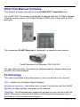
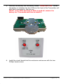
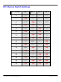
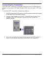
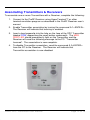
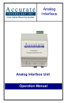
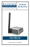
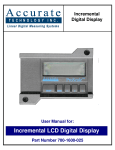
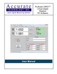
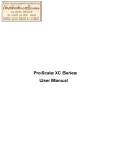
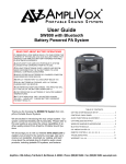
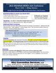
ProRF SPC
Transmitter
User Manual
Firmware version 1.0 and greater
FCC NOTICE
This equipment has been tested and found to comply with the limits for a class
B digital device, pursuant to part 15 of the FCC Rules. These limits are
designed to provide reasonable protection against harmful interference in a
residential installation. This equipment generates, uses and can radiate radio
frequency energy and if not installed and used in accordance with the
instructions, may cause harmful interference to radio communications.
However, there is no guarantee that interference will not occur in a particular
installation. If this equipment does cause harmful interference to radio or
television reception, which can be determined by turning the equipment off and
on, the user is encouraged to correct the interference by one or more of the
following measures:
•
Reorient or relocate the receiving antenna.
•
Increase the separation between the equipment and the Receiver.
•
Connect the equipment to an outlet on a circuit different from that to
which the Receiver is connected.
•
Consult the dealer or an experienced radio/television technician for
help.
Operation with non-approved equipment is likely to result in interference to
radio and TV reception. The user is cautioned that changes and modifications
made to the equipment without the approval of the manufacturer could void the
user’s authority to operate this equipment.
ATTENTION
This Transmitter is compatible with ProRF
Receiver 700-1038-001 pictured below ONLY.
It CAN NOT be used with ProScale Receiver model
700-1036-0xx (with external antenna)
OK
ProRF SPC Transmitter User Manual
Page 2 of 16
WARRANTY
Accurate Technology, Inc., warrants this product against defective parts and
workmanship for 1 year commencing from the date of original purchase. Upon
notification of a defect, Accurate Technology, Inc., shall have the option to
repair or replace any defective part. Such services shall be the customer'
s sole
and exclusive remedy.
Expenses incidental to repair, maintenance, or
replacement under warranty, including those for labor and material, shall be
borne by Accurate Technology, Inc. (Including freight or transportation charges
during the first 30 days).
Except as expressly provided in this warranty, Accurate Technology, Inc., does
not make any warranties with respect to the product, either expressed or
implied, including implied warranties of merchantability or fitness for a particular
purpose, except as expressly provided in this agreement.
Accurate Technology, Inc., shall not be liable for any special, incidental, or
consequential damages or for loss, damage or expense directly or indirectly
arising from the customer'
s use of or inability to use the equipment either
separately or in combination with other equipment, or for personal injury or loss
or destruction of other property, or from any other cause.
To request repair work (either warranty qualified parts or not), contact Accurate
Technology, Inc. directly by phone, fax, or e-mail. A Returned Merchandise
Authorization (RMA) number is required before returning a product for repair.
This document is protected by the copyright laws of the United States of
America. No part of this document may be reproduced by any means,
electronic or otherwise, without the expressed written permission of
Accurate Technology, Inc.
+1 828.654.7920 800.233.0580
828.654.8824 (F)
www.proscale.com
[email protected]
Copyright © 2004-2007,
Accurate Technology, Inc. All rights reserved.
P/N 800-1342-001, Revision A,
Firmware Version 1.000
Accurate Technology Inc.
Page 3 of 16
Table of Contents
FCC NOTICE .............................................................................................. 2
WARRANTY ............................................................................................... 3
SECTION 1
GENERAL INFORMATION.................................................. 5
INTRODUCTION .......................................................................................... 5
WHAT THIS MANUAL CONTAINS ................................................................... 6
TERMINOLOGY .......................................................................................... 6
SECTION 2
INSTALLATION .................................................................. 7
SETTING THE RF CHANNEL ......................................................................... 7
RF Channel DIP Switch Settings .......................................................... 9
CONNECTING THET RANSMITTER..................................................................10
SECTION 3
ASSOCIATION ..................................................................11
ASSOCIATING TRANSMITTERS & RECEIVERS .................................................12
SECTION 4
OPERATION......................................................................13
BATTERY REPLACEMENT ...........................................................................14
ProRF SPC Transmitter User Manual
Page 4 of 16
SECTION 1
GENERAL INFORMATION
Introduction
Thank you for purchasing the ProRF SPC Transmitter. This radio Transmitter
unit is designed to be used in conjunction with Accurate Technology, Inc.
ProScale® linear measuring systems and the Accurate Technology, Inc. ProRF
Receiver.
The purpose of this system is to provide a two-way wireless communication
channel between any ProScale measuring system with a 10 pin SPC output
and a computer or other computing device.
10 pin SPC output
The following is a list of features for the ProRF SPC Transmitter:
•
2.4 GHz radio transceiver providing two-way RF communications using
the industry standard 802.15.4 communications protocol.
•
2 LEDs provide RF message status and low battery reporting.
•
Operates from a single lithium coin cell battery.
•
3 to 6+ months battery lifetime depending on usage.
•
Sixteen selectable RF channels for interference free operation.
•
Typical RF signal range: 50’ to 100’ depending on the environment.
•
Small, compact enclosure designed to plug into ProScale Digital
Readouts (DROs) that are equipped with an SPC data port.
Accurate Technology Inc.
Page 5 of 16
What This Manual Contains
This manual includes information on the ProRF SPC Transmitter only.
The ProRF SPC Transmitter is designed to operate with any ProScale General
Purpose surface mount LCD Digital Readout (DRO) that is built with an SPC
data port.
The companion ProRF Receiver is reviewed in a separate user manual.
ProRF Receiver Part Number: 700-1038-001
For operation and other information on related products, please refer to the
manuals for those products.
Terminology
This section provides a brief description of terms used within this manual.
DRO – Refers to a ProScale Digital Readout.
Association/Learning – Associates one or more Transmitters with the ProRF
Receiver to allow position messages to be received.
TigerStop – An automated saw stop fence system that can interface with the
ProRF Receiver to automatically build cut-list based measurements from a
ProScale or ProPanel Measuring System.
ProRF SPC Transmitter User Manual
Page 6 of 16
SECTION 2
INSTALLATION
Setting the RF Channel
The ProRF SPC Transmitter can be configured to operate on 1 of 16 possible
radio frequency channels. The default channel is 0.
Unless there are other ProRF systems in range that could cause a
conflict, the default channel setting of 0 should be used.
Note: If the Transmitter’s RF channel is changed from its default setting,
the Receiver’s RF channel must also be changed.
To change the channel, complete the following steps. If the default channel is
to be used, skip to Connecting the Transmitter (page 10).
1. Using a Phillips screwdriver, remove the two screws from the back of
the housing.
2. Touch a grounded metal surface to discharge any static electricity from
your body, and then remove the front and back cover of the Transmitter
enclosure.
3. Slide out the coin cell battery from the battery holder and set it aside.
4. Locate the address switch in the lower left hand corner of the circuit
board. Set the desired channel using the dip switch. The table on the
page 9 illustrates the switch setting versus the channel number.
RF Channel Switch
Accurate Technology Inc.
Page 7 of 16
5. Reinstall the battery into the battery holder. PLUS side is UP. When
the battery is installed, the two LEDs on the front of the Transmitter will
both flash momentarily, then go out.
NOTE: If the LEDs continue to flash on and off, remove the
battery for 10 seconds and then re-install it.
6. Install the circuit board into the enclosure and secure with the two
Phillips head screws.
ProRF SPC Transmitter User Manual
Page 8 of 16
RF Channel Switch Settings
RF Channel
SW 1
SW 2
SW 3
SW 4
0
OFF
OFF
OFF
OFF
1
ON
OFF
OFF
OFF
2
OFF
ON
OFF
OFF
3
ON
ON
OFF
OFF
4
OFF
OFF
ON
OFF
5
ON
OFF
ON
OFF
6
OFF
ON
ON
OFF
7
ON
ON
ON
OFF
8
OFF
OFF
OFF
ON
9
ON
OFF
OFF
ON
10
OFF
ON
OFF
ON
11
ON
ON
OFF
ON
12
OFF
OFF
ON
ON
13
ON
OFF
ON
ON
14
OFF
ON
ON
ON
15
ON
ON
ON
ON
Accurate Technology Inc.
Page 9 of 16
Connecting the Transmitter
The ProRF SPC Transmitter is designed to operate with any ProScale general
purpose surface mount LCD Digital Readout (DRO) that has a built in SPC data
port.
To install the SPC Transmitter, complete the following:
1. Peel off the backing of the pressure sensitive double faced tape located
on the side of the Transmitter housing.
2. Plug the 10 pin header from the SPC Transmitter into the side of the
ProScale DRO’s SPC data port. Be sure that all of the pins are
properly aligned.
3. Press the Transmitter enclosure securely against the DRO housing to
ensure that the double faced tape contacts both units adequately.
ProRF SPC Transmitter User Manual
Page 10 of 16
SECTION 3
ASSOCIATION
Each ProRF SPC Transmitter is assigned a unique 64-bit ID that identifies that
Transmitter to a Receiver. For proper communication to occur between the
Transmitter and Receiver, each Transmitter in the system must be associated
or “learned” by the Receiver.
The association process is a one time operation where the Receiver is placed
into a special mode which listens for new Transmitters to be acquired. To learn
a particular Transmitter, the user then activates a “learn” pushbutton on the
desired Transmitter. The Transmitter sends its unique 64-bit ID which the
Receiver then stores in its permanent memory. Following this operation, the
Receiver will accept messages from any learned Transmitter and reject
messages from unknown Transmitters.
If you purchased this SPC Transmitter as a system, i.e. with a ProRF
Receiver, the Receiver and Transmitter(s) have already been associated
at the factory during final testing. If you have purchased this Transmitter
separately, you will have to associate it with your ProRF Receiver.
The association procedure is outlined below. Additional information regarding
this operation can also be found in the ProRF Receiver user’s manual.
Accurate Technology Inc.
Page 11 of 16
Associating Transmitters & Receivers
To associate one or more Transmitters with a Receiver, complete the following:
1. Connect to the ProRF Receiver using HyperTerminal™ or other
terminal emulation program as described in the ProRF Receiver user’s
manual.
2. Enable Transmitter association by issuing the command A 1<ENTER>.
The Receiver will indicate that learning is enabled.
3. Insert a bent paperclip into the hole on the face of the SPC Transmitter
labeled PGM, depressing the small button underneath. The MSG
SENT LED should momentarily light on the Transmitter and the
Receiver will send the following message to the PC: “Transmitter
Learned”. The association is now complete.
4. To disable Transmitter association, send the command A 0<ENTER>
from the PC to the Receiver. The Receiver will indicate that
Transmitter association is now disabled.
ProRF SPC Transmitter User Manual
Page 12 of 16
SECTION 4
OPERATION
To send a position message from the ProScale DRO to the ProRF Receiver,
press the SEND button on the DRO. The DRO LCD will display “Snd” for 1
second.
If the transmission is successful, the MSG SENT LED on the SPC Transmitter
will flash very briefly, about 1/10 second. The ProRF Receiver will momentarily
display the Transmitter ID along with a flash of the POS MSG LED.
SEND button location
(depends on DRO version)
Transmitter ID Displayed
If the transmission was not successful, the MSG SENT LED on the SPC
Transmitter will flash for a longer time, about 1 ½ seconds. If this occurs, the
user should try to retransmit again by pressing the SEND button on the DRO. If
the error continues, a range issue or interference may be preventing the
transmission from being received. Move the DRO closer to the Receiver and
attempt the transmission again.
Each time the SEND button on the DRO is depressed, the SPC Transmitter will
send a new position message to the Receiver.
The user can also activate a special delete function that will transmit a special
message to the ProRF Receiver. This message will cause a delete last
measurement signal to be sent to the PC or TigerStop. In the case of a PC, it
causes a DELETE text message to be displayed. When using a TigerStop, it
causes the last entry in the cut list to be deleted. To activate the delete
function, press the F2 button on the DRO.
NOTE: The delete function only operates with ProScale DROs that have
firmware version 2.x9 or above.
Accurate Technology Inc.
Page 13 of 16
Battery Replacement
Periodically, the coin cell battery in the SPC Transmitter will require
replacement. A low battery condition is detected by the Transmitter and will be
indicated by flashing the LOW BAT LED when a position message is sent. A
low battery condition still allows normal operation but the transmission range
may be diminished. Change the battery as soon as possible by completing the
following:
1. Unplug the SPC Transmitter from the side of the ProScale DRO.
2. Using a Phillips screwdriver, remove the two screws from the back of
the housing.
3. Touch a grounded metal surface to discharge any static electricity from
your body, and then remove the back cover of the Transmitter
enclosure.
4. Slide out the coin cell battery from the battery holder.
5. Install a new CR2450 (or equivalent) lithium battery into the battery
holder with the PLUS side UP. When the battery is installed, the two
LEDs on the front of the Transmitter will both flash momentarily.
NOTE: If the LEDs continue to flash on and off, remove the
battery for 10 seconds and then re-install it.
6. Re-install the rear enclosure cover and replace the screws.
7. Plug the SPC Transmitter into the DRO’s SPC data port, ensuring the
pins are correctly aligned.
ProRF SPC Transmitter User Manual
Page 14 of 16
Product Registration
Fill out for your records and
FAX to Accurate Technology @ +1.828.654.8824
Or register online at: www.proscale.com/registration.htm
Name
E-Mail
Company
Address
Address
City
State/Region
Zip/Postal Code
Country
Purchased From:
Purchased When:
Serial Number:
Accurate Technology Inc.
Page 15 of 16
Thank you for choosing an Accurate
Technology Product
MADE IN USA
Accurate Technology, Inc.
270 Rutledge Rd. Unit E
Fletcher, NC 28732 USA
800 233-0580 • 828-654-7920
Fax 828-654-8824
www.proscale.com
[email protected]
This manual is available at www.proscale.com
Please return your Product Registration Card
or register your system at:
www.proscale.com/registration.htm
P/N 800-1342-001, Revision A, Copyright © 2007, Accurate Technology,
Inc. All rights reserved.
ProRF SPC Transmitter User Manual
Page 16 of 16