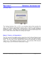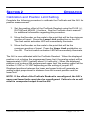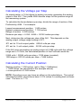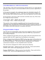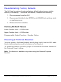
1
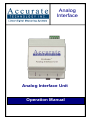
Analog
Interface
Analog Interface Unit
Operation Manual
WARRANTY
Accurate Technology, Inc. warrants the product against defective parts and
workmanship for 1 year commencing from the date of original purchase.
Upon notification of a defect, Accurate Technology, Inc., shall have the
option to repair or replace any defective part. Such services shall be the
customer's sole and exclusive remedy. Expenses incidental to repair,
maintenance, or replacement under warranty, including those for labor and
material, shall be borne by Accurate Technology, Inc. (Including freight or
transportation charges during the first 30 days).
Except as expressly provided in this warranty, Accurate Technology, Inc.
does not make any warranties with respect to the product, either expressed
or implied, including implied warranties of merchantability or fitness for a
particular purpose, except as expressly provided in this agreement.
Accurate Technology, Inc. shall not be liable for any special, incidental, or
consequential damages or for loss, damage or expense directly or indirectly
arising from the customer's use of or inability to use the equipment either
separately or in combination with other equipment, or for personal injury or
loss or destruction of other property, or from any other cause.
To request repair work, (either warranty qualified parts or not) follow the
directions at www.proscale.com. A Returned Merchandise Authorization
(RMA) number is required before returning any product for repair.
SAFETY WARNING
Before installing this product:
Turn off and disconnect all power.
SAFETY WARNING
Accurate Technology, Inc.
+1 828.654.7920
800.233.0580 828.654.8824 (F)
www.proscale.com
[email protected]
Manual P/N 800-1406-001
Copyright © 2011 Accurate Technology, Inc. All rights reserved
Accurate Technology Analog Interface
Page 2 of 12
Table of Contents
SECTION 1
GENERAL INFORMATION
4
INTRODUCTION ............................................................................................ 4
BASIC THEORY OF OPERATION ..................................................................... 4
SPECIFICATIONS .......................................................................................... 5
TERMINAL BLOCK......................................................................................... 5
MOUNTING .................................................................................................. 5
MAKING CONNECTIONS ................................................................................ 6
SECTION 2
OPERATION
7
CALIBRATION AND POSITION LIMIT SETTING .................................................. 7
CALCULATING THE VOLTAGE PER STEP ......................................................... 8
CALCULATING THE CURRENT POSITION: ........................................................ 8
CONSIDERATIONS IN A/D CONVERSIONS ....................................................... 9
PROGRAMMABLE OUTPUT ............................................................................ 9
RE-ESTABLISHING FACTORY DEFAULTS ...................................................... 10
Factory Default Values ........................................................................ 10
POWERING A PROSCALE READOUT ............................................................ 10
Manual Part # 800-1406-001
Page 3 of 12
SECTION 1
GENERAL INFORMATION
Introduction
The Analog Interface Unit, or AIU, is an interface device that provides the
user of a ProScale measurement system with a method of generating an
analog DC output voltage that is proportional to the currently displayed
ProScale position. This output can be used with an A/D converter input on a
PLC or other device that utilizes an analog input signal.
Basic Theory of Operation
The AIU converts the digital position signal from the ProScale Readout and
compares it to an internal pre-programmed set of lower and upper position
limits. The AIU uses a ratio utilizing these factors and generates an analog
output via a 12-bit digital-to-analog converter. This provides 4096 discrete
voltage steps over the defined measurement range.
Accurate Technology Analog Interface
Page 4 of 12
Specifications
Dimensions:
2.75 x 3.38 x 2.27 In. (70 x 86 x 57 mm)
Power:
12-24 VDC @ 100mA (max)
Power connector:
Terminal Screw Block
Input:
Synchronous serial BCD (Mitutoyo Digimatic®)
Output:
0 - 5 or 0 - 10 VDC, 60 mA
Terminal Block
Position 1
Positive 12 to 24 VDC
Position 2
Ground
Position 3
Analog voltage output
Position 4
Ground
Position 5
Programmable output, active LOW
(encoder failure or Readout SEND button)
Mounting
The AIU is mounted via a standard 35 mm wide DIN rail. This can be either
7.55 mm or 15 mm height. A quick release latch can be disengaged using a
small flat screwdriver and pulling on the latch tab located on the bottom of
the AIU housing
Manual Part # 800-1406-001
Page 5 of 12
Making Connections
NOTE: DO NOT APPLY POWER UNTIL ALL CONNECTIONS HAVE BEEN
COMPLETED.
1. Connect 12 to 24 VDC to terminals 1 and 2.
Terminal 1 is positive.
Terminal 2 is ground and must share common ground with the PLC.
2. Connect the analog output terminals 3 and 4 to the analog input of
the PLC or other control device.
Terminal 3 is positive.
Terminal 4 is ground.
3. Optionally, connect the programmable output on terminal 5 to a
digital input of the PLC or control device.
4. Connect the 10 pin cable between the ProScale Readout SPC
Output and the AIU Input. The cable connectors are keyed for
proper alignment.
5. Remove the snap-on cover from the AIU by squeezing the sides of
the top cover and set the analog output configuration jumper
JP1 across pins 1 & 2 for 0-10 volts output
JP1 across pins 2 & 3 for 0-5 volts output.
6. Optionally, install a jumper on JP2 for a supply voltage pull-up if
needed on the output.
If JP2 is left open, the AIU will provide a ground signal when an
encoder fault/SEND button is active. When normal, the output is
high impedance.
If a jumper is installed on JP2, the normal output will be pulled up to
the supply voltage via a 10K ohm resistor.
7. Apply power to the AIU. The two indicators should momentarily light
up to indicate operation. If the ProScale Readout is connected
properly, the status LED will illuminate.
Accurate Technology Analog Interface
Page 6 of 12
SECTION 2
OPERATION
Calibration and Position Limit Setting
Complete the following procedure to calibrate the ProScale and the AIU for
position measurement.
1. Set the position offset of the ProScale Readout using the PLUS (+),
DATUM and MINUS (-) buttons. See the ProScale user’s manual
for additional information regarding this procedure.
2. Move the Encoder on the scale to the point that will be the minimum
position of travel. Press the Lower Limit pushbutton on the AIU.
The limit switch activation LED will momentarily illuminate.
3. Move the Encoder on the scale to the point that will be the
maximum position of travel. Press the Upper Limit pushbutton on
the AIU. The limit switch activation LED will momentarily illuminate.
The AIU is now calibrated with the ProScale Readout. When the displayed
position is at or below the programmed lower limit, the analog output will be
approximately 0 VDC (typically about 3-4 millivolts.) When the displayed
position is at or above the programmed upper limit, the analog output will be
at either 5 VDC or 10 VDC depending on the setting of jumper JP1.
Displayed positions between the lower and upper limits will generate an
analog output proportional to distance from the current position and the
lower limit.
NOTE: If the offset of the ProScale Readout is reconfigured, the AIU’s
upper and lower limits must also be reconfigured. Failure to do so will
result in unexpected output from the AIU.
Manual Part # 800-1406-001
Page 7 of 12
Calculating the Voltage per Step
As stated earlier, a 12-bit digital-to-analog converter generates the analog
output of the AIU. This yields 4096 discrete steps for the position range of
the measuring system.
To calculate the linear distance per step, divide the range of motion of the
ProScale by 4096. For example:
Lowest measurement position: 1.500 inches
Highest measurement position: 7.750 inches
Range of motion: 6.250 inches
Distance per step =: 6.250 / 4096 = .00152 inches per step.
Next, determine the voltage per step of the AIU. This depends on the
analog output voltage range setting of JP1.
JP1 set for 10 volt output yields: .00244 volts per step.
JP1 set for 5 volt output yields: .00122 volts per step.
If the AIU were generating an analog output of 2.999 volts with the voltage
range set to 10 volts, the calculated position of the ProScale would be:
2.999 volts / .00244 volts per step = 1229 steps (rounded).
1229 steps x .00152 Inches per step = 1.868 inches.
Calculating the Current Position:
Starting position: 1.500 inches (set in Step 1 Calibration)
+ 1.868 inches (as calculated in the example above)
= a new position of 3.368 inches
NOTE: Rounding errors can have an effect on the calculations. The actual
calculated position should have been 3.374 inches if rounding had not been
used. The error is .17%
Accurate Technology Analog Interface
Page 8 of 12
Considerations in A/D Conversions
The resolution of the A/D converter being used by the PLC or control device
will have a direct impact on the measurement and conversion capabilities of
the system.
In the previous example, the voltage per step was calculated using the 12bit resolution capability of the AIU. If the PLC or control device utilizes an
A/D converter with a different resolution, then that resolution must be used.
As an example, if the PLC’s A/D converter resolution was only 10-bit, then
the voltage per step would be:
10 volt range / 1024 = .00976 volts per step
5 volt range / 1024 = .00488 volts per step
This results in less resolution capability and thus less position accuracy
capability when calculating the ProScale Measurment System’s position. In
summation, the resolution of the PLC’s A/D converter should be at least 12bit or higher to provide maximum conversion accuracy.
Programmable Output
The AIU has a programmable output that can be used for either an encoder
fault output or an output that activates when the SEND key is pressed on
the ProScale Readout.
When configured for Encoder Fault, the output of the AIU will transition low
(ground) when the SPC signal from the Readout is interrupted.
When configured for the Readout SEND button, the output will transition low
for approximately 100 milliseconds when the SEND button is depressed on
the ProScale Readout. This can be useful in signaling the PLC when a
measurement sample is to be completed and/or recorded.
The unit can be configured for either mode by the following:
Encoder Fault output – Remove power from the AIU. Press and hold the
UPPER LIMIT switch while applying power to the AIU.
Readout SEND Button - Remove power from the AIU. Press and hold the
LOWER LIMIT switch while applying power to the AIU.
Manual Part # 800-1406-001
Page 9 of 12
Re-establishing Factory Defaults
The AIU has the option of restoring factory default values in non-volatile
memory if necessary. To activate this feature, complete the following:
1. Remove power from the AIU.
2. Depress and hold both the UPPER and LOWER limit switches while
re-applying power.
3. Release the limit switches.
Factory Default Values
Lower Position Limit – 0.000 inches
Upper Position Limit – 4.000 inches
Programmable Output Function – Encoder Failure
Powering a ProScale Readout
You may power a ProScale Readout directly from the AIU via the SPC cable
thereby eliminating the need for batteries in the Readout.
To enable this feature, move the jumper JP4 inside the ProScale Readout to
the ‘External Power” setting.
Note: This feature is available only when using the General Purpose
Readout.
Accurate Technology Analog Interface
Page 10 of 12
This page left intentionally blank
Manual Part # 800-1406-001
Page 11 of 12
Thank you for choosing an
Accurate Technology Product
This product was proudly MADE IN USA
Accurate Technology, Inc.
270 Rutledge Rd. Unit E
Fletcher, NC 28732 USA
800 233-0580 • 828-654-7920
Fax 828-654-8824
www.proscale.com
[email protected]
Please register your system at:
http://www.proscale.com/registration.htm
This manual is available at www.proscale.com
Manual P/N 800-1406-001
Copyright © 2011 Accurate Technology, Inc. All rights reserved
Accurate Technology Analog Interface
Page 12 of 12