1
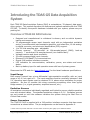
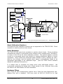
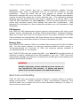
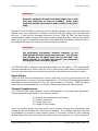
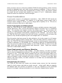
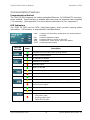
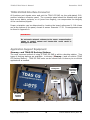
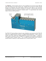
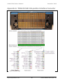
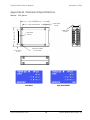
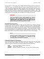
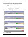
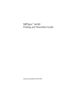
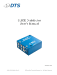
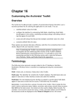
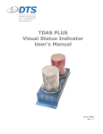
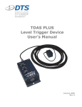
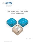
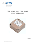
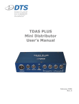
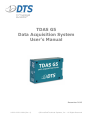
1720 Apollo Court Seal Beach, CA 90740 USA Phone: +1 562 493 0158 Fax: +1 562 493 3158 www.dtsweb.com TDAS G5 Data Acquisition System User’s Manual December 2013 11000-00010-MAN (Rev. 4) ©Diversified Technical Systems, Inc. - All Rights Reserved TDAS G5 DAS User’s Manual December 2013 Table of Contents DTS Support .................................................................................................... 3 Overview of TDAS G5 DAS Features ................................................................ 4 Input Range ...................................................................................................4 Excitation Sources ...........................................................................................4 Sensor Connectors ..........................................................................................4 Shunt Calibration Resistors ...............................................................................5 Shunt Emulation..............................................................................................5 Hardware Filters ..............................................................................................5 EID Support....................................................................................................6 Memory Size ...................................................................................................6 Basic Care and Handling ................................................................................. 6 Shock Rating ..................................................................................................7 Thermal Considerations ....................................................................................7 Power Considerations ..................................................................................... 8 Power Consumption and Management ................................................................8 Power Requirements and Memory Retention .......................................................8 External Power Provisions .................................................................................8 Communication Features ................................................................................ 9 Communication Method ....................................................................................9 LED Indicators ................................................................................................9 TDAS G5 DAS Interface Connector ................................................................ 10 Application Support Equipment ..................................................................... 10 iDummy™ and TDAS G5 Docking Stations ....................................................... 10 Appendix A: TDAS G5 DAS 216-position Interface Connector ....................... 12 Appendix B: Mechanical Specifications ......................................................... 13 Appendix C: Changing the TDAS G5 DAS Network Parameters ..................... 14 Establish Communication ................................................................................ 14 Change the Network Parameters ..................................................................... 14 Using the New Settings .................................................................................. 16 Appendix D: Hardware Configuration Specifications .................................... 17 [email protected] ii 11000-00010-MAN (Rev. 4) TDAS G5 DAS User’s Manual December 2013 DTS Support TDAS G5 systems are designed to be reliable and simple to operate. Should you need assistance, DTS has support engineers worldwide with extensive product knowledge and test experience ready to help via telephone, e-mail or on-site visits. The best way to contact a DTS support engineer is to e-mail [email protected]. Your e-mail is immediately forwarded to all DTS support engineers worldwide and is typically the fastest way to get a response, particularly if you need assistance outside of normal business hours. For assistance by telephone, please go to http://dtsweb.com/support/techsupport.php to find the phone number appropriate for your region of the world. Additional self-help resources and support material can be found at www.dtsweb.com. All DTS software installs user manuals to support a variety of products; these are available under the Help menu. This manual supports the following products: 11000-00010: TDAS G5 DAS module (32 ch) 11000-00020: TDAS G5 DAS module, high bandwidth (32 ch) [email protected] 3 11000-00010-MAN (Rev. 4) TDAS G5 DAS User’s Manual December 2013 Introducing the TDAS G5 Data Acquisition System Each TDAS G5 Data Acquisition System (DAS) is a standalone, 32-channel, data acquisition system. This manual discusses the features and options available with the TDAS G5 DAS. To identify the specific hardware included with your system, please see your packing list. Overview of TDAS G5 DAS Features Designed and manufactured to withstand in-dummy and on-vehicle dynamic testing environments. 32 programmable sensor input channels, each with an independent excitation source, true differential instrumentation amplifier, anti-alias filter, 16-bit analogto-digital converter, and electronic identification (EID) support. 1 to 100 kHz sampling rate – adjustable. Primary memory: 150 seconds* at 10k samples/second (RAM); back-up memory: 7 seconds at 10k samples/second (non-volatile flash). Voltage insertion and shunt emulation. 32 multi-purpose digital input channels. Ethernet 10/100BaseT/Tx communications. Simple 216-position interface connector. LED indicators for communication, calibration, power, arm status and event status. Back-up battery input for safe operation even with loss of primary power. Please see the DTS web site (www.dtsweb.com) for the latest hardware specifications. Input Range Each sensor channel has a true differential instrumentation amplifier with an input range of ±2.0 V at a gain of 1. The input amplifiers function nominally between 0 and 5 V, therefore input signals must be centered 2.5 V above minus excitation for proper operation. Be sure to consider this when connecting something other than typical bridge sensors (i.e., signal generator, amplified sensors, etc.). Excitation Sources All excitation sources are individually regulated and limited to ensure reliable operation even with shorted cables. The standard excitation voltage is 5.0 V. Excitation sources are not turned on until the software initializes the system during the Real-Time or Collect Data modes. Sensor Connectors The TDAS G5 DAS is supplied with a 216-position interface connector that has sensor connections as shown below. The pin assignments can be found in Appendix A. * Earlier units may contain less RAM. See the section on Memory Size (page 6) for additional details. [email protected] 4 11000-00010-MAN (Rev. 4) TDAS G5 DAS User’s Manual December 2013 Excitation 5 V, 20 mA Excitation Check ADC Shunt Check Driver TDAS G5 DAS Sensor Connector Gain Calibration +Ex +Sig ID/digital Shield -Sig -Ex + Differential Instrumentation Amplifier - +Ex Dallas ID guide pin 2.5 V Ref R R +Sig R R -Sig -Ex +5 V Contact Closure Digital Inputs Dallas ID Interface 2004-2013Diversified Technical Systems, Inc. - All Rights Reserved Sensor Connections Shunt Calibration Resistors Conventional shunt calibration resistors are not supported in the TDAS G5 DAS. Shunt emulation is used to perform shunt checks. Shunt Emulation The TDAS G5 DAS uses shunt emulation to perform shunt checks. Shunt emulation eliminates the need for conventional shunt resistors and is enabled when “Emulation” is chosen in the SIF as the shunt calibration method. This method applies a precise current to a connected sensor and checks for expected deflection based on sensor impedance. Shunt checks are performed under software control; settings are calculated by the software and the applied shunt signal is automatically scaled to an appropriate percentage of the requested range. (See the TDAS Control software manual for additional information.) It is always best to complete the bridge when using half-bridge sensors. We recommend completing the bridge with a fixed resistor on the +Sig side, then using the value of the fixed resistor for shunt emulation. Hardware Filters Each TDAS G5 DAS measurement channel has a fixed four-pole Butterworth antialiasing filter with a standard -3 dB knee point at 4000 Hz (30,000 Hz for high [email protected] 5 11000-00010-MAN (Rev. 4) TDAS G5 DAS User’s Manual December 2013 bandwidth). Each channel also has a software-controlled, variable five-pole Butterworth filter, which is adjustable from 50 to 5000 Hz (30,000 Hz for high bandwidth). These two filters may be used together to provide an effective Butterworth response with up to nine poles. The TDAS Control software automatically chooses the best filter setting for a chosen sampling rate. (The relationship between sampling rate and anti-alias filter knee point is contained in a look-up table in the TDAS G5 DAS initialization file called tdas.ini.) DTS can provide assistance to help ensure that end-users employ filter settings that meet their requirements. (See Appendix B for information on how to determine whether your unit is standard or high bandwidth.) EID Support Each TDAS G5 DAS measurement channel supports communication with silicon serial number devices manufactured by Dallas Semiconductor/Maxim Integrated Products. When you connect an ID chip to the proper pins on the sensor connector, the TDAS Control software can automatically read these devices and correlate the serial number with channel set-up information stored in a Sensor Information File (SIF). Memory Size Each TDAS G5 DAS contains 5 MB of non-volatile flash memory and 100 MB of volatile RAM. For each sensor channel, the maximum samples available via flash memory is 10k samples/second for 7 seconds; for RAM, the maximum samples available is 10k samples/second for 150 seconds. Early TDAS G5 DAS units may contain less RAM. Your tdas.ini file provided at time of shipment is properly configured for the RAM available in your unit. TDAS Control will automatically calculate the maximum recording time possible given the sampling rate selected and the RAM available. WARNING: Reliable, high-quality, primary and back-up power sources are very important for data retention. If primary and back-up power is lost, all data contained in the RAM will be deleted. Basic Care and Handling TDAS G5 DAS units are precision devices designed to operate reliably in dynamic testing environments. Though resistant to many environmental conditions, care should be taken not to subject the unit to harsh chemicals, submerge it in water, or drop it onto any hard surface. [email protected] 6 11000-00010-MAN (Rev. 4) TDAS G5 DAS User’s Manual December 2013 WARNING: Electronic equipment dropped from desk height onto a solid floor may experience as much as 10,000 g. Under these conditions, damage to the exterior and/or interior of the unit is likely. Should a TDAS G5 DAS be removed from its docking station, we recommend that you always cover the 216-position interface connector with the rubber cap provided with the unit. If you feel the interface connector on your TDAS G5 DAS unit has become contaminated, please contact DTS support before attempting any cleaning procedure. When not in use or if shipping is required, we suggest that you always place the unit in the padded carrying case originally provided with your system. WARNING: The gold-plated, 216-position interface connector on the TDAS G5 DAS should be treated with great care. It is through this interface that all signals enter and exit the DAS. Any debris, solvents, or oil (even from fingers), can compromise the integrity of the connections/signals. The TDAS G5 DAS is supplied with calibration data from the factory. DTS recommends annual recalibration to ensure that the unit is performing within factory specifications. It is not user-serviceable and should be returned to the factory for service or repair. Shock Rating TDAS G5 DAS units are designed to function routinely in a 500 g environment such as that experienced in severe in-dummy applications. All vehicle-/sled-mounted systems are rated for and fully tested to 100 g, 12 msec duration, in all axes. TDAS G5 equipment can be mounted directly on a vehicle, sled or other dynamic testing device. Thermal Considerations The TDAS G5 DAS uses extensive power management to minimize heat generation. Temperature will be affected by four primary factors: 1) 2) 3) 4) Ambient air temperature and airflow, Sunlight exposure, Sensor load, and Length of time armed. Since the system draws the most power when armed, running the calibrations and arming as late as possible will minimize self-heating. It is unlikely that the units will be damaged by excessive heat because power is internally limited by self-resetting thermal fuses―the units will simply shut down when they get too hot. Most implemen- [email protected] 7 11000-00010-MAN (Rev. 4) TDAS G5 DAS User’s Manual December 2013 tation scenarios use one of the two available TDAS G5 docking stations, either of which provide an adequate heat sink under normal operating conditions. If two or more of the above factors will cause case temperatures in excess of 50°C, the airflow created by a small fan will increase heat transfer by a factor of 3 to 5. Additionally, always shield the units from exposure to direct sunlight. Power Considerations A good power source is of paramount importance. Each TDAS G5 DAS should be powered from a fully-charged, 12 V battery or a high-quality power supply with a nominal output voltage of 13.8 V (11-15 V range) and a capacity of 2 A. Be sure to consider any power drop due to cable length. Power Consumption and Management When the TDAS G5 DAS is initially powered, all sensor excitation sources, signal conditioning electronics, filter circuits and analog-to-digital converters are in a shutdown state. The processor and support circuitry are always powered. The processor will remain in a reduced power state when not performing tasks. When the user runs a test set-up, the software automatically energizes all 32 channels. The current draw per TDAS G5 DAS will increase from 190 mA at idle to as much as 800 mA when the system is fully armed and powering 350 ohm bridges with 5 V excitation. Once the system has been armed for data collection, all circuits remain in a full power state until the system finishes storing data. After the data collection routine is complete, the TDAS G5 DAS de-energizes several circuits to minimize power consumption. It takes a maximum of 125 seconds (for 70 seconds of data at 10k samples/second) after the end of the data storage window for the TDAS G5 DAS to return to the idle state, which then allows communication and download. (Note: Data from multiple DAS units is downloaded serially.) Power Requirements and Memory Retention RAM is the primary means for data storage. The flash memory is a back-up system used to store a predetermined portion of the test data in case both primary and backup power is lost. (This data subset contains both pre- and post-trigger data up to 5 MB. Users should select the pre-event time carefully to ensure that the post-event region-of-interest is also included and written to flash.) If power is lost after flash memory has been written, the data contained in the flash can be downloaded after power is restored. External Power Provisions The TDAS G5 DAS does not contain any internal power source, but has connector inputs for both primary and back-up power sources. Actual useful back-up capacity will depend upon the number of channels in use, the resistance of the connected sensors, the supply’s rating and whether or not it was fully charged before testing. [email protected] 8 11000-00010-MAN (Rev. 4) TDAS G5 DAS User’s Manual December 2013 Communication Features Communication Method The TDAS G5 DAS supports the industry-standard Ethernet 10/100BaseT/Tx communication method. Communication is enabled after the power-up sequence has completed (~20 seconds). (See Appendix D for the network parameters of your equipment.) LED Indicators The TDAS G5 DAS has five LEDs (red/yellow/green) which provide ongoing status information. LED behavior is summarized in the table below. COM: Provides communication status with the docking station and DAS. CAL: Provides calibration status. PWR: Provides status on power to the DAS. ARM: Provides arm, start record, and event status. STAT: Provides general status. TDAS G5 DAS LED State Description Computer communicating with docking station No active communication All calibrations passed Calibration in progress Calibration fault Power on and OK Power warning (9.6 – 10.2 V) Power critical (<9.6 V) System armed and waiting for start record or event signal Received start record signal; waiting for event signal TDAS G5 DAS no longer armed or no longer collecting data or received event signal No faults detected Received event signal Fault occurred, either: - Low power input - Docking station fault - TDAS G5 DAS fault [email protected] 9 11000-00010-MAN (Rev. 4) TDAS G5 DAS User’s Manual December 2013 TDAS G5 DAS Interface Connector All functions and signals enter and exit the TDAS G5 DAS via the gold-plated, 216position interface connector panel. The connector panel should be treated with great care as any debris, solvents, or oil (even from fingers), can compromise the integrity of the connections/signals. Proper orientation can be determined by locating the board references J1-J18—these are at the bottom of the panel, closest to sensor channels 17-32. Pin assignments can be found in Appendix A. WARNING: Do not apply external voltages to the event, communication, status or control output and inputs—this could result in damage to the unit. Application Support Equipment iDummy™ and TDAS G5 Docking Stations The most common method of using a TDAS G5 DAS is within a docking station. Two types of docking stations are available: in-dummy (iDummy™) and on-vehicle (TDAS G5 Docking Station). TDAS G5 DAS units can be moved from in-dummy to on-vehicle applications as needed. Interposer Connector interface panel Flex circuit cable In-dummy docking station In-dummy Docking Station Configuration [email protected] 10 11000-00010-MAN (Rev. 4) TDAS G5 DAS User’s Manual December 2013 The iDummy™ docking station allows for easy installation and removal of the TDAS G5 DAS into virtually any crash dummy type. Signals enter and exit the TDAS G5 DAS through the interposer and pass through the flex circuit cable to the connector interface panel where the dummy’s sensors are connected. Communications are also accomplished through the connector interface panel. A single dummy can contain many in-dummy docking stations. Control panel Sensor connector panel with 32 LEMO connectors On-vehicle Docking Station The TDAS G5 Docking Station allows for easy installation and removal of the TDAS G5 DAS into a rugged enclosure useful for on-board testing applications. Power, communication and event signals are easily accessible via the control panel. A variety of larger sensor connectors, such as LEMO 1B or equivalent, can be easily connected via a compact sensor connector panel. The on-vehicle docking station also includes a powerful back-up battery for safe operation even if primary power is lost. [email protected] 11 11000-00010-MAN (Rev. 4) TDAS G5 DAS User’s Manual December 2013 Appendix A: TDAS G5 DAS 216-position Interface Connector [email protected] 12 11000-00010-MAN (Rev. 4) TDAS G5 DAS User’s Manual December 2013 Appendix B: Mechanical Specifications Weight: 200 grams 3.374 inches/85.7 mm 0.472 inches 12 mm 2.677 inches/68 mm 2.126 inches/54 mm 0.984 inches 25 mm 1.732 inches 44 mm 0.158 inches diam 4.0 mm diam 0.197 inches 5 mm TDAS G5 DAS, standard [email protected] TDAS G5 DAS, high bandwidth 13 11000-00010-MAN (Rev. 4) TDAS G5 DAS User’s Manual December 2013 Appendix C: Changing the TDAS G5 DAS Network Parameters TDAS G5 systems communicate using the industry-standard Ethernet protocol. Your TDAS G5 DAS was shipped with fixed IP address (myip) and subnet mask (netmask) parameters already loaded in the flash memory of the microcontroller. The steps below describe the process to change the DAS unit’s Ethernet parameters. Note: This process may require the help of your network administrator. If your in-house network support person is not available, we encourage you to contact DTS for help. CAUTION: Great care should be taken when changing any network parameters. The IP address and subnet mask should not be changed without full knowledge of the impact on the communication environment. If you have any questions, please contact your network administrator for help. Establish Communication Using the TDAS Firmware Loader provided with the TDAS Control software, establish communication with the DAS unit. To do this, change the fields to the appropriate hardware (G5), serial number of the DAS unit, and communication method (Ethernet). (You can ignore the IP address field for the moment.) Click on the “Discovery” button to search the network for the requested serial number. If the serial number is found, the IP address field will be updated with the current address for that DAS unit. (This step is performed to ensure that the computer and DAS unit are communicating.) NOTE: Both the computer and DAS unit must be on the same netmask for “Discovery” to be successful. If “Discovery” is not successful, please contact DTS for assistance. Change the Network Parameters Once communication has been established, use terminal mode from the Utility menu within the TDAS Control software to change the network parameters. The TDAS G5 DAS boot firmware recognizes the following standard firmware parameters: myip netmask gateway specifies the target’s IP address (required) subnet mask (required) gateway IP address (if needed – see your network administrator) [email protected] 14 11000-00010-MAN (Rev. 4) TDAS G5 DAS User’s Manual December 2013 The following commands are used to read and set the network parameters: fpget – Get parameter (print parameter from flash memory) Command fpget <name> - read parameter fpset – Set parameter (set parameter into flash memory) Command fpset <name> <value> - set parameter Confirm or change the “TDAS S/N” field. Type the command on the “Input Command” line. Click “GO” or hit the return key. fpset myip 192.168.0.124 The response is: FPSET: myip=192.168.0.124 To verify the change, type: fpget myip The response is: FPGET: myip=192.168.0.124 Click on “EXIT” when finished. [email protected] 15 11000-00010-MAN (Rev. 4) TDAS G5 DAS User’s Manual December 2013 Using the New Settings Use the following steps to update the system with the new network parameters: 1. 2. 3. 4. 5. 6. 7. Reboot the hardware to force the system to use the new setting(s). Find the tdas.ini file in the TDAS Control program folder (normally c:\dts_tdas) and make a back-up copy called tdas_backup.ini. Edit the file tdas.ini using Notepad or any text editor. Find the line titled “Rack Inventory” and change the IP address associated with the serial number for the TDAS G5 DAS to the new address. Note: Change only the IP address and not the DAS unit’s serial number. This is how the software will know how to search for the DAS at the new IP address. Save the file. Confirm your computer’s Windows/network settings match the new TDAS G5 network parameter(s). If changes are required to your computer, please contact your network administrator for assistance. Start the TDAS Control software and confirm that the TDAS G5 DAS is found at the new IP address. [email protected] 16 11000-00010-MAN (Rev. 4) TDAS G5 DAS User’s Manual December 2013 Appendix D: Hardware Configuration Specifications This is a custom page provided at time of shipment. If you need information on the specifics of your equipment, please e-mail your request to [email protected] with the serial number(s) of the equipment and parameters you are asking about. [email protected] 17 11000-00010-MAN (Rev. 4) TDAS G5 DAS User’s Manual Date By 04 Dec 2013 EKK [email protected] December 2013 Description Updated DTS Support, Input Range, Hardware Filters and Memory Size sections. Updated Appendices D and A (swapped LED Indicators and Interface Connector). Replaced “pin-outs” with “pin assignments”. Updated boilerplate material. Updated company address. Added doc number. (Rev 4) 18 11000-00010-MAN (Rev. 4)