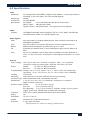
1
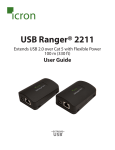
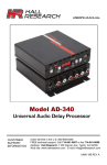
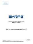
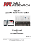
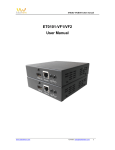
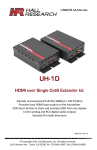
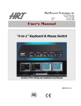
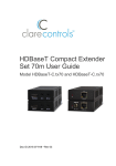
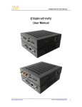
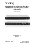
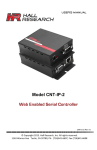
User’s Manual HDMI Video Extender with Bidirectional IR, and RS232 Send HDMI, IR, full-duplex RS232, and PoH Power 500 ft (150 m) on a single Cat6 cable Model numbers covered in this User’s Manual: Individual Ends UHBX-S-PSE HDMI+RS232+IR+PoH UTP Sender with Power Supply (PSE) UHBX-S-PD HDMI+RS232+IR+PoH UTP Sender Remotely Powered (PD) UHBX-R-PSE HDMI+RS232+IR+PoH UTP Receiver with Power Supply (PSE) UHBX-R-PD HDMI+RS232+IR+PoH UTP Receiver Remotely Powered (PD) Kits UHBX-P1 UHBX-P2 HDMI+RS232+IR+PoH UTP Extender, Sender (PSE) powers Receiver (PD) HDMI+RS232+IR+PoH UTP Extender, Receiver (PSE) powers Sender (PD) UMA1215 Rev n/c © Copyright 2013. Hall Research, Inc. All rights reserved. 1163 Warner Ave Tustin, CA 92780, Ph: (714)641-6607, Fax (714)641-6698 HDMI Extender with Power, IR, and RS-232 Table of Contents 1.0 Introduction ...................................................................................... 3 2.0 Features............................................................................................. 4 3.0 Model numbers covered in this Manual .......................................... 4 4.0 Setup .................................................................................................. 5 4.1 Package Contents.......................................................................... 5 4.2 Sender Connections ...................................................................... 5 4.3 Receiver Connections ................................................................... 8 4.4 Setting the Distance Mode............................................................ 9 4.5 LED indicators .............................................................................. 9 5.0 Troubleshooting ............................................................................... 10 6.0 Specifications .................................................................................... 11 TRADEMARKS USED IN THIS MANUAL Hall Research and its logo are trademarks of Hall Research. Any other trademarks mentioned in this manual are acknowledged as the property of the trademark owners. FCC RADIO FREQUENCY INTERFERENCE STATEMENT This equipment generates, uses, and can radiate radio frequency energy and if not installed and used properly, that is, in strict accordance with the manufacturer’s instructions, may cause interference to radio communication. It has been designed to comply with the limits for a Class A computing device in accordance with the specifications in Subpart B of Part 15 of FCC rules, which are intended to provide reasonable protection against such interference when the equipment is operated in a commercial environment. Operation of this equipment in a residential area is likely to cause interference, in which case the user at their own expense will be required to take whatever measures may be necessary to correct the interference. Changes or modifications not expressly approved by the party responsible for compliance could void the user’s authority to operate the equipment. 2 UHBX-Series 1.0 Introduction This manual covers a few of the UHBX series of HDMI extenders by Hall Research. These products are comprised of individual sender and receiver modules that can send HDMI, bidirectional IR, full-duplex RS232, and PoH (power over HDBaseT) over distances of up to 150 meters (500 feet) using a single Cat6 cable. The products can extend HDMI or single-link DVI video of virtually any resolution, to a maximum distance of 500 ft (150 m). Two user selectable distance modes are available: Standard and Long Reach. These modes are explained further in section 4.4 of this manual. The extenders comply with Power-over-HDBaseT or PoH, hence only one end requires a power supply. The end identified as PSE (power sourcing equipment) injects power on to the Cat6 cable and the side identified as PD (powered device) is powered through the Cat6 cable. The PSE side requires connection of an AC adapter that supplies 5v DC, while the PD side is simply powered through the RJ45 connector from the opposite side. Senders and Receivers are available in both PSE and PD versions. Prior to placing an order, it is important to determine which scenario works best for a given setup since the direction of power flow is determined by the model numbers ordered and cannot be reversed in the field. Figure 1 – Block Diagram for power sent from Sender to Receiver Figure 2 – Block Diagram for power sent from Receiver to Sender 3 HDMI Extender with Power, IR, and RS-232 Full-duplex RS232 Serial Port extension is provided that can operate at any baud rate to 115,200 (independent of video activity). The extender can also extend IR from one end to the other. IR Detector and IR Emitter cables are sold separately. The IR extension preserves the modulation (carrier) frequency and provides compatibility to virtually any standard. It supports modulation range from 30 KHz to 60 KHz 2.0 Features • Extends HDMI or DVI video to 500 ft on just one Cat6 • Includes RS232 and IR extension in both directions • Supports virtually all HDMI and DVI resolutions including 4Kx2K • Only one end requires power, other side is powered via UTP • Power-over-HDBaseT meets IEEE 802.3af standard • Sturdy metal enclosures with mounting provisions • Complies fully with HDBaseT standard • Runs from just one +5vDC supply • RS232 Supports all baud rates regardless of presence of video • IR extension is carrier frequency agnostic and supports 30 KHz to 60 KHz modulation to provide compatibility across all IR standards • Fully isolates ground between TX and RX sides • Compact, Rugged, Reliable, and Economical • Made in USA 3.0 Model numbers covered in this User’s Manual Individual Ends UHBX-S-PSE HDMI+RS232+IR+PoH UTP Sender with Power Supply (PSE) UHBX-S-PD HDMI+RS232+IR+PoH UTP Sender Remotely Powered (PD) UHBX-R-PSE HDMI+RS232+IR+PoH UTP Receiver with Power Supply (PSE) UHBX-R-PD HDMI+RS232+IR+PoH UTP Receiver Remotely Powered (PD) Kits UHBX-P1 UHBX-P2 4 HDMI+RS232+IR+PoH UTP Extender, Sender (PSE) powers Receiver (PD) HDMI+RS232+IR+PoH UTP Extender, Receiver (PSE) powers Sender (PD) UHBX-Series 4.0 Setup 4.1 Package Contents All part numbers that include a Sender come with one 1m (3 ft) HDMI cable for connection to a video source. The PSE devices and kits also include a universal 5vDC power adapter. 4.2 Sender Connections Figure 3 - Sender Connections (UHBX-S-PSE shown above) 4.2.1 Sender Video Connection Connect the HDMI input to the source using the cable provided. If you need to substitute a different cable, for example if the 3 ft supplied cable is not long enough, then you should use quality HDMI cables. The HDMI input connector on the box has a locking nut above it. Hall Research offers compatible locking high-quality HDMI input cables. Figure 4 – Hall Research C-HDMI-L high bandwidth HDMI cable with flip-up locking tab 5 HDMI Extender with Power, IR, and RS-232 4.2.2 Sender Serial Data Connection If required, plug DB9 RS232 cable from source to the connector on the box. Typically a straight-through male-to-female cable is used to connect to the sender. Pin out of the RS232 connector on the sender is shown below DB9-F Pin 2 3 5 Term TX RX GND Direction Output Input 4.2.3 IR Connections The extender can extend Infra-red Remote Control signals in both directions. On each box two IR connectors are provided: “IR Detector” and “IR Emitter.” IR Detector Cable As the names imply the IR detector jack requires connection to a compatible IR detector cable. This device uses “pass-thru” IR detector cable that maintains the IR modulation. Compatible cables are available from Hall Research (Model Number CIR-DET-P2). Pin out: Tip=Data, Ring=+5V DC, Sleeve=GND Figure 5 – IR Detector Cable CIR-DET-P2 (Detector eye has adhesive backing) IR Emitter (Blaster) Cables Currently two IR emitter cables are available: CIR-EMT and CIR-EMT2. CIR-EMT, shown below, is recommended for most applications Figure 6 – IR Emitter Cable CIR-EMT (Emitter has adhesive backing) Pin out: Tip=Anode, Ring=Cathode, Sleeve=Not Connected An alternative Emitter cable is CIR-EMT2. This cable is better suited for situations where there is a need to isolate and confine the IR signal to just 6 UHBX-Series one device. A separately sold adhesive rubber cover can be used to confine the IR beam to just one target device. The CIR-EMT2 is placed in a cavity in the cover and stuck on the target device directly over its IR sensor. A typical application scenario is when several identical video sources are located in close proximity to each other and they need to be independently controlled. The CIR-EMT2 has a mono-type plug. Pin out: Tip=Anode, Sleeve=Cathode Figure 7 – Alternate IR Emitter Cable CIR-EMT2 Figure 8 – Emitter Cover: CIR-EMT2-CVR (shown with CIR-EMT2) 4.2.3 Power Connection The senders with -PSE suffix have a power input jack, whereas the -PD senders do not (they get power through CAT6 cable). The -PSE Sender has a +5vDC power input connector. The power input is over-voltage protected and reduces the chance of damage if a wrong supply is accidentally plugged in. As shipped the package includes a universal power supply with 5vDC @3.2A output. Figure 9 – Power Supply Model: 511-PS5032A (shown next to pen for reference) 7 HDMI Extender with Power, IR, and RS-232 4.2.4 UTP (Twisted Pair Catx) Connection The extender is designed to be used with CAT6 UTP or STP cabling. However, CAT5e cables may be used but the maximum cable length will be reduced by approximately 20% depending on the quality of the cable. Augmented CAT6 cables can also be used, and are recommended for extension distances exceeding 140 meters (or >450 feet). T568A termination standard is recommended for the UTP cable, However T568B will also work (as long as both ends are terminated the same way). In EMI noisy environments (such as close proximity to power transformers or AC wiring) shielded twisted pair (STP) cable is recommended. If STP is used it is important to ensure the RJ45 connector on both ends of the cable have the required metal shroud and that the cable shield/drain wire is electrically connected to the metal shroud. 4.3 Receiver Connections Figure 10 - Receiver Connections (UHBX-R-PSE shown above) 4.3.1 Receiver Video Output Connect the HDMI output to the remote display's HDMI input using high quality HDMI cables. Note that the HDMI output connector on the Receiver has a locking nut so that compatible output cables can be positively anchored. 4.3.2 Receiver IR, UTP, and Power Connections Please refer to the description given in section 4.1 since these connections work the same way on both the Sender and the Receiver. 4.3.3 Receiver Serial Connection If required, plug DB9 RS232 cable from the Receiver to the device being controlled (such as a projector or switcher). Pin out of the Male RS232 connector on the sender is shown below 8 UHBX-Series DB9-M Pin 2 3 5 Term RX TX GND Direction Input Output 4.4 Setting the Distance Mode Mode STD L.R. UTP Length 0 to 100 m (330ft) 0 to 150 m (500ft) Notes Default setting Long Reach setting Supports maximum of 1080p@60 Hz, 8-bit. 1080p deep-color and 4Kx2K are not supported The extender has a mode setting that affects the maximum achievable extension distance. The Distance Mode switch is located on the Receiver (the Sender does not have a mode switch). The mode switch is a small slide switch located under the HDMI output connector on the Receiver. Two modes are available: Standard (STD), and Long Reach (L.R.). If the length of UTP cable is less than 100 meters (330 ft), then STD mode should be used. For lengths above 330 ft Long Reach (L.R.) mode must be set. Figure 11 – Mode Switch When using “Long Reach” ensure that the source does not output 1080p with deep color nor 4K video since these formats are not supported in L.R. mode. 4.5 LED indicators Figure 12 – LED Indicators PWR ACTIVITY LINK HDCP Power. Indicates unit is powered Firmware Running. Blinking means device firmware is running properly UTP Link. Solid on means Sender & Receiver are communicating Video Status. Off = No Video, Blink = Video, Solid ON = Video + HDCP 9 HDMI Extender with Power, IR, and RS-232 5.0 Troubleshooting If you are experiencing problems getting the extender to work properly, please use the following troubleshooting suggestions. Make sure that all of the connections on both the sender and the receiver are solid. Loose connections are the number one cause of issues. Try resetting the system by unplugging the power supply connected to the PSE side, waiting 5 seconds and plugging it back. Check the state of the LED’s on the front of both the sender and the receiver. Refer to the table in section 4.5 to interpret the status being indicated. If the cable length is longer than 100 meters (330 ft) set the Mode Switch on the receiver to L.R. (Long Reach) position (see section 4.4). In L.R. mode the unit does not support deep-color, or 4Kx2K video. Make sure the display is compatible with the video source by connecting them directly. Make sure that the UTP or STP cable meets the requirements. Never use low-skew cable for digital video extension (low skew cables are suited for analog video extension, but do not work well for digital video). Read section 4.2.4 for UTP cable requirements. The extender requires that the source DDC signals of its HDMI output operate at100 KHz or less and support clock-stretching. The vast majority of sources meet these requirements. But if you determine that a particular source does not (by substituting a video pattern generator, or a different source), an HDMI transceiver may be needed. Hall Research offers the model EMX-HD-AUD that has a compatible output, can handle virtually any HDMI input, and has proven its ability to resolve source incompatibility issues. If you still are not able to get the system working properly, contact Hall Research support (preferably via email or the form on support page of www.hallresearch .com) with a detailed description of the issue and the troubleshooting steps you have taken. Do not open or try to repair the unit yourself as this will void your warranty. To return the extender for repair, you must contact HR Support at 714-6416607 or via email or web. To ship the unit back for repair, make sure to obtain a Return Material Authorization (RMA) number. 10 UHBX-Series 6.0 Specifications Video Standards Signal type Connectors Resolutions Audio Formats Other Signals DDC CEC RS232 IR PoH DVI (single link) and HDMI (compliant with HDMI 1.4 video specifications including 12 bit color depth, 3D video and 4K support) TMDS Locking HDMI DVI signal VGA (640x480) thru WUXGA (1920x1200) HDTV signal 480i through 1080p Digital Cinema 4K (4096x2160) – Not supported in Long Reach All HDMI Embedded Audio including: LPCM 7.1CH, Dolby TrueHD and DTS-HD Master Audio (32-192kHz sample rate) Pass-Thru DDC for reading EDID directly from remotely connected LCD and HDCP handshake Pass-Thru DDC for Consumer Electronics Control compatible devices Bidirectional (full-duplex) any baud rate up to 115,200 Extended in both directions. Carrier modulation range from 30 KHz to 60 KHz Power-over-HDBaseT meets IEEE 802.3af standard. PD side identifies as Class 2 (3.84–6.49 watts). Actual power consumption of PD side is 5.5 watts max General Power Supply 100 VAC to 240 VAC, 50-60 Hz, external; 5 VDC, 3.2 A, regulated Actual DC current (powering both –PSE and –PD sides) 1.8A max Power Sender: 3.5 watts (12 BTU) maximum Receiver 5.5 watts (19 BTU) maximum Temp/humidity Storage: -40 to +158 °F (-40 to +70 °C) / 10% to 90%, non-condensing Operating: +32 to +122 °F (0 to +50 °C) / 10% to 90%, non-condensing Cooling Convection Mounting End plates have L bracket with hole for surface mounting Enclosure type Metal (Aluminum ends, Aluminum Extrusion) Dimensions 1.18" H x 4.13" W x 4.57" D (30mm H x 105mm W x 116mm D) Depth excludes connectors Product weight Sender 9.3 oz (0.58 lb or 264 g) Receiver 10 oz (0.63 lb or 284 g) Kit (shipping) 37 oz (2.3 lb or 1050 g) includes: sender, receiver, power supply, power cord, HDMI cable, manual, and packaging Vibration ISTA 1A in carton (International Safe Transit Association) Safety CE EMI/EMC CE, FCC Class A MTBF 90,000 hours (Calculated Estimate) Warranty 2 years parts and labor Specifications are subject to change without notice 11 HDMI Extender with Power, IR, and RS-232 © Copyright 2013. Hall Research, Inc. All rights reserved. 1163 Warner Ave., Tustin, CA 92780 Ph: (714)641-6607 12