1
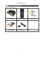
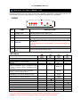
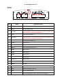
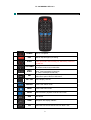
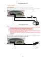
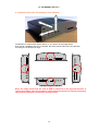
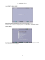
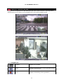
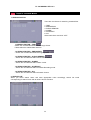
F1-110 MANUAL VER 1.0.3 H.264 2-Channel DVR F1-110 / F1-110G User’s Manual ▪ H.264 2Ch. DVR ▪ Built-in GPS (F1-110G Model) ▪ 3-Axis Shock Sensor ▪ Up to 32G SDHC ※ The contents of the manual can be modified without prior notice to customers 1 F1-110 MANUAL VER 1.0.3 GENERAL SAFETY AND PRECAUTIONS F1-110 is manufactured to meet international safety standards. Read the following safety precautions to avoid injury and prevent damage to the F1-110 or any products connected to it. 1. Use a correct power source. Do not connect this product to a power source that supplies more than the specified voltage (DC12V), as this will cause damage to the unit. 2. Never insert anything metallic into F1-110 as this can cause electric shock. 3. Do not operate in wet & dusty conditions. Keep product surfaces clean and dry. Avoid placing the F1-110 in areas like a damp basement or a dusty hallway. 4. Do not expose this product to rain or use near water. If the product gets wet, unplug it and contact an authorized dealer immediately. 5. To clean the outside case of the F1-110, use a lightly dampened cloth (no solvents). 6. Do not operate if you suspected unit is faulty. If there are any unusual sounds or smells coming from the F1-110, immediately unplug it and contact an authorized dealer or service centre. 7. Do not attempt to remove the top cover. Warning: Removing the DVR’s cover can cause an electrical shock. 8. Handle F1-110 carefully to avoid damaging the product. Dropping your F1-110 on any hard surface may cause the unit to malfunction. If the F1-110 does not work properly due to physical damage, contact an authorized dealer for repair or exchange. 9. The unit has a lithium battery preinstalled. The standard lithium cell 3V battery located on the motherboard should be replaced if the time clock does not hold its time after the power is turned off. Warning: Unplug the F1-110 before replacing battery or you may be subjected to severe electrical shock. Properly dispose of old batteries. Caution: Risk of explosion if battery is replaced by an incorrect type. Do not discard lithium batteries into the trash can or into fire. Dispose in accordance with local waste regulations. 2 F1-110 MANUAL VER 1.0.3 TABLE OF CONTENTS CHAPTER 1: PACKING CONTENTS 5 CONTENTS IN THE PACKAGE CHAPTER 2: GETTING TO KNOW F1-110 6 F1-110 CHAPTER 3: REMOTE CONTROL 8 REMOTE CONTROL BUTTON CHAPTER 4: GETTING STARTED 10 HOW TO INSTALL F1-110 CHAPTER 5: HARDWARE INSTALLATION 1. FORMAT SD MEMORY CARD 11 2. INSERT SD MEMORY CARD 11 3. BACKUP RECORDED FILES 11 4. CONNECTING F1-110 TO YOUR TV SET OR MONITOR 11 5. INSTALL IN THE VEHICLE 5.1 PARKING MODE 5.2 NORMAL MODE 6. INSTALLATION DIRECTION ACCORDING TO SHOCK SENSOR 13 14 CHAPTER 6: MENU MODE MENU TREE 15 1. ACCESS TO MENU MODE 16 2. MAIN MENU 16 3. SYSTEM SETUP 3.1 TIME SET > DAY LIGHT SAVING 3.2 Day Light Saving 3.3 TIME OVERLAY 3.4 TIME CORRECTION 3.4.1 HOW TO SETUP TIME CORRECTION 3.5 LANGUAGE SETUP 3.6 VIDEO OUTPUT 3.7 GPS 17 4. A/V SETUP 4.1 RESOLUTION 4.2 VIDEO QUALITY 4.3 FRAME RATE 4.4 BRIGHTNESS 4.5 AUDIO INPUT LEVEL 4.6 REMAINING MEMORY 4.7 CHANNEL SELECT 4.8 PIP 18 3 F1-110 MANUAL VER 1.0.3 5. RECORDING SETUP 5.1 CONTINUOUS RECORDING 5.2 RECORDING BLOCK 5.3 POST-RECORDING TIME 5.4 DISK OVERWRITE 19 6. EVENT SETUP 6.1 SHOCK SENSOR SENSITIVITY 6.2 ALARM INPUT 6.2.1 ALARM CONTINUE 6.3 ALARM OUTPUT 6.4 SCHEDULE SETUP 6.4.1 TIME 6.4.2 EVENT 20 7. RS-485 7.1 RS-485 7.2 RS-485 ID 7.3 RS-485 ID OVERLAY 7.4 BAUDRATE 7.5 PROTOCOL 7.6 KEYBOARD MAPPING 21 8. SUB MENU 8.1 PASSWORD ENABLE 8.1.1 CURRENT PASSWORD 8.1.2 NEW PASSWORD 8.1.3 CONFIRM PASSWORD 8.2 FIRMWARAE UPDATE 8.3 SYSTEM INFORMATION 22 CHAPTER 7: NAVIGATION BAR 23 1. SCREEN ICON CHAPTER 8: SEARCH MODE 1. SEARCH FACTOR 1.1 SEARCH FACTOR-TIME 1.2 SEARCH FACTOR-EMERGENCY 1.3 SEARCH FACTOR-SHOCK SENSOR 1.4 SEARCH FACTOR-ALARM 1.5 SEARCH FACTOR-SCHEDULE 1.6 SEARCH FACTOR-ALL 26 2. SEARCH LIST Appendix: 27 TECHNICAL SPECIFICATIONS 4 F1-110 MANUAL VER 1.0.3 CHAPTER 1: PACKING CONTENTS ▶ Contents in the package F1-110 Unit REMOTE CONTROL WIRE HARNESS GPS ANTENNA (F1-110G Only) 5 INSTALL CD F1-110 MANUAL VER 1.0.3 CHAPTER 2: GETTING TO KNOW F1-110 This chapter briefly describes the functions of each button on F1-110. The buttons are used to operate the basic functions of F1-110, such as recording, playback, fast-forward, reverse play and etc. For more details on the set-up and operation of F1-110, refer to Chapter 6, F1-110 MENU. FRONT ⑤ ①② ③④ NO ITEM ⑥ DESCRIPTION 1 POWER LED Red LED lights on when power is on. 2 REC LED Green LED lights on while recording. 3 FAULT LED Yellow LED blinks when error occurs. 4 GPS LED Blue LED blinks while finding GPS signal and lights on when GPS * is in 3D fix . * 3D fix requires four or more satellites, and provides latitude and longitude. 5 IR Receiver Point remote control at the IR receiver. 6 SD MEMORY CARD Slot Insert or take out SD memory card. LED Status Status Standby Status on Parking Mode Normal Mode Wakeup Status on Parking Mode Booting Recording Error 5Blink ◑ ON 1Blink ◑ ON (INSERT SD MEMORY CARD / SD MEMORY CARD LOCKED / SD INVALID FORMAT / SD MEMORY CARD FULL / ETC.) ON ON Normal ◑ System Error Slow ◑ (INVALID FILE / FILE NOT FOUND / OSD LOAD ERROR / VIDEO DECODER ERROR) Memory Error Fast ◑ (SD MEMORY CARD ERROR / MEMORY ERROR) System Fault ON (IRRECOVERABLE HARDWARE ERROR) ON On Recording SD Eject GPS Not Used / No GPS Data GPS 3D Fix Level 0 / GPS not in 3D Fix GPS 3D Fix Level 1 GPS 3D Fix Level 2 GPS 3D Fix Level 3 Slow ◑ OFF Slow ◑ Normal ◑ Fast ◑ ON ※ LED Status ● On / Off / Normal: blink 500msec, Fast: blink 100msec, Slow: Blink 1sec (Interval) ● 5Blink: 5sec Off 0.3sec On (repeat) / 1Blink: 1sec Off 0.3sec On (repeat) 6 F1-110 MANUAL VER 1.0.3 REAR S A B CD EF G H I J K L M NOPQ R T NO ITEM DESCRIPTION A 12V DC 12V Input B BATT 12V Car Battery Input C DC OUT1 DC Output for Camera1 (The maximum current consumption and input voltage of the camera connected should be considered) D V-IN1 Video Input for Camera 1 E DC OUT2 DC Output for Camera 2 (The maximum current consumption and input voltage of the camera connected should be considered) F V-IN2 Video Input for Camera 2 G V-OUT Video Output H A-OUT Audio Output I MIC1/2 Audio Input (Microphone) 1/2 J ALM1 Alarm Input 1 K ALM2 Alarm Input 2 L ALM3 Alarm Input 3 M ALM4 Alarm Input 4 N ALM OUT Alarm Output O RS485+ RS-485 + P RS485- RS-485 - Q PWR-CN External Power On/Off R REC External Emergency Record S GPS Connect GPS Antenna T RESET System Rebooting (※ Option values are not changed) 7 F1-110 MANUAL VER 1.0.3 CHAPTER 3: REMOTE CONTROL POWER REC EJECT UP/ DOWN LEFT/ RIGHT ENT Turn on / off power. Start or stop emergency recording. Stop recording and turn off SD memory card power. Press eject button before taking out SD memory card from the SD slot. Change values on OSD menu On search mode, find recorded files Change values on OSD menu REW : Fast Rewind(X2-X4-X8-X16) FF: Fast Forward(X2-X4-X8-X16) On playback mode, playback at X1 or pause. Select each option value on OSD menu. CH1/ CH2 Select display channel. SEARCH Enter & exit search mode. MENU Enter & exit menu mode. MODE Switch between playback mode and live mode. GPS GPS Reset VIEW Navigation bar display ON/OFF PIP Select the size of sub channel: PIP off / QCIF / CIF 8 F1-110 MANUAL VER 1.0.3 REW PAUSE/ PLAYBACK FF 0-9 Fast rewind (X2-X4-X8-X16) ※ Shows only I-frame of the recorded file being played. Pause & playback recorded file at X1. Fast forward (X2-X4-X8-X16) ※ Shows only I-frame of the recorded file being played. STOP Stop playback (Display the first frame of the playback file). MUTE Remove Audio during playback NUMBER Enter number key when setting up time and etc. on OSD menu. 9 F1-110 MANUAL VER 1.0.3 CHAPTER 4: GETTING STARTED HOW TO INSTALL F1-110 Below is an overview of the F1-110 installation procedures (For more detail please refer to Chapter 5 - Hardware Installation.). (1) (2) (3) (4) (5) (6) Insert a SD memory card into the SD slot. Connect F1-110 to a TV set or monitor. Connect camera to F1-110 Connect optional accessories (sensors and alarm-out device) Connect the power input. Start monitoring and recording. General Operating Advice: Make sure that a SD memory card is inserted and two cameras are properly connected. (Refer to Chapter 5 -Hardware Installation) The SD memory card must be formatted (Refer to Chapter 5 – SD Memory card Installation.) Otherwise, F1-110 may not recognize the SD Memory. F1-110 offers you the flexibility to choose a recording frame rate (maximum rate: 30fps / NTSC, 25fps / PAL). The faster the frame rate is, more natural video image output appears from recorded files. However, it requires more SD memory card capacity. You may reduce the frame rate (minimum rate: 1 frame per second) to fit longer recording sessions in consideration of your SD memory card capacity. The default values of F1-110 for recording are set up at 30fps (Camera 1)/10fps (Camera 2) with High video quality. If shock sensor is triggered while car is parked, F1-110 wakes up on ‘parking mode’ and records accordingly. If NTSC and PAL cameras are connected together, F1-110 recognizes this as ‘video loss’. 10 F1-110 MANUAL VER 1.0.3 CHAPTER 5: HARDWARE INSTALLATION SD memory INSTALLATION 1. Format SD memory card Insert SD memory card into SD slot in your PC and format it ※ Be sure to format SD memory card in FAT32 or FAT16. 32KB is highly recommended as the default allocation size. ※ If your PC does not have SD slot, use SD memory card reader. ※ Timely formatting the SD memory card and backup the files in it are required to avoid SD memory card error and file loss. ※ Use the original SD memory card only. If not, data loss may happen. It is recommended to use original SanDisk SD memory card. 2. Insert SD memory card into the SD slot in F1-110 After formatting, take out SD memory card from your PC and insert it into SD slot on F1-110. When taking out SD memory card from F1-110 slot, you should press eject button for 1~2 seconds on the remote control. ※ Pressing eject button shut the power to SD slot. This status lasts for 3 minutes and is deactivated automatically after 3 minutes. This is deactivated before 3 minutes on the following status; Mode change (Live Playback) / Emergency Recording / Removing SD memory card) 3. Backup recorded files in SD memory card When SD Memory card capacity is full, the recorded files can be backed up in your PC. Insert SD memory card in your PC and move the files in the HDD of your PC. You can also check each recorded file through viewer software. 4. Connecting F1-110 to TV or monitor ① Video Input/Output 11 F1-110 MANUAL VER 1.0.3 To display images from F1-110, connect the video output port to monitor or TV with appropriate video cable. Any TV with a video input terminal is suitable for displaying the images. The diagram above shows the video signal connections. Connect the camera to video-in terminal of AV-IN connector; connect the monitor to video-out terminal of AV-OUT connector. Note: RCA cable required for this connection is not provided with F1-110 ② Audio Input/Output Connection (For TV / monitor speaker) Connect a microphone to audio-in terminal of AV-IN connector and connect the speaker to audioout terminal of AV-OUT connector. ③ GPS Connection GPS antenna (F1-110G model) should be connected additionally when you want to use GPS function. Antenna must be placed toward the direction of the sky so that it receives GPS signal well from GPS satellites. F1-110 cannot receive GPS signal well it is placed in the confined spaces such as ‘among tall buildings’ and ‘in tunnels’. It may take long time for F1-110 to receive GPS signal when it is left in ‘power-off’ condition for long term. When it does not find GPS signal, check if the current position is shaded area and reset GPS by pressing GPS button on remote control. Note: GPS signal reception failure may occur under the following conditions. 1) An object is placed on the antenna. 2) Windshield is tinted in metal constituent. 3) Install electric device that generates electromagnetic interfering GPS signal inside of vehicle. ex) Remote Start System 4) Cloudy weather 5) Confined spaces; in tunnel, under overpass, in underpass, in underground parking lot, among tall buildings and etc. ※ Electrical device near GPS antenna can interfere GPS data reception. Be sure to place GPS antenna to the appropriate position. 12 F1-110 MANUAL VER 1.0.3 5. Install in Vehicle 5.1 Parking Mode When a power cable is connected to car battery, parking mode is supported. While parked with car engine off, F1-110 is not entirely off on parking mode. F1-110 consumes minimum power (standby), wake up by shock sensor trigger and starts recording. Fuse On/Off Switch (5A) [Vehicle Battery Connection] Note: 1) When the car battery voltage goes down below 12V for 3 minutes, F1-110 is cut off from the power automatically for battery discharge protection. 2) F1-110 on standby wakes up by shock sensor sensitivity level 5. 3) The recorded video is according to the AV setup on OSD menu. 4) Video is recorded in 1fps regardless of AV setup values until SD memory card is initialized on wakeup status of ‘parking mode’. This initialization may take 2 ~ 10 seconds according to SD memory card capacity and kinds. 5.2 Normal Mode On normal Mode, F1-110 performs recording only when car engine is on. Connect F-110 power to the cigar jack in the vehicle with appropriate cigar jack cable. Cigar Jack Cable 13 F1-110 MANUAL VER 1.0.3 6. Installation Direction According to Shock Sensor Z X Y The direction of 3 axis shock sensor data (x, y, z) is shown as the image above. Even though installation direction is changed, the shock sensor finds new 3 axis direction according to new direction change. Note: The image shows that the front of DVR is positioned in the opposite direction of vehicle proceeding. If the front of DVR is positioned in the direction of vehicle proceeding, shock sensor data does not stand for accurate values. 14 F1-110 MANUAL VER 1.0.3 CHAPTER 6: MENU MODE MENU TREE TIME SET▷ DAY LIGHT SAVING▷ TIME OVERLAY SYSTEM SETUP▷ TIME CORRECTION LANGUAGE VIDEO OUTPUT GPS RESOLUTION VIDEO QUALITY FRAME RATE A/V SETUP▷ BRIGHTNESS AUDIO INPUT LEVEL REMAINING MEMORY DISPLAY CHANNEL PIP CONTINUOUS RECORDING RECORDING SETUP ▷ RECORDING BLOCK POST RECORDING TIME DISK OVERWRITE MENU▷ SHOCK SENSOR SENSIBILITY ALARM INPUT▷ EVENT SETUP ▷ ALARM OUTPUT SCHEDULE SETUP▷ RS-485 RS-485 ID RS-485 ▷ RS-485 ID OVERLAY BAUDRATE PROTOCOL PASSWORD ENABLE CURRENT PASSWORD: NEW PASSWORD CONFIRM PASSWORD FW UPDATE SUB MENU▷ SYSTEM INFORMATION▷ Assigned Code SW Version HW Version 15 F1-110 MANUAL VER 1.0.3 1. ACCESS TO MENU MODE Press ‘MENU’ button on remote control to access to F1-110 menu mode. Please refer to ‘Chapter 3: Remote control’ about how to use remote control buttons. Password is ‘0000’ as default. To change the password, go to SUB MENU -> PASSWORD ENABLE. 2. MAIN MENU On the main menu, when you select each menu by using up and down arrow key on the remote control, selected menu item is highlighted. 16 F1-110 MANUAL VER 1.0.3 3. SYSTEM SETUP 3.1 TIME SET Set up current local time. 3.2 DAY LIGHT SAVING: Select ‘ON’ when you want to apply ’Day Light Saving’. Set up specific period when ‘Day Light Saving’ is applied. 3.3 TIME OVERLAY Select ‘OFF’ when you don’t want ‘Time and Date’ stamp on the screen on LIVE Mode or Playback Mode. 3.4 TIME CORRECTION: Where there is discrepancy between F1-110 time and actual time, user can correct the discrepant time. - Time: -999 sec (F1-110 time is ahead of actual time) ~ +999 sec (F1-110 time is behind the actual time) - Correction Cycle: Select correction cycle among Day / Week / Month. ※ ‘Time Correction’ is disabled when GPS is set to ‘ON’. 3.4.1 How to Setup Time Correction ① Find the time error: Check how much difference occurs between F1-110 time and actual time. ② Re-setup the time of F1-110 to current time. ③ Enter correction time and cycle. - When F1-110 time is ahead of actual time: Insert minus value by pressing arrow or number key. - When F1-110 time is behind the actual time: Insert plus value by pressing arrow or number key. [Example] Start time to get time error: 2010/07/05 12:00:00 Finish time to get time error: 2010/07/12 12:00:00 TIME Error : 2010/07/12 12:01:00 Error for 7 days: +60sec Time Setting: 2010/07/12 12:00:00 Time Correction: -060sec / Week When time correction is applied: 2010/07/19 12:00:00 ※ Time correction is not applied on recording even when correction time comes. On ‘emergency recording’, recording block generates by 3, 5 or 10 minutes. Time correction is applied when recording block closes on recording. 17 F1-110 MANUAL VER 1.0.3 3.5 LANGUAGE SETUP Select between English and Japanese 3.6 VIDEO OUTPUT Display NTSC or PAL according to unit’s CCD type 3.7 GPS Select ‘ON’ when users want to use GPS function by connection external GPS antenna (F1110G Model) F1-110 renews its time system by GPS. (plus or minus 3 second error) ※ Coordinated Universal Time (abbreviated UTC) is the primary time standard by which the world regulates clocks and time. 4. A/V SETUP 4.1 RESOLUTION Resolution 4CIF CIF NTSC PAL 704 x 480 352 x 240 704 x 576 352 X 288 4.2 VIDEO QUALITY (HIGHEST / HIGH / NORMAL / LOW / LOWEST): Select desired video level 4.3 FRAME RATE NTSC: Selectable among 30(10), 15, 10, 3, 1 PAL: Selectable among 25(8), 12, 8, 3, 1 * Example NTSC FRAME RATE - CHANEL 1: CHANEL 2: PAL FRAME RATE - 30 10 15 10 3 1 10 30 15 10 3 1 12 8 3 1 12 8 3 1 CHANEL 1: 25 8 CHANEL 2: 8 25 4.4 BRIGHTNESS 18 F1-110 MANUAL VER 1.0.3 Select camera brightness value among low, normal and high. 4.5 AUDIO INPUT LEVEL User can select from ‘0’ to ‘10’ according to microphone input level. (Default Value: 7) - 0: Audio Recording Off - 1: lowering microphone level - 10: Increasing microphone level 4.6 REMAINING MEMORY Shows total memory and usable memory including possible recording time. 4.7 CHANNEL SELECT Setup the display channel for 1 CH/2 CH 4.8 PIP You can select sub channel size as below. (Default Value: QCIF) - QCIF (NTSC: 176 X 120, PAL: 176 X 144) - CIF (NTSC: 352 X 240, PAL: 352 X 288) - PIP OFF 5. RECORDING SETUP 5.1 CONTINUOUS RECORDING Recording continues as long as SD memory card is available. 5.2 RECORDING BLOCK File recorded in terms of 3/5/10 min - Default Value: 5 min ※ Regardless of recording block, the number of files is limited to 5,000. 5.3 POST RECORDING TIME Post recording time defines how long you will record after an event occurs. - Default Value: 20 sec - Range: Min 5 sec ~ Max 180 sec 5.4 DISK OVERWRITE Disk Overwrite On: When SD memory card capacity is full, F1-110 deletes the file in the order of early recording time and keeps recording with over-writing. Disk Overwrite Off: Recording stops when the SD memory card capacity is full. 19 F1-110 MANUAL VER 1.0.3 6. EVENT SETUP 6.1 SHOCK SENSOR SENSITIVITY Setup the shock sensor sensitivity. (Range: off, 1 ~ 5) - Default Value: 3 (5: Sensitivity High, 1 / Sensitivity Low) - F1-110 on standby mode wakes up and starts to record by shock sensor sensitivity level 5. 6.2 ALARM INPUT: Setup ALARM INPUT NO / NC / Off Select 'NO' or ‘NC’ according to sensor type for ALARM EVENT RECORDING. For Alarm Recording, user can setup up to 4 alarms. 6.2.1 Alarm Continue Select between ‘Continue On’ and ‘Continue Off’. When selecting ‘on’, recording continues until event stops regardless of post recording time. 6.3 ALARM OUTPUT ALARM INPUT ALARM OUTPUT Normal Open Normal Open Alarm input type is Normal Open. The device connected to alarm output is in ‘OFF ‘status and turns ON when events occur. Normal Open Normal Close Alarm input type is Normal Open. The device connected to alarm output is in ‘ON ‘status and turns OFF when events occur. Normal Close Normal Open Alarm input type is Normal Close. The device connected to alarm output is in ‘OFF ‘status and turns ON when events occur. Normal Close Normal Close Alarm input type is Normal Close. The device connected to alarm output is in ‘ON ‘status and turns OFF when events occur. ※ Alarm-Out is also activated when shock sensor is detected on standby status of parking mode. 6.4 SCHEDULE SETUP Setup time for Schedule Recording (Up to 4 different time settings possible) 6.4.1 TIME: Start to record when scheduled time is up. 6.4.2 EVENT: to record when event (triggered by alarm-in device or shock sensor) occurs during scheduled period. ※ Pre-recording time is 5 seconds. F1-110 starts to record 5 seconds before actual event time. 20 F1-110 MANUAL VER 1.0.3 7. RS-485 7.1 RS-485 Select ‘Yes’ when users want to control F1-110 by keyboard controller. 7.2 RS-485 ID Assign 3-digit number to F1-110. Default ID is ‘000’. (0 ~255) 7.3 RS-485 ID Overlay Select ‘Yes’ when users want to stamp RS-485-ID on video data and show it on the display on playback. 7.4 Baud Rate Select from 1200/ 2400/ 4800/ 9600/ 19200/ 38400 according to your keyboard control you wish to connect. 7.5 Protocol Select between PELCO-D and PELCO-P according to our keyboard control you wish to connect. 7.6 Keyboard Mapping Key REC ENT SEARCH UP/DOWN ARROW REW Play / Pause CH2 Power Off VIEW STOP Function Iris Open Zoom In Focus Near Tilt Up / Tilt Down Pan Left Zoom In / Zoom Out 2 + Preset 200 + Preset 202 + Preset 204 + Preset 21 Key EJECT MENU MODE RIGHT/LEFT ARROW FF CH1 0~9 GPS PIP MUTE Function Iris Close Zoom Out Focus Far Pan Right / Left Pan Right 1 + Preset 100~109 + Preset 201 + Preset 203 + Preset 205 + Preset F1-110 MANUAL VER 1.0.3 8. SUB MENU 8.1 PASSWORD ENABLE Select ‘Yes’ means you should enter password when you access to menu mode. The factory default value is ‘0000’. Press the number button on the remote control to enter the new password & change the password. 8.1.1 CURRENT PASSWORD: Displays current Password 8.1.2 NEW PASSWORD: Input new Password 8.1.3 CONFIRM PASSWORD: Re-type the new Password for confirmation 8.2 FW UPDATE Update the F1-110 to latest F/W 8.3 SYSTEM INFORMATION Displays F1-110’s system information: - Assigned Code : Display assigned code - SW Version : Displays current SW version - HW Version : Displays current HW version 22 F1-110 MANUAL VER 1.0.3 CHAPTER 7: NAVIGATION BAR Navigation bar is displayed on the top and bottom part of the screen as shown in the image below. Various screen icons is shown on the navigation bar on live mode or playback mode. [Navigation Bar on Playback Mode] [Navigation Bar on Live Mode] 1. SCREEN ICON Live Mode Displays on Live mode Record Displays on Recording but no file is generated until the icon color turns into red. Record Displays on Recording. A file is generated. 23 F1-110 MANUAL VER 1.0.3 Playback Displays on Playback mode Menu Displays when entering Menu Mode Search Displays on entering Search mode Disk Overwrite On / Off Overwrite On: Orange / Overwrite Off: grey Remaining Size Displays the remaining size for recording Current Time Displays the current time Day Light Saving When day light saving mode is applied SD MEMORY CARD Exist Displays when SD MEMORY CARD is inserted SD MEMORY CARD LOCK Displays when SD MEMORY CARD is locked SD MEMORY CARD FULL Warning Displays when SD MEMORY CARD is almost full regardless of overwrite setup. ※Shows when SD memory card has 1 hour recording capacity. SD MEMORY CARD INITIALIZING Displays when SD MEMORY CARD is initializing. Invalid SD MEMORY CARD/ SD MEMORY CARD Error Displays when SD MEMORY CARD is invalid or SD MEMORY CARD error occurs SD MEMORY CARD FULL Displays when SD MEMORY CARD is full ※Shows only when ‘overwrite’ is set to ‘on’. No SD MEMORY CARD Displays when there is no SD MEMORY CARD. GPS Not in 3D Fix 3D Fix Level 0 6.0 < HDOP (Horizontal Dilution of Precision) 3D Fix Level 1 4.0 < HDOP < 6.0 3D Fix Level 2 2.0 < HDOP < 4.0 3D Fix Level 3 HDOP < 2.0 Supercap Displays when F1-110 power is connected to DC. green: Supercap charged / grey: Supercap Discharged Wakeup Displays on wakeup status of parking mode. CH1 Displays Channel 1 Status yellow: Camera 1 connected / grey: not connected 24 F1-110 MANUAL VER 1.0.3 CH2 Displays Channel 2 Status yellow: Camera 2 connected / grey: not connected Main CH1 or Main CH2 Displays main channel Resolution Displays the current resolution. Recording Displays always on continuous recording Emergency Recording Displays on Emergency recording mode Shock Sensor Recording Displays on recording triggered by shock sensor Alarm Recording Displays on recording triggered by alarm input device Schedule Recording Displays on Schedule Recording mode Rewind Displays when rewinding the recorded files Fast Forward Displays when fast-forward the recorded files Playback Displays when playback the recorded files Stop Displays when stop the playing back the recorded files Pause Displays when pause the playback the recorded files Sound Displays when sound is On or Off on playback mode Sound is off on rewind or fast forward playback. 25 F1-110 MANUAL VER 1.0.3 Chapter 8: SEARCH MODE 1. SEARCH FACTOR There are nine factors for searching recorded files. 1. TIME 2. EMERGENCY 3. SHOCK SENSOR 4. ALARM 5. SCHEDULE 6. ALL Select each factor and click “LIST” 1.1SEARCH FACTOR – TIME: Search the recorded files within certain range of time. Please select the wanted date and time. 1.2 SEARCH FACTOR – EMERGENCY : Search the recorded files within Emergency Mode. 1.3 SEARCH FACTOR – SHOCK SENSOR : Search the recorded files within Shock Sensor Mode. 1.4 SEARCH FACTOR – ALARM : Search the recorded files within Alarm 1/2/3/4. 1.5 SEARCH FACTOR – SCHEDULE : Search the recorded files within Schedule Recording mode. 1.6 SEARCH FACTOR – ALL : Search the recorded files within all search factors. 2. SEARCH LIST When you select search factor and enter appropriate value accordingly, search list result corresponding to search factor and its value is shown as below. 26 F1-110 MANUAL VER 1.0.3 APPENDIX TECHNICAL SPECIFICATION ITEM DESCRIPTION VIDEO Input Channel 2 CHANNEL Input impedance 75 ohm Unbalanced Input Format PAL/NTSC (Auto Detection), Composite Maximum Input 1.0Vp-p @ 75 Ohm Unbalanced Output Channel 1 Ch.(PIP Support) Output impedance 75 ohm Unbalanced Output Format Maximum Output Deinterlace PAL/NTSC (according to Input), Composite 1.0Vp-p @ 75 Ohm Unbalanced Perform high quality deinterlacing for arbitrary format of interlaced video input RECORDING Encoding H.264 File Format SFR (Proprietary Format) Video Recording Resolution Format PAL NTSC 4CIF 704x576 704x480 CIF 352x288 352x240 Video Recording Quality Qulity Highest High Normal Low Lowest 4CIF (kbps) 1700 1700 1500 1200 1100 CIF (kbps) 1400 1400 1100 900 650 Video Recording Frame Rate Recording MODE Decoding Video Format Pre-recording Time Storage NTSC 30/10, 15/15, 10/10, 3/3, 1/1 fps PAL 25/8, 12/12, 8/8, 3/3, 1/1 fps Continuous Recording / Emergency / Schedule / Alarm / ShockSensor As recorded Quality & Frame Rate Max. 5sec@Normal Mode Recording Support SD, SDHC(2~32GB, More than Class4 ) Storage File System FAT16, FAT32(recommended) Allocation Unit Size` 32Kbytes(recommended) @2GB-32GB SD/SDHC Maximum Recording File 5,000 files AUDIO Compression Format 8KHz, 16bit Mono PCM Input Channel 2 Ch. Mono Input impedance 4.7K ohm typ. Maximum Input 1.2 Vp_p @ Audio Input Level 1(Menu) Output Channel 1 Ch. Mono, Unbalanced Maximum Output 13mW@RL =16ohm, Unbalanced ALARM 27 F1-110 MANUAL VER 1.0.3 Input Output 4 Ch. TTL(Internal pull-up), 40V max. 1 Ch. TTL(Open Drain), 15V max. 500mA max. OPERATING MODE Operating Mode Normal Mode: Live/Playback/Menu/Search/Record Parking Mode: Record Only VIEWER SOFTWARE Monitoring Environment Client S/W File Convert AVI(Audio video interleaving) I/O Power 28pin Pluggable Header Connector (Video out 1CH, MIC in 2CH, Speaker out 1CH, Alarm in 4CH, Alarm out 1CH, RS485, Emergency REC, Power Control) 8pin Pluggable Header Connector (Video input 2CH, Camera power output 2CH) 4pin Pluggable Header Connector (DC input, Battery input) SD Slot 1Port, SD Card Slot I/O Camera OTHERS LED 4 Status LED (Power, REC, Fault, GPS) Remote Control 1 IR Receiver Shock Sensor 3-Axis Shock Detection POWER Input Voltage Range Power Consumption Camera Power Output Main(DC): 10 to 15VDC(@9.5VDC Cut off) Battery: 12 to 15VDC (@12VDC Cut off) Normal Mode: Approx. 300mA @ 12VDC (750mA max. initial peak current @ 12VDC ) Standby Status on Parking Mode: Approx. 6mA @ 12VDC Input power bypass @ 10 to 15VDC, 900mA max. Power is supplied to camera only on normal and wakeup mode. ※ Caution: Be sure to check camera input voltage range(before connection) ENVIRONMENTAL Operating Temperature -20 ~ +60 °C Humidity 30 ~ 80 %RH (non-condensing) PHYSICAL Dimension 120(W) x 78(L) x 29.5(H) mm Weight Approx.205g ACCESSORY Remote Control Supplied SD Memory Card Option GPS Antenna F1-110G Model Only I/O Wire Harness Supplied(Receptacle to wire) Camera Wire Harness Supplied(Receptacle to wire) Power Wire Harness Supplied(Receptacle to wire) 28