1
RTX 1000A Series
Analog Pressure Transmitter
User manual
Druck Incorporated, 4 Dunham Drive, New Fairfield, Connecticut 06812, U.S.A.
Telephone: +1 203 746 0400 Facsimile: +1 203 746 2494
KA332
Approved Service Agents
Trademarks
All product names are trademarks of their respective companies.
USA
HOLLAND
Druck Incorporated, 4 Dunham Drive,
New Fairfield, Connecticut 06812,
USA.
Druck Nederland bv, Zuideinde 37,
2991 LJ Barendrecht,
The Netherlands.
Tel: +1 203 746 0400
Fax : +1 203 746 2494
Tel: +31 (0)1806 11555
Fax : +31 (0)1806 18131
BRAZIL
ITALY
Druck Brasil Ltda.
Rua 9 de Julho, 25 - Térreo,
São Bernardo do Campo - SP
CEP 09606-010, Brazil.
Druck Italia Srl., Via Magenta 77,
edificio 5, 20017 Rho (Milano),
Italy.
Tel: +55 (0)11 4367 3477
Fax: +55 (0)11 4368 9686
Tel: +39 (0)2 93 20 61
Fax : +39 (0)2 93 20 62 99
FRANCE
JAPAN
Druck SA, 19 rue Maurice Pellerin,
92600 Asnières,
France.
Druck Japan KK, Medie Corp
Building 8, 2-4-14 Kichijoji-Honcho,
Musashino, Tokyo 180-0004, Japan.
Tel: +33 (0)1 41 32 34 64
Fax: +33 (0)1 47 93 00 48
Tel: +81 (0)422 20 7123
Fax: +81 (0)422 20 7155
GERMANY
UK
Druck Messtechnik GmbH,
Auf dem Hohenstein 7,
61231 Bad Nauheim, Germany.
Druck Ltd., Fir Tree Lane, Groby,
Leicester, LE6 0FH,
England.
Tel: +49 (0)6032 93300
Fax: +49 (0)6032 933080
Tel: +44 (0)116 231 7100
Fax: +44 (0)116 231 7103
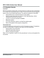
RTX 1000A Series User Manual
Safety
To use this equipment safely, you must use the data and procedures in these
publications:
•
The "Calibration data and instructions" for the equipment
•
The applicable CSA or FM Approvals 'Control Drawing'
(Hazardous or Classified areas only)
•
This user manual
These publications contain instructions to operate the equipment and maintain it
in a safe condition. To prevent damage or injury:
•
Obey all warnings and cautions
•
Use the equipment only for the specified applications
•
Operate the equipment only in the specified limits.
To install and use the equipment, use only approved engineers who have the
necessary skills and qualifications.
Hazardous (Classified) areas
Some versions of this equipment are certified for use in hazardous (classified)
areas. For these versions, GE Druck supplies 'Control Drawings' with additional
installation data. The 'Control Drawings' are:
•
CSA 'Control Drawing' - KA337
•
FM Approvals 'Control Drawing' - KA253
i
KA332 Issue No. 1
RTX 1000A Series User Manual
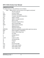
ABBREVIATIONS
The abbreviations in this publication are as follows:
Note: Abbreviations are the same in the singular and plural.
a
absolute pressure
A/D
analog to digital
AWG
American wire gauge
CSA
Canadian Standards Association
D/A
digital to analog
DAC
digital to analog convertor
DC
direct current
DIN
Deutsche Industrie Norm
DIP
dual inline package
DPM
digital pressure module
°C
degrees Celsius
°F
degrees Fahrenheit
EEPROM
electrically erasable programmable read-only memory
EMC
electromagnetic compatibility
FM
Factory Mutual Approvals
FS
full-scale
g
gauge pressure
in
inch (")
inH2O
inches of water
IS
intrinsically safe
kg
kilogram
lb
pound
lbf.ft
pound-force feet
LCD
liquid crystal display
LDV
lower display value
LRV
lower range value
KA332 Issue No. 1
ii
RTX 1000A Series User Manual
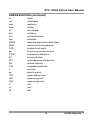
ABBREVIATIONS (continued)
m
mA
max
mbar
µF
mH
min
mm
MSDS
MWP
PCB
psi
PTFE
PV
RFI
RH
RTX
s
sg
UDV
URL
URV
V
Ω
W
meter
milliampere
maximum
millibar
microfarads
millihenry
minimum/minute
millimeter
materials specification data sheet
maximum working pressure
printed circuit board
pound-force per square inch
polytetrafluoroethylene
primary variable
radio frequency interference
relative humidity
rangeable transmitter
seconds
specific gravity
upper display value
upper range limit
upper range value
volt
ohm
watt
iii
KA332 Issue No. 1
RTX 1000A Series User Manual
CONTENTS
Section
title
page
Safety .....................................................................
ABBREVIATIONS ...................................................
CONTENTS ...........................................................
i
ii
iv
1
1.1
1.2
1.3
DESCRIPTION .......................................................
Introduction ............................................................
About the Electronics Housing ...............................
Identification Codes ................................................
1-1
1-1
1-1
1-3
2
2.1
2.2
2.3
2.4
TECHNICAL DATA ................................................
Pressure Ranges ...................................................
Environment Data ...................................................
Performance Data ..................................................
Physical Data .........................................................
2-1
2-1
2-1
2-1
2-4
3
3.1
3.2
3.3
3.4
3.5
3.6
3.7
3.8
3.9
3.10
INSTALLATION .....................................................
Introduction ............................................................
Special Tools and Equipment .................................
Location and Mounting ...........................................
To Rotate the Display Thru 90° ...............................
To Rotate the Housing ............................................
Impulse Piping ........................................................
The Transmitter Pressure Connections ...................
Liquid Level Measurement ......................................
Electrical Data ........................................................
System Checks ......................................................
3-1
3-1
3-1
3-2
3-2
3-3
3-3
3-4
3-6
3-7
3-10
KA332 Issue No. 1
iv
RTX 1000A Series User Manual
CONTENTS (continued)
4
4.1
4.2
4.3
4.4
OPERATION ..........................................................
General ..................................................................
Manual Configuration Facilities ...............................
Manual Configuration - LCD Operation ...................
Manual Configuration - Calibration .........................
4-1
4-1
4-2
4-3
4-4
5
5.1
5.2
5.3
Maintenance .........................................................
General ..................................................................
Fault Finding ...........................................................
Returned Goods Procedure ...................................
Safety Precautions .................................................
Important Notice .....................................................
5-1
5-1
5-2
5-3
5-3
5-3
Approved Service Agents ...................................... Back cover
v
KA332 Issue No. 1
RTX 1000A Series User Manual
ILLUSTRATIONS
Figure
title
page
1-1
1-2
General view .......................................................... 1-1
Transmitter schematic diagram ............................... 1-2
2-1
2-2
2-3
Range limits ........................................................... 2-1
Dimensions (Transmitter) ....................................... 2-4
Dimensions (Optional mounting bracket) ................ 2-5
3-1
3-2
3-3
3-4
3-5
3-6
3-7
Display - Turn thru 90° ............................................
Housing locking screws ..........................................
Piping arrangements ..............................................
Open tank level measurement ................................
Power and load requirements .................................
Electrical conduit configuration ...............................
Transmitter connections .........................................
4-1
4-4
Location of DIP switches and push buttons ............ 4-2
Calibration set-up for safe areas ............................. 4-4
5-1
Fault finding from the output signal ......................... 5-2
3-2
3-3
3-5
3-6
3-7
3-9
3-9
TABLES
Table
title
page
1-1
Identification codes ................................................. 1-4
3-1
Wire resistance ...................................................... 3-8
4-1
4-2
DIP switch operation............................................... 4-2
Steps to change the LCD configuration .................. 4-3
5-1
LCD alarm codes and error messages ................... 5-2
KA332 Issue No. 1
vi
RTX 1000A Series User Manual
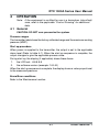
1
DESCRIPTION
1.1 Introduction
The GE Druck RTX 1000A series is a process pressure transmitter that measures
the pressure of liquid, gas or vapor and gives an analog output proportional to
the applied pressure. The transmitter is available in a compact and lightweight
metal housing with facilities for direct mounting to pipeline installations. The type
of housing is specified in the order.
To adjust the transmitter operation, there are push-buttons and switches on the
electronics module
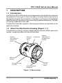
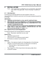
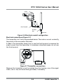
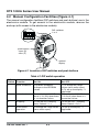
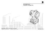
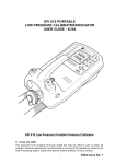
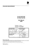
1.2 About the Electronics Housing (Figure 1-1)
The electronics housing contains a digital pressure module (DPM), electronics
module, connecting cables and the terminal block.
end-cap
(with access to
the terminal
block)
electrical
conduit
entry
name plate
end-cap
(with access to
the electronics
module)
electronics
housing
housing
locking
screw
certification label
(If fitted)
process pressure
connection
Figure 1-1 General view
1-1
KA332 Issue No. 1
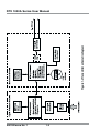
Figure 1-2 Transmitter schematic diagram
RTX 1000A Series User Manual
KA332 Issue No. 1
1-2
RTX 1000A Series User Manual
Digital Pressure Module (DPM) - (Figure 1-2)
The sensing element in the DPM is constructed from a micro-machined silicon
diaphragm assembly bonded to a stainless steel or Hastelloy body. A Hastelloy
isolation diaphragm and silicone fluid isolates the sensing element from the
process media.
The sensor piezo-resistors, diffused into the surface of the silicon diaphragm,
produce a signal in response to applied pressure. The accuracy of the sensor
element is enhanced by measuring the residual errors over its operating
temperature and pressure range and applying digital compensation in the
transmitter electronics.
Electronics Module (Figure 1-2)
The electronics module uses microprocessor technology to give a compact circuit
with the minimum of components. The module produces an extremely stable
signal unaffected by changes in ambient temperature.
An optional LCD shows a value proportional to the measured pressure. Unless
an alternative configuration is specified in the order, the factory configuration
shows the pressure value as a percentage of the calibrated span. To change the
configuration, refer to section 4.
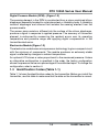
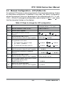
1.3 Identification Codes (Table 1-1)
Table 1-1 shows the identification codes for the transmitter. Before you install the
transmitter, use this table to make sure that the data on the transmitter is correct.
1-3
KA332 Issue No. 1
RTX 1000A Series User Manual
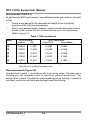
Table 1-1 Identification codes
RTX 10
Base Model Number
Code
Diaphragm
Process Wetted Body
Fill Fluid
00
Hastelloy C *
316 stainless steel *
Silicone oil
10
Hastelloy C
Hastelloy C
Silicone oil
20
Inconel 625*
Inconel 625*
Silicone oil
Code
Output
A
4 - 20 mA
Code
Max Span
Min Span
Notes
04
0 - 10 psi
0 - 1.0 psi
Gauge or absolute
07
0 - 30 psi
0 - 3.0 psi
Gauge or absolute
10
0 - 100 psi
0 - 10 psi
Gauge or absolute
13
0 - 300 psi
0 - 30 psi
Gauge or absolute
16
0 - 1,000 psi
0 - 100 psi
Gauge or absolute
18
0 - 3,000 psi
0 - 300 psi
Sealed gauge or absolute
22
0 - 10,000 psi
0 - 1000 psi
Sealed gauge or absolute
24
0 - 20,000 psi**
0 - 2000 psi
Sealed gauge or absolute
Code
Type
A
Absolute
G
Gauge (sealed gauge for ranges above 1,000 psi)
Code
Process Connection
1
G½ female
2
½-14 NPT female
3
G½ male to BS EN 837-1 (DIN 16288)
4
½ NPT male
5
9/16" tube Autoclave Engineers medium pressure, SF562CX20 female***
Code
N
Electrical Entry
½-14 NPT female (via adaptor)
Code
Electronics Housing
Aluminum alloy
Aluminum alloy
S
Stainless steel
Nickel plated aluminum bronze
Code
Approvals
0
Safe area
F
FM & CSA IS / Explosionproof / Division 2
Code
Example identification code
RTX10
-
00
-
A
-
07
-
G
-
2
-
N
0
-
End-caps
0
0
-
0
-
Options
None
LA
Digital indicator
B
Bracket mounting
T
DIN 3.1B material certificate
0
*
Only available with range code 24, process connection code 5. Not available with CSA or FM
approval.
**
Range code 24 (0-20,000 psi) only applies to RTX 1020 models.
*** Process connection code 5 (autoclave fitting) only applies to range code 24.
KA332 Issue No. 1
1-4
RTX 1000A Series User Manual
2
TECHNICAL DATA
2.1 Pressure Ranges
The transmitter is supplied in one of the standard (zero based) ranges or it can
be calibrated to any acceptable intermediate span. Refer to table 1-1.
The transmitter label shows the factory calibrated range and the maximum working
pressure (MWP). The upper range limit (URL) = MWP.
2.2 Environment Data
Service ........................................................................... Liquid, gas or vapor
Pollution Degree ........................................................................................... 2
Installation (over-voltage) Category ........................................................... II
Temperature
ambient (Not CSA or FM approved) ........ -40°F to +185°F (- 40°C to +85°C)
(LCD Option) .....................................-4°F to +158°F (- 20°C to +70°C )
ambient (CSA or FM approved) .............................. minimum: -40°F (- 40°C)
.............................................. maximum: Refer to the product approval label.
process .................................................. -40°F to +248°F (- 40°C to +120°C)
compensated ............................................ -40°F to +185°F (- 40°C to +85°C)
Humidity limit
................................................................................................... 0 - 100% RH
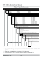
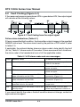
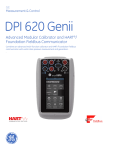
2.3 Performance Data
Range adjustment
0
(psi a)
Minimum span
(URV - LRV): ≥ 10% URL
LRV (or URV)
-15 (psi g)
URL
URV (or LRV)
Lower range value (LRV) = 4 mA pressure value
Upper range value (URV) = 20 mA pressure value
Figure 2-1 Range limits
Figure 2-1 shows the limits for range adjustment. For example:
Span: The minimum span available for a 30 psi device is 3 psi
(10:1 down-ranging).
2-1
KA332 Issue No. 1
RTX 1000A Series User Manual
Zero offset: A 30 psi (MWP) gauge device can give 4 to 20 mA in the range
-15 psi to 30 psi. For example: If the span is 3 psi, 4 to 20 mA is available anywhere
in the range up to a maximum zero offset of 27 psi (calibrated
range = 27 to 30 psi).
Accuracy
0.15% of calibrated span. This includes non-linearity, hysteresis and repeatability.
Long term stability
At standard reference conditions, the maximum change in calibration is not more
than 0.2% URL in a five year period.
Time response
Update rate (Compensated pressure reading) ................................... 100 ms
Damping (DIP switch selection) ............ 0.1 or 1 s to reach 63% of final value
Temperature effects
-40°F to -4°F (-40°C to -20°C): ..................................... 0.5% URL +1% span
-4°F to +122°F (-20°C to +50°C): ........................... 0.25% URL +0.75% span
+122°F to +185°F (+50°C to +85°C): ............................ 0.5% URL +1% span
Mounting position effect
Negligible effect. For ranges below 10 psi, you can adjust the `g' offset effect with
the zero offset control.
Error conditions (NAMUR NE 43 compliant)
Failure mode (< 3.6 or > 21 mA) .......................... DIP Switch selected mode
(This function is always in operation)
•
Under range (DIP switch 2 off) ................................... 3.8 mA minimum
•
Over range (DIP switch 2 on) ................................... 20.5 mA maximum
An optional LCD shows the applicable alarm data. If the pressure is not in the
upper or lower range limits, the pressure value on the display will flash.
Turn-on time
...................................................................................................... 2 seconds
Electronics housing
Material .................................. Aluminum alloy with polyester powder coating
or ................... Stainless steel with nickel plated aluminum bronze end-caps
Environmental protection ............................................................... NEMA 4X
KA332 Issue No. 1
2-2
RTX 1000A Series User Manual
Overpressure
These pressure values will not degrade performance:
................................................................................ 6 x URL for 10 psi range
................................ 4 x URL (2,000 psi max) for ranges: 30 psi to 1,000 psi
....................... 2 x URL (13,000 psi max) for ranges: 3,000 psi to 10,000 psi
..................................................................... 30,000 psi for 20,000 psi range
Pressure containment
These pressures may damage the sensor but there is no leakage of the process
media.
.............................................................................. 10 x URL for 10 psi range
..................... 6 x URL (3,000 psi max) for ranges: 30 psi to 1,000 psi gauge
................................................. 3,000 psi for ranges up to 1,000 psi absolute
... 20,000 psi for ranges: 3,000 psi to 10,000 psi sealed gauge and absolute
..................................................................... 30,500 psi for 20,000 psi range
Process media
A liquid, gas or vapor compatible with a fully welded assembly that includes:
•
A Hastelloy C276 diaphragm, and a body that is made of either
316 stainless steel or Hastelloy C276. Complies with NACE MR-01-75.
•
Inconel 625 (20,000 psi range, range code 24 only).
Sensor fill fluid
...................................................................................................... Silicone oil
Output current
(two wire configuration) .................................................................. 4 - 20 mA
The output is proportional to the calibrated pressure range.
Supply voltage (at the terminals)
Safe area ................................................................................ 12 to 35 V DC
Hazardous area ............................ Refer to the applicable "Control Drawing".
2-3
KA332 Issue No. 1
RTX 1000A Series User Manual
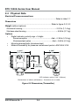
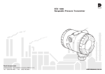
2.4 Physical Data
Electrical/Process connections
............................................................................................ Refer to table 1-1
Dimensions
.................................................................................... Refer to figure 2-2, 2-3
Weight (without options)
Aluminum housing ............................................................. ≈ 2.51 lb (1.14 kg)
Stainless steel housing ........................................................ ≈ 5.95 lb (2.7 kg)
Options
•
Digital indicator: polarity sign + 5 digits
Aluminum option ........................................... Add ≈ 0.35 lb (0.16 kg)
Stainless steel option ...................................... Add ≈ 0.66 lb (0.3 kg)
•
Mounting bracket/bolts (stainless steel)
•
Material traceability for pressure containment parts to EN10204 3.1B
≈ 4.61"
(117* mm)
≈ 3.62"
(92 mm)
3.19"
(81 mm)
≈ 4.21"
(107 mm)
*LCD indicator option: 5.43" (138 mm)
Dimensions in inches (millimeters) - illustration not to scale
Figure 2-2 Dimensions (Transmitter)
KA332 Issue No. 1
2-4
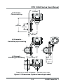
RTX 1000A Series User Manual
(a) Example Panel mounting
6.5"
(165 mm)
4.4"
(113 mm)
2.8"
(70 mm)
3.2"
(82 mm)
(b) Examples Horizontal pipe mounting
(c) Example Vertical pipe mounting
4.4"
(113 mm)
0.8"
(20 mm)
2.8"
(70 mm)
Dimensions in inches (millimeters) - illustration not to scale
Figure 2-3 Dimensions (Optional mounting bracket)
2-5
KA332 Issue No. 1
RTX 1000A Series User Manual
KA332 Issue No. 1
2-6
RTX 1000A Series User Manual
3
INSTALLATION
Note: If the equipment is certified for use in a hazardous (classified)
area, refer to the applicable "Control Drawing" for additional
data.
3.1 Introduction
The following procedures detail the correct installation of the unit.
Use qualified plant installation personnel and follow good engineering practice
at all times.
WARNINGS:
1.
2.
3.
OBSERVE APPROPRIATE LOCAL SAFETY INSTRUCTIONS.
BEFORE INSTALLATION, EXAMINE ALL FITTINGS AND EQUIPMENT
FOR DAMAGE AND MAKE SURE THAT ALL EQUIPMENT IS TO THE
CORRECT PRESSURE RATING.
USE THE IDENTIFICATION CODE ON THE TRANSMITTER TO MAKE
SURE THAT IT HAS THE CORRECT SPECIFICATION FOR THE
INSTALLATION (REFER TO TABLE 1-1).
3.2 Special Tools and Equipment
The following special tools and equipment are required.
Note: Equivalent substitutes can be used.
Special tools
•
•
•
Applicable torque wrench
GE Druck UPS-II [to measure current output]
Multimeter [to measure loop resistance]
Materials
•
•
•
•
Piping - the necessary length and rating depends on the distances.
Fittings to connect the above items including (but not limited to):
- Pipe tee (steam or high temperature liquid)
- Pipe fittings
Pipe compound or Teflon tape (where local piping codes allow)
Loctite PST sealant
3-1
KA332 Issue No. 1
RTX 1000A Series User Manual
3.3 Location and Mounting (Figure 3-3)
Although designed to withstand harsh industrial environments, the transmitter
should be located to minimize the following:
•
Vibration
•
Ambient temperature fluctuations
•
Physical impact or shock
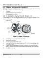
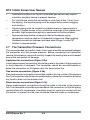
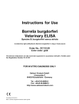
3.4 To Rotate the Display Thru 90° (Figure 3-1)
If applicable, use the following procedure to turn the optional display in the
electronics housing.
spacer (x4)
PCB
power
cables
DPM
cables
display
bezel
screw/washer (x4)
end-cap
Figure 3-1 Display - Turn thru 90°
1.
2.
3.
4.
5.
6.
Isolate the power supply to the transmitter.
Remove the end-cap.
Loosen each screw/washer (x4).
Turn the PCB and the display bezel thru 90° until the screws align with
the spacers again.
Tighten each screw/washer (x4) back in position, but make sure that
there is not too much force on the cables, and that they are not caught.
Attach the end-cap.
KA332 Issue No. 1
3-2
RTX 1000A Series User Manual
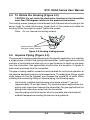
3.5 To Rotate the Housing (Figure 3-2)
CAUTION: Do not rotate the electronics housing on the transmitter
more than 180 degrees relative to the pressure connection.
Two locking screws (hexagon socket screws) lock the electronics housing to the
sensor body. To rotate the housing, loosen both of the screws and rotate the
housing. When the angle is correct, tighten the screws.
Note: Do not remove the locking screws.
locking screws
(hexagon socket screws)
Figure 3-2 Housing locking screws
3.6 Impulse Piping (Figure 3-3)
The purpose of arranging impulse piping for the specific application is to maintain
a single phase of fluid in the piping and transmitter. Liquid applications should
maintain a liquid state and allow any air or gas formation to travel up and away
from the transmitter. Gas applications should allow the formation of liquids to
drain down and away from the transmitter.
The pipe or tubing used for connection must be rated for continuous operation at
the pipeline designed pressure and temperature. Threaded pipe fittings create
voids (where air can be trapped) and increase the possibility of leaks. When
installing the connecting tubing or impulse piping, the following apply:
•
•
Horizontally installed impulse piping must slope at least 1" per foot
(approximately 75 mm per meter). For liquid and steam applications the
piping must slope down towards the transmitter. For gas applications the
piping must slope down away from the transmitter.
Impulse piping should be kept as short as possible and maintained at
ambient temperature avoiding fluctuations and gradients.
3-3
KA332 Issue No. 1
RTX 1000A Series User Manual
•
•
•
•
Installations outdoors for liquid or saturated gas service may require
insulation and heat tracing to prevent freezing.
For installations where the transmitter is more than 6 feet (1.8 m) from
the tapping, the impulse piping must be supported to prevent sagging
and vibration.
Impulse piping must be located in protected areas or against walls or
ceilings. If routed across a floor, protective coverings or kick plates must
be used. High temperature piping or equipment should be avoided.
Appropriate pipe sealing compound rated at the design piping
temperature must be used on all threaded connections. When making
threaded connections between stainless steel fittings, Loctite PST
Sealant is recommended.
3.7 The Transmitter Pressure Connections
The recommended connection uses a two-valve manifold connected between
the transmitter and the process pressure. Before connecting the transmitter
remove the protection caps and carefully inspect the sealing face and threaded
bore of the connection for damage.
Liquid service connections (Figure 3-3a)
Liquid measurement connections should be made to the side of the process line
to avoid deposits of sediment. The transmitter should be mounted beside or
below the connection so that gases vent into the process line.
Gas service connections (Figure 3-3b)
Gas measurement connections should be made to the top or side of the process
line. The transmitter should be mounted beside or above the connection allowing
any liquid to drain into the process line.
Steam service connections (Figure 3-3c)
Steam measurement connections should be made to the side of the process
line. The transmitter should be mounted below the connection so that the piping
remains filled with condensate. Live steam must not come into contact with the
transmitter; to prevent this the lines should be filled with water or condensate.
KA332 Issue No. 1
3-4
RTX 1000A Series User Manual
two-valve
manifold
two-valve
manifold
(a) Liquid service
two-valve
manifold
(b) Gas service
set length
for cooling
plugged tee-piece
for sealing fluid
(water, condensate)
(c) Steam service
Figure 3-3 Piping arrangements
3-5
KA332 Issue No. 1
RTX 1000A Series User Manual
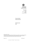
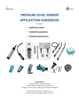
3.8 Liquid Level Measurement (Figure 3-4)
Gauge pressure transmitters can be used to measure liquid level in an open or
vented tank by measuring the hydrostatic pressure head. The head pressure
can be calculated by multiplying the liquid height above the transmitter diaphragm
by the specific gravity of the liquid.
The tank's volume and shape does not affect the head pressure. If the transmitter
is mounted below the zero point (minimum level) of the measured range, zero
suppression will be required.
maximum level
zero
suppression
minimum level
Figure 3-4 Open tank level measurement
Calculations
Min. level
=
=
(40" x 1.1) inH2O
44" inH2O
Max level
=
=
=
([40 + 200] x 1.1) inH2O
(240 x 1.1) inH2O
264 inH2O
Range
=
44 to 264 inH2O
(Span
=
220 inH2O)
KA332 Issue No. 1
3-6
RTX 1000A Series User Manual
3.9 Electrical Data
Note: If the equipment is certified for use in a hazardous (classified)
area, refer to the applicable "Control Drawing" for additional
data.
WARNING: SWITCH OFF AND ISOLATE THE POWER SUPPLY BEFORE
CONNECTING OR DISCONNECTING THE TRANSMITTER.
CAUTIONS:
1.
The transmitter uses DC power in a 2-wire system to control current
through a resistive load.
2.
Do not apply more than 35 Volts to the loop circuit. The transmitter
may be damaged.
General
The electrical installation must comply with local wiring codes and standards. To
get the full performance from the transmitter, carefully choose the wiring scheme
to be used and take care connecting the transmitter.
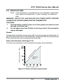
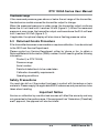
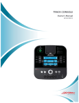
Power and maximum load (Figure 3-5)
e
nc
ta
sis
re
um
im
ax
m
Resistive Loop Load - Ohms
The total loop resistance must include the connection wire resistance.
operating
region
Loop DC Power - Volts
Figure 3-5 Power and load requirements
3-7
KA332 Issue No. 1
RTX 1000A Series User Manual
Wire selection (Table 3-1)
To get the best EMC performance, use shielded twisted pair cable for the field
wiring.
•
Select a wire gauge for the required total length so the transmitter
operates within the load requirements.
•
When using external power supplies, make sure the connection polarity
allows current to flow into the +ve terminal and out of the -ve terminal.
Refer to figure 3-7.
Table 3-1 Wire resistance
AWG
Wire Diameter
Inches
mm
Loop Resistance
Ohms/Foot
Ohms/Meter
16
0.0508
(1.291)
0.0082
0.0264
18
0.0403
(1.024)
0.0128
0.0418
20
0.0320
(0.812)
0.0204
0.0666
22
0.0254
(0.644)
0.0322
0.1060
24
0.0201
(0.511)
0.0514
0.1680
Note: The typical values for resistance per length are doubled as
the circuit is a direct current loop.
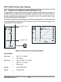
Electrical conduit (Figure 3-6)
Use electrical conduit in accordance with local wiring codes. The electronics
housing has two threaded holes for electrical conduit connections. The
configuration in figure 3-6 prevents moisture getting into the housing. If conduit is
not used, use the correct cable gland/plugs to seal the housing.
KA332 Issue No. 1
3-8
RTX 1000A Series User Manual
plug
min: 2"
(50 mm)
flex Conduit
conduit
tee
to drain
Figure 3-6 Electrical conduit configuration
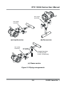
Electrical connections (Figure 3-7)
The transmitter is a 2-wire loop powered device. The marks +ve and -ve identify
the polarity of the connection terminals.
A label in the transmitter shows how to use the third terminal to measure the
output current from the transmitter. In hazardous (classified) areas, do not use
this third terminal.
power
supply
Figure 3-7 Transmitter connections
Because the transmitter circuit is isolated from the housing, one of the signal
wires (+ve or -ve) can be earthed (grounded) if necessary.
3-9
KA332 Issue No. 1
RTX 1000A Series User Manual
3.10 System Checks
Leak test
Before the system is filled and/or commissioned, do a leak test with compressed
air (or other inert compressed gas) or water. The minimum test pressure must be
equal to the normal operating pressure. The maximum pressure is the MWP.
•
Apply pressure at a convenient point on the system.
•
Apply an applicable leak test solution to the impulse piping, valves,
transmitter connections and joints.
•
Look for a continuous stream of bubbles.
•
Bleed the system.
•
Do all the necessary repairs, and test the system again.
•
Return the system to the original configuration.
Transmitter test
Connect the necessary instruments to monitor the pressure signal . If necessary,
connect a milliammeter to measure the output from the transmitter.
•
Apply power to the transmitter.
•
Apply the applicable pressure.
•
Monitor the pressure signal.
Refer to the 'Operation' section for the procedures to set up and operate the
transmitter.
KA332 Issue No. 1
3-10
RTX 1000A Series User Manual
4
OPERATION
Note: If the equipment is certified for use in a hazardous (classified)
area, refer to the applicable "Control Drawing" for additional
data.
4.1 General
CAUTION: DO NOT over-pressurize the system.
Pressure ranges
The transmitter label shows the factory calibrated range and the maximum working
pressure (MWP).
Start up procedure
When power is supplied to the transmitter, the output is set to the applicable
alarm level (Refer to table 4-1). When the start up sequence is complete, the
output changes to give the applicable process value.
During start up, the display (if applicable) shows these items:
1.
the LCD test: -8.8.8.8.8
2.
the software version (example: 1.00.00)
When the start up sequence is complete, the display shows a value proportional
to the measured pressure.
Alarm/Error conditions
Refer to the 'Maintenance' section.
4-1
KA332 Issue No. 1
RTX 1000A Series User Manual
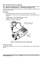
4.2 Manual Configuration Facilities (Figure 4-1)
The manual configuration facilities (DIP switches and push buttons) are in the
electronics module. To get access to the electronics module, remove the
end-cap (with access to the electronics module).
DIP switches
1 to 4
push buttons:
- span (S)
- zero (Z)
optional
display
Figure 4-1 Location of DIP switches and push buttons
Table 4-1 DIP switch operation
DIP
Switch
Function
Set ON
Set OFF
1
Write Protection
To prevent accidental
changes to the EEPROM
values.
2
Alarm level
To use the high NAMUR
alarm (> 21 mA) when there
is a transmitter failure.
1) To change the range
values (zero and/or span).
2) To set up the display - if
applicable.
To use the low NAMUR alarm
(< 3.6 mA) when there is a
transmitter failure.
3
Damping
To use the ON_Damping
factor. Default = 1 s
To use the OFF_Damping
factor. Default = 0.1 s
4
Push button
operation
To change the range values
(zero and/or span).
To set up the display - if
applicable.
KA332 Issue No. 1
4-2
RTX 1000A Series User Manual
4.3 Manual Configuration - LCD (Table 4-2)
An optional LCD shows a value proportional to the measured pressure. Unless
an alternative configuration is specified in the order, the factory configuration
shows the pressure value as a percentage of the calibrated span (0% = 4 mA,
100% = 20 mA). To change the configuration, refer to table 4-2 ( 0 , 1 , and . show
that the character flashes on the display).
Table 4-2 Steps to change the LCD configuration
Step
Operation
Result and/or example
(Example device: - 1 to 1 psi)
Refer to table 4-1
1.
Set DIP switches 1 and 4 to OFF.
2.
Press S and Z together.
3.
Set the decimal point position:
Press Z
___
4.
5.
__
.
__
___
_
.
Go to the next step (ZERO):
Wait 5 seconds or press S and Z together.
Set the lower display value (LDV) to show
an applicable 4 mA value:
____
.
2ErO, then 0 . 0 0 0 0
a. To increase the value of a digit
(0 ... 9, 0 ... ), press Z.
0.0000
1.0000
b. To select the next digit, press S
1.0000
1.0000
6.
Go to the next step:
Wait 5 seconds or press S and Z together.
1.0000
7.
Set the value to positive or negative:
Press Z.
1.0000
8.
Go to the next step (SPAN):
Wait 5 seconds or press S and Z together.
SPAn, then 0 . 0 0 0 0
9.
Set the upper display value (UDV) to show
an applicable 20 mA value:
Repeat steps 5 to 7.
1.0000
10.
Return to normal operation:
Wait 5 seconds or press S and Z together.
0.0000
11.
Set DIP switch 1 to ON.
Refer to table 4-1
4-3
-1.0000
KA332 Issue No. 1
RTX 1000A Series User Manual
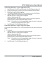
4.4 Manual Configuration - Calibration (Figure 4-2)
To get accurate results, do the calibration in conditions where the pressure and
temperature are stable.
Equipment
•
•
•
A precision pressure calibrator such as the GE Druck DPI 605 or
DPI 610/615. The accuracy of the supplied pressure must be better than
±0.075%.
In safe areas, a 12 to 35 Volt DC power supply
(separate or part of another system)
Fittings and tubing as required
excitation voltage and
4 mA to 20 mA signal
transmitter
precision
pressure
calibrator
Figure 4-2 Calibration set-up for safe areas
Calibration ranges
Set any span value from 10 to 100% of the URL. Refer to the 'Technical Data'
section.
KA332 Issue No. 1
4-4
RTX 1000A Series User Manual
Calibration adjustment - Lower range value (LRV)
1.
2.
3.
4.
5.
Set DIP switch 1 to OFF and DIP switch 4 to ON (Refer to table 4-1).
Supply the necessary pressure and let the pressure become stable.
Press the S and Z buttons together.
The optional display shows CAL, then a pressure value that flashes.
Option - Return to normal operation without change:
Wait 25 seconds or press S and Z together.
Option - Save the new LRV:
Press the Z button. The signal output is set to 4 mA and the optional
display shows a pressure value that does not flash.
Note: If the value is not in the applicable range, the value is ignored
and the optional display shows 'Error'.
Set DIP switch 1 to ON (Refer to table 4-1).
Calibration adjustment - Upper range value (URV)
To minimize measurement errors, do the LRV before the URV, then follow these
steps:
1 - 3 As above.
4.
Option - Return to normal operation without change:
Wait 25 seconds or press S and Z together.
Option - Save the new URV:
Press the S button. The signal output is set to 20 mA and the optional
display shows a pressure value that does not flash.
Note: If the value is not in the applicable range, the value is ignored
and the optional display shows 'Error'.
5.
Set DIP switch 1 to ON (Refer to table 4-1).
4-5
KA332 Issue No. 1
RTX 1000A Series User Manual
KA332 Issue No. 1
4-6
RTX 1000A Series User Manual
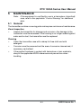
5
MAINTENANCE
Note: If the equipment is certified for use in a hazardous (classified)
area, refer to the applicable "Control Drawing" for additional
data.
5.1 General
The transmitter contains no moving parts and requires a minimum of maintenance.
Visual inspection
•
Inspect the transmitter for damage and corrosion. Any damage to the
transmitter must be assessed. If the housing is no longer sealed against
water and/or dust, the transmitter must be replaced.
Cleaning
•
Clean the transmitter case with a damp lint-free cloth and mild
detergent.
•
Corrosion must be removed and the area of corrosion cleaned and, if
necessary, neutralized.
•
If the product has been in contact with hazardous or toxic materials,
obey all the applicable MSDS references and precautions when
handling.
5-1
KA332 Issue No. 1
RTX 1000A Series User Manual
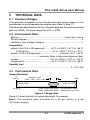
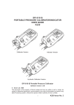
5.2 Fault Finding (Figure 5-1)
If the measured pressure goes above URV or goes below LRV, the output signal
will saturate at the following values:
Figure 5-1 Fault finding from the output signal
Failure alarm indications (Table 5-1)
If there is a specified fault condition, the transmitter output changes to the specified
NAMUR alarm level. The alarm level is set by the position of DIP switch 2 (refer
to table 4-1).
If applicable, the optional display shows an alarm code to help identify the fault
(AL xx). Table 5-1 shows some of the codes. If there are several fault conditions,
the alarm code is the hexadecimal sum of all the applicable codes.
Table 5-1 LCD alarm codes and error messages
Code
Possible cause
To correct the error
Too much positive or negative pressure.
Supply pressure in the specified
limits for the device.
DPM error
Power off, wait 25 seconds, then
power on again.
DPM data not received
Power off, wait 25 seconds, then
power on again.
LCD adjustment has loosened the DPM
cable connection on the PCB.
Examine the DPM cable
connection (Figure 3-1).
AL 08
LCD adjustment has loosened the DPM
cable connection on the PCB.
Examine the DPM cable
connection (Figure 3-1).
Error
Configuration error. The range is not in the
specified limits for the device.
Refer to section 2 for the specified
range limits.
Prot
Configuration error. DIP switch 1 set to ON
(Write protect).
Set DIP switch 1 to OFF, then
follow the procedures in Section 4.
AL 02
AL 04
If you cannot identify the code or the fault condition does not change, contact an
approved service agent.
KA332 Issue No. 1
5-2
RTX 1000A Series User Manual
Over/under range
If the measured pressure goes above or below the set range of the transmitter,
the electronics module causes the transmitter output to change.
When the measured pressure is under range, the transmitter output continues
below the 4.0 mA level until it reaches 3.8 mA (figure 5-1). When the measured
pressure is over range, the transmitter output continues above the 20.0 mA level
until it reaches 20.5 mA (figure 5-1).
If applicable, the optional display will also show a flashing pressure value.
5.3 Returned Goods Procedure
If the transmitter becomes unserviceable or requires calibration, it can be returned
to the GE Druck Service Department.
Please contact our Service Department, either by 'phone or fax, to obtain a
Returned Material Authorization (RMA) number. You will need to give the following
information:
Product (i.e. RTX 1000A)
Pressure range
Serial number
Details of defect/work to be undertaken
Calibration traceability requirements
Operating conditions
Safety Precautions
You must also tell us if the product has been in contact with hazardous or toxic
materials. Please supply the applicable MSDS references and precautions to be
taken when handling.
Important Notice
Service or calibration by unauthorized sources will affect the warranty and may
not guarantee further performance. If the equipment has "Hazardous (Classified)
area" approval, the approval will also be invalid.
5-3
KA332 Issue No. 1
RTX 1000A Series User Manual
KA332 Issue No. 1
5-4