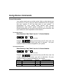
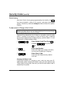
1
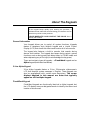
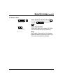
9,67$%$<
6HFXULW\6\VWHP
8VHU*XLGH
ARMED
1
2
OFF
AWAY
4
MAX
SINCE 1946
Liberty System
3
STAY
5
6
TEST
BYPASS
7
8
9
INSTANT
CODE
CHIME
*
0
#
READY
IIIIII
PANIC
HEAT
COOL
BYPASS
ACTIVE
SINCE 1946
N7527-4V1 5/00
File No: S1632
-2-
TABLE OF CONTENTS
System Overview........................................... 4
Panic Keys ..................................................... 25
General Information........................................ 4
Zones.............................................................. 4
Burglary Protection ......................................... 4
Security Codes ............................................... 5
Fire Protection ................................................ 5
Alarms ............................................................ 5
Memory of Alarm ............................................ 6
Phone Access & Voice Response Capability . 6
Paging Feature ............................................... 6
Using Panic Keys ........................................... 25
Types of Panic Alarms.................................... 25
Entry/Exit Delays ........................................... 7
General Information........................................ 7
Exit Alarms ..................................................... 8
About The Keypads....................................... 9
General Information........................................ 9
2-Line Alpha Keypad ...................................... 9
Fixed-Word Keypad........................................ 9
Fixed-Word Keypad Displays ......................... 10
Functions Of The Keypads ........................... 12
Checking For Open Zones............................ 15
Using the
✱
Key ..................................... 15
Arming Perimeter Only (Entry Delay ON).... 16
Using the
3
Key ...................................... 16
Arming Perimeter Only (Entry Delay OFF) .. 17
Using the
7
Key ...................................... 17
Arming All Protection (Entry Delay ON) ...... 18
Using the
2
Key ...................................... 18
Arming All Protection (Entry Delay OFF) .... 19
Using the
4
Key ...................................... 19
Disarming and Silencing Alarms ................. 20
Using the
1
Key ...................................... 20
Memory of Alarm ............................................ 20
Bypassing Protection Zones ........................ 22
Using Device Commands ............................. 26
General Information........................................ 26
Paging Feature............................................... 27
General Information........................................ 27
Code Format................................................... 27
Examples........................................................ 27
Using the Keyswitch ..................................... 28
General Information........................................ 28
Arming/ Disarming .......................................... 28
Security Codes .............................................. 29
General Information........................................ 29
Babysitter Code .............................................. 29
Duress Code................................................... 29
Quick Arming .................................................. 30
To Add a User or Change a User's Code ....... 30
To Delete a User ............................................ 31
Testing the System........................................ 32
Using the
5
Key ....................................... 32
Trouble Conditions........................................ 34
Typical “Check” Displays ................................ 34
Fire Alarm System......................................... 37
General Information........................................ 37
In Case Of Fire ............................................... 37
Recommendations for Proper Protection ... 39
Recommendations for Smoke and Heat
Detectors ........................................................ 39
Recommendations for Proper Intrusion
Protection ....................................................... 41
Emergency Evacuation ................................. 42
Maintaining Your System.............................. 43
Taking Care of Your System .......................... 43
Replacing Batteries in Wireless Sensors........ 43
Routine Care .................................................. 44
Key ....................................... 22
Quick Guide to System Functions ............... 45
Summary of Audible Notification................. 46
Quick Bypass.................................................. 23
Displaying Bypassed Zones ........................... 23
Glossary ......................................................... 47
Using the
6
Chime Mode ................................................... 24
Using the
9
Key ...................................... 24
Index ............................................................... 54
-3-
System Overview
General Information
Congratulations on your ownership of a Bay Alarm Security System.
You've made a wise decision in choosing it, for it represents the latest
in security protection technology today.
This system offers you three forms of protection: burglary, fire and
emergency. Your system consists of at least one keypad that provides
control of system operation, and includes various sensors that provide
perimeter and interior burglary protection, plus smoke or combustion
detectors designed to provide early warning in case of fire.
The system uses microcomputer technology to monitor all protection
zones and system status, display appropriate information on the
keypad(s) used with the system, and initiate appropriate alarms.
Your system may also have been programmed to automatically send
alarm or status messages over the phone lines to a central alarm
monitoring station.
Zones
Your system's sensing devices have been assigned to various "zones."
For example, the sensing device on your Entry/Exit door may have
been assigned to zone 01, sensing devices on windows in the master
bedroom to zone 02, and so on. These numbers appear on the display,
along with a description for that zone (if programmed), when an
alarm or trouble condition occurs.
Burglary Protection
Your system provides four modes of burglary protection: STAY,
AWAY, INSTANT, and MAXIMUM, and allows you to BYPASS
selected zones while leaving the rest of the system armed. You must
turn on or "arm" the burglary protection portion of your system before
it senses burglary alarms. The system also provides a CHIME mode,
for alerting users to the opening of protected doors and windows while
-4-
System Overview (cont’d)
the system is disarmed. Refer to the other sections of this manual for
procedures for using these features.
The following table lists the four different arming modes and the
features of each.
ARMING
MODE
AWAY
STAY
INSTANT
MAXIMUM
Exit
Delay
Yes
Yes
Yes
Yes
FEATURES FOR EACH ARMING MODE
Entry
Perimeter
Interior
Delay
Armed
Armed
Yes
Yes
Yes
Yes
Yes
No
No
Yes
No
No
Yes
Yes
Security Codes
At the time of installation, you were assigned a personal four-digit
security code, known only to you. You must enter that 4-digit security
code when arming and disarming the system, and when performing
other system functions. As an additional safety feature, other users
who do not have a need to know your code can be assigned different
security codes. Refer to section titled, “Security Codes” for procedures
for adding security codes to the system.
Fire Protection
The fire protection portion of your security system (if used) is always
active and sounds an alarm if a fire condition is detected. Refer to
section titled, “Fire Alarm System” for important information
concerning fire protection, smoke detectors and planning emergency
exit routes from the premises.
Alarms
When an alarm occurs, both the keypad and external sounders sound,
with the keypad displaying the zone(s) causing the alarm. If your
system is connected to a central monitoring station, an alarm message
is also sent. To stop the alarm sounding, simply disarm the system.
Refer to section titled, “Disarming and Silencing Alarms.”
-5-
System Overview (cont’d)
Memory of Alarm
When an alarm condition occurs, the keypad displays the number of
the zone that caused the problem, and the type of alarm (e.g. “FIRE,”
“ALARM”). It remains displayed until it is cleared by disarming the
system (see “Disarming and Silencing Alarms”).
Phone Access & Voice Response Capability
Your system may include a phone module that permits you to access
the system via a TouchTone telephone, either on-premises or by callin when away. The phone access feature enables you to do the
following:
• Receive synthesized voice messages over the telephone regarding
the status of the security system.
• Arm and disarm the system and perform most function commands
via the telephone, with voice confirmation provided after each
command entry.
Paging Feature
With the paging feature programmed for your system, your pager
responds to certain conditions as they occur in your system. Your
pager displays code numbers indicating the type of condition that has
occurred. Refer to section titled, “Paging Feature” for detailed
information.
-6-
Entry/Exit Delays
General Information
Your system has preset time delays, known as Exit Delay and Entry
Delay. Whenever you arm your system, Exit Delay gives you time to
leave through the designated exit door without setting off an alarm.
Exit Delay begins immediately after entering any arming command,
and applies to all modes of arming protection. If programmed, a slow
beeping will sound throughout the exit delay period.
Entry Delay gives you time to disarm the system when you re-enter
the premises through the designated entrance door. But you must
disarm the system before the entry delay period ends, or an alarm
occurs. The keypad beeps during the entry delay period, reminding
you to disarm the system. There are two entry delays (if
programmed). The first is for your primary entrance and the second
can be used for a secondary entrance, where a longer delay is required
to walk to the keypad to disarm the system.
You can also arm the system with no entry delay at all by using either
the INSTANT or MAXIMUM arming modes. This mode provides
greater security while on the premises.
See your installer for your delay times (you may want to record them
below).
Exit Delay:
seconds
Entry Delay 1:
seconds
Entry Delay 2:
seconds
-7-
Entry/Exit Delays (cont'd)
Exit Alarms
To minimize false alarms sent to the alarm monitoring company,
your system may have been programmed for this feature. Ask
your installer if Exit Alarm is active for your system.
Exit Alarm Active
Whenever you arm the system, the Exit Delay begins. If an entry/exit
door or interior zone is faulted when the Exit Delay ends (e.g., exit
door left open), the system sounds an alarm and starts the entry delay
timer. If you disarm the system before the entry delay ends, the alarm
sound stops and the message "CANCELED ALARM" or "CA" is
displayed on the keypad, along with a zone number indicating the
faulted zone. No message is sent to the alarm monitoring company.
To clear the exit alarm condition (the open zone must be closed before
the display can be cleared), enter your 4-digit security code plus OFF.
If you do not disarm the system before the entry delay ends, and an
entry/exit door or interior zone is still open, the alarm sound
continues and an "exit alarm" message is sent to the alarm
monitoring company. The message “EXIT ALARM” or “EA” is
displayed on the keypad, along with a zone number indicating the
faulted zone. To stop the alarm, the system must be disarmed using
your security code plus OFF key. To clear the display, enter your code
plus OFF a second time.
An exit alarm also results if an entry/exit door or interior zone is
faulted within 2 minutes after the end of the Exit Delay.
-8-
About The Keypads
IMPORTANT
If the keypad beeps rapidly upon entering the premises, it
indicates that an alarm has occurred during your absence and an
intruder may still be on the premises.
LEAVE IMMEDIATELY AND CONTACT THE POLICE from a
nearby safe location.
General Information
Your keypad allows you to control all system functions. Keypads
feature a telephone style (digital) keypad and a Liquid Crystal
Display (LCD) that shows the nature and location of all occurrences.
The keypad also features a built-in sounder that sounds during
alarms and troubles. The keypad also beeps during certain system
functions, such as during entry/exit delay times, in CHIME mode, and
when depressing any of the keys (to acknowledge the key press).
There are two basic types of keypads – a Fixed-Word keypad and an
Alpha keypad (both described below).
2-Line Alpha Keypad
2-line Alpha keypads feature a 2-line, 32-character alphanumeric
LCD that displays system messages in English. These keypads can
also be programmed with custom zone descriptors. The screen
displays depicted in this manual are those that typically
appear on a 2-line Alpha keypad.
Fixed-Word Keypad
Fixed-Word keypads are functionally identical to Alpha keypads, but
the LCD display uses pre-designated words to identify the nature and
location of occurrences.
-9-
About The Keypads (cont'd)
ALARM
CHECK
FIRE
AWAY
STAY
INSTANT
BYPASS
NO AC
CHIME
BAT
ARMED
ARMED
READY
NOT READY
OFF
AWAY
STAY
1
2
3
MAX
TEST
BYPASS
4
5
6
INSTANT
CODE
CHIME
7
8
9
0
#
OFF
AWAY
STAY
MAX
TEST
BYPASS
INSTANT
CODE
CHIME
READY
*
PANIC
SINCE 1946
READY
Liberty System
6128
FIXED-WORD KEYPAD
PANIC
SK6139A-BAY
2-LINE ALPHA KEYPAD
Fixed-Word Keypad Displays
AWAY: All burglary zones, interior
and perimeter, are armed.
STAY: Perimeter burglary zones,
such as protected windows &
doors, are armed.
INSTANT: Perimeter burglary zones are
armed and entry delay is
turned off.
00
ALARM
CHECK
FIRE
AWAY
STAY
INSTANT
BYPASS
NO AC
CHIME
BAT
NOT READY
FIXED-WORD
KEYPAD DISPLAY
BYPASS: One or more burglary
protection zones have been
bypassed.
NOT READY: Appears when burglary portion of the system is not ready for
arming (due to open protection zones).
READY: The burglary system is ready to be armed.
NO AC: Appears when AC power has been cut off. System is operating
on backup battery power.
AC: Appears when AC power is present.
- 10 -
About The Keypads (cont'd)
CHIME: Appears when the Chime feature is activated.
BAT: Low battery condition in a wireless sensor (if zone number
displayed) or low system battery (if no zone number
displayed).
ALARM: Appears when an intrusion has been detected and the system
is armed (also appears during a fire alarm or audible
emergency alarm). Accompanied by the protection zone in
alarm.
CHECK: Appears when a malfunction is detected in the system at any
time; or if an open is detected in a FIRE zone at any time; or a
fault in a DAY/NIGHT burglary zone during a disarmed
period. Accompanied by a display of zone number in trouble.
FIRE: Appears when a fire alarm is present. Accompanied by a
display of the zone in alarm.
- 11 -
Functions Of The Keypads
1
2
5
3
14
4
15
ARMED
6
A
OFF
AWAY
STAY
MAX
TEST
BYPASS
INSTANT
CODE
CHIME
7
B
C
9
10
SINCE 1946
READY
Liberty System
PANIC
8
11
13
12
16
TYPICAL ALPHA KEYPAD
Fixed-Word keypads are functionally similar, except for screen displays.
1. ALPHA DISPLAY WINDOW: A 2line Liquid Crystal Display (LCD).
Displays protection point identification, system status, messages, and
user instructions.
2.
OFF KEY: Disarms the burglary
portion of the system, silences
alarms and audible trouble
indicators, and clears displayed
alarm trouble after the problem has
been corrected.
- 12 -
3.
AWAY KEY: Completely arms
both perimeter and interior
burglary zones for backup
protection by sensing an intruder's
movements through protected
interior areas as well as guarding
protected doors, windows, etc.
Entrance can be made through an
entry delay zone without causing an
alarm if the system is disarmed
before the entry delay time expires.
Functions Of The Keypads (cont'd)
4.
burglary sensors, guarding
protected doors, windows and other
perimeter protection points, and
sounds an alarm if one is opened.
Interior protection is not armed,
which allows movement within your
house without causing an alarm.
Entrance can be made through an
entry delay zone without causing an
alarm if the system is disarmed
before the entry delay time expires.
5.
BYPASS KEY: Removes
individual protection zones from
being monitored by the system.
Displays currently bypassed
protection zones.
8.
CODE KEY: Allows the entry of
additional user codes that can be
given to other users of the system.
10. CHIME KEY: Turns the CHIME
mode on and off. When on, any
entry through a protected delay or
perimeter zone while the system is
disarmed causes a tone to sound at
the keypad(s).
11. READY KEY: When depressed
prior to arming the system, the
keypad displays any open protection
zones monitored by the system.
TEST KEY: Tests the system and
alarm sounder.
7.
9.
MAX KEY: Arms in manner
similar to AWAY mode, but
eliminates the entry delay period,
thus providing maximum
protection. An alarm occurs
immediately upon opening any
protection point, including entry
delay zones.
6.
the entry delay period, offering
greater security while inside and
not expecting any late arrivals. An
alarm occurs immediately upon
opening any perimeter protection
point, including entry delay zones.
STAY KEY: Arms the perimeter
INSTANT KEY: Arms in manner
similar to STAY mode, but turns off
12.
#
KEY: Permits arming of the
system without use of a security
code (“Quick Arm,” if programmed).
13. KEYS 0-9: Used to enter your
individual security access code(s).
14. ARMED INDICATOR: (RED) Lit
when the system has been armed in
the STAY, AWAY, INSTANT, or
MAXIMUM mode.
- 13 -
Functions Of The Keypads (cont'd)
15. INTERNAL SOUNDER: Source of
audible internal warning and
confirmation sounds, as well as
alarms (see "Summary of Audible
Notifications").
16. PANIC KEYS: Some keypads use
key pairs to activate panic alarms,
rather than individual keys. Refer
- 14 -
To Panic Keys for descriptions of
these keys.
IMPORTANT!
When you use the keypad to enter codes and
commands, press the keys within 2 seconds of
one another. If 2 seconds elapse without a key
depression, the entry is aborted and must be
repeated from its beginning.
Checking For Open Zones
Using the
✱
Key
Before arming your system, all protected doors, windows and other
protection zones must be closed or bypassed (see “Bypassing
Protection Zones”). Otherwise the keypad displays a “NOT READY”
message. Using the [✱] key displays all zones that are faulted,
making it easier for you to secure any open zones.
NOTE: A green READY indicator (if present) on the keypad is lit if
the system is ready to be armed. If not lit, the system is not
ready.
NOT READY - PRESS ✱
TO SHOW FAULTS
To show faulted zones:
1.
✱
Press The [✱] Key
Do not enter security code, but simply
press the [✱] key.
2.
FAULT 05 FRONT
UPSTAIRS BEDROOM
Secure Faulted Zones
Typical fault display shows open zones.
Secure or bypass the zones displayed
before arming the system.
3.
✱✱✱✱D I S A R M E D ✱✱✱✱
READY TO ARM
System Can Be Armed
The “READY” message is displayed when
all protection zones have been either
closed or bypassed.
You may now arm the system as usual.
- 15 -
Arming Perimeter Only (Entry Delay ON)
Using the
3
Key
STAY
Use this key when you are staying home, but might expect someone to
use the entrance door later.
When armed in STAY mode, the system sounds an alarm if a
protected door or window is opened, but you may otherwise move
freely throughout the premises. Late arrivals can enter through the
entrance door without causing an alarm, but they must disarm the
system within the entry delay period or an alarm occurs.
Close all protected perimeter windows and doors before
arming (see “Checking for Open Zones”).
The green READY
indicator (if present) on the keypad should be lit if the system is ready
to be armed.
1.
+
(Security Code)
Enter Security Code, Then Press
STAY
3
STAY
Example: 7
2
9
6 then press the
STAY key
or for quick arming
( i f e n a bl e d )
Press the “#” key followed by the
“STAY” Key
Listen For 3 Beeps
The keypad beeps three times and
displays the “ARMED STAY” message.
The “You may exit now” message
disappears at the end of the exit delay
time. The red ARMED indicator also
lights.
You can restart the exit delay at any time after arming in STAY mode
2.
A R M E D ✱✱✱S T A Y ✱✱✱
You may exit now
by pressing the
✴
key. This is useful if you wish to open the
entry/exit door to let someone in after arming the system and avoids
having to disarm the system and then re-arm it again.
- 16 -
Arming Perimeter Only
(Entry Delay OFF)
Using the
7
Key
INSTANT
Use this key when you are staying home and do not expect anyone to
use the entrance door.
When armed in INSTANT mode, the system sounds an alarm if a
protected door or window is opened, but you may otherwise move
freely throughout the premises. The alarm also sounds immediately if
anyone opens the entrance door. Close all protected perimeter
windows and doors before arming (See “Checking for Open
Zones”). The green READY indicator (if present) on the keypad
should be lit if the system is ready to be armed.
1.
+
(Security Code)
7
INSTANT
Enter Security Code, Then Press
INSTANT
Example: 7
or for quick arming
( i f e n a bl e d )
2. A R M E D ✱I N S T A N T ✱
You may exit now
2
9
6 then press the
INSTANT
Press the “#” key followed by the
“INSTANT” Key
Listen For 3 Beeps
The keypad beeps three times and
displays the “ARMED INSTANT”
message. The “You may exit now”
message disappears at the end of the exit
delay time. The red ARMED indicator
also lights.
You can restart the exit delay at any time after arming in INSTANT
mode by pressing the ✴ key. This is useful if you wish to open the
entry/exit door to let someone in after arming the system and avoids
having to disarm the system and then re-arm it again.
- 17 -
Arming All Protection
(Entry Delay ON)
Using the
2
Key
AWAY
Use this key when no one is staying in the premises.
When armed in AWAY mode, the system sounds an alarm if a
protected door or window is opened, or if any movement is detected
inside the premises. You may leave through the entrance door during
the exit delay period without causing an alarm. You may also re-enter
through the entrance door, but must disarm the system within the
entry delay period or an alarm occurs.
Close all protected perimeter windows and doors before
arming (see “Checking for Open Zones”).
The green READY
indicator (if present) on the keypad should be lit if the system is ready
to be armed.
1.
+ 2
(Security Code)
AWAY
or for quick arming
( i f e n a bl e d )
2.
A R M E D ✱✱✱A W A Y ✱✱✱
You may exit now
Enter security code, then press AWAY
Example: 7
2
9
6 then press the
AWAY key
Press the “#” key followed by the
“AWAY” Key
Listen
The keypad beeps twice, or beeps
continuously if exit warning has been
programmed for your system, and
displays the “ARMED AWAY” message.
The red ARMED indicator also lights.
The “YOU MAY EXIT NOW” portion of
the message disappears when the exit
delay expires.
- 18 -
Arming All Protection
(Entry Delay OFF)
Using the
4
Key
MAXIMUM
Use this key when the premises is vacant for extended periods of time
such as during vacation periods, long weekends, etc., or when no one
is expected to be moving through protected interior areas.
When armed in MAXIMUM mode, the system sounds an alarm if a
protected door or window is opened, or if any movement is detected
inside the premises. You may leave through the entrance door during
the exit delay period without causing an alarm, but an alarm is
sounded as soon as someone re-enters.
Close all protected perimeter windows and doors before
arming (see “Checking for Open Zones”). The green READY indicator
(if present) on the keypad is lit if the system is ready to be armed.
Enter Security Code, Then Press
1.
+ 4
MAXIMUM
(Security Code) MAXIMUM
Example: 7
2
9
6 then press the
MAXIMUM key
or for quick arming
( i f e n a bl e d )
2. A R M E D ✱M A X I M U M ✱
You may exit now
Press the “#” key followed by the
“MAXIMUM” Key
Listen
The keypad beeps twice, or beeps
continuously if exit warning has been
programmed for your system, and
displays the “ARMED MAXIMUM”
message (“AWAY/INSTANT” on fixedword keypads). The red ARMED indicator
also lights.
The “YOU MAY EXIT NOW” portion of
the message disappears when the exit
delay expires.
- 19 -
Disarming and Silencing Alarms
Using the
1
Key
OFF
Use the OFF key to disarm the system and to silence alarm and
trouble sounds. See “Summary of Audible Notification” for
information that helps you to distinguish between fire and burglary
alarm sounds.
IMPORTANT: If you return and the main burglary
sounder is on, DO NOT enter the premises, but call the
police from a nearby safe location. If you return after an
alarm has occurred and the main sounder has shut
itself off, the keypad beeps rapidly upon entering,
indicating that an alarm has occurred during your
absence and an intruder may still be on the premises.
LEAVE IMMEDIATELY and CONTACT THE
POLICE from a nearby safe location.
To disarm the system and silence burglary alarms:
1.
+ 1
(Security Code)
OFF
Enter Security Code, Then Press OFF
Example: 7
2
9
6 then press the
OFF key
2.
✱✱✱✱D I S A R M E D ✱✱✱✱
READY TO ARM
Listen For 1 Beep
The “READY” message is displayed (if no
alarms have occurred while armed) and
the keypad beeps once to confirm that the
system is disarmed.
Memory of Alarm
If an alarm occurs, the keypad displays the zone number(s) that
caused the alarm and the type of alarm. These messages remain
displayed until cleared by a user.
- 20 -
Disarming and Silencing Alarms (cont'd)
To clear the display:
Note the zone number displayed and enter an OFF sequence.
Enter Security Code, Then Press OFF
+ 1
(Security Code)
OFF
Example: 7
2
9
6 then press the
OFF key
If the “READY” message does not display, go to the displayed zone
and correct the fault (close windows, etc.). If the fault cannot be
corrected, notify your alarm company.
- 21 -
Bypassing Protection Zones
Using the
6
Key
BYPASS
This key is used when you want to arm your system with one or more
zones intentionally unprotected. Bypassed zones are unprotected and
do not cause an alarm when violated while your system is armed. All
bypasses are removed when an OFF sequence (security code
plus OFF) is performed. Bypasses are also removed if the arming
procedure that follows the bypass command is not successful.
The system does not allow fire zones to be bypassed.
To bypass zones, the system must be disarmed first.
1.
+ 6
(Security Code)
BYPASS
Enter Security Code, Then Press
BYPASS
Example: 7
2
9
6 then press the
BYPASS key
2.
(Zone Numbers)
Enter Zone Numbers
Enter the zone number(s) for the zones to
be bypassed (e.g., 01, 02, 03, etc.).
Important! All single-digit numbers
must be preceded by a zero (for example,
enter 01 for zone 1).
3. B Y P A S S 0 7 F R O N T
UPSTAIRS BEDROOM
Typical bypass message
4.
- 22 -
DISARMED BYPASS
READY TO ARM
Wait
The keypad displays the word “BYPASS”
along with each bypassed zone number.
Wait for these zones to be displayed, to be
sure that intended zones are bypassed.
Arm As Usual
Arm the system as usual when the
keypad displays the "READY ” message.
Bypassing Protection Zones (cont'd)
Quick Bypass
Your system (if programmed to do so) would allow you to easily
bypass all open (faulted) zones without having to enter zone numbers
individually. Ask your installer if this feature is active.
1.
+ 6
(Security Code) BYPASS
Enter Security Code, Then Press
BYPASS
Example: 7
2. B Y P A S S 0 7 F R O N T
UPSTAIRS BEDROOM
Typical bypass message
3.
DISARMED BYPASS
Ready to Arm
2
9
6 then press the
BYPASS key
Wait
In a few moments, all open zones are
displayed along with the word “BYPASS.”
Wait for these zones to be displayed
before arming. Arming the system
before zones are displayed eliminates
all bypasses.
Arm As Usual
Arm the system as usual when the
keypad displays the "READY ” message.
Displaying Bypassed Zones
For determining what zones have been previously bypassed. Bypassed
zones can be displayed only when the system is disarmed, and when
the “BYPASS” message shown in step 3 above is displayed.
1.
+ 6
(Security Code) BYPASS
Enter Security Code, Then Press
BYPASS
Example: 7
2
9
6 then press the
BYPASS key
2. B Y P A S S 0 7 F R O N T
UPSTAIRS BEDROOM
Typical bypass message
Wait
In a few moments, all open zones are
sequentially displayed along with the
word “BYPASS.”
- 23 -
Chime Mode
Using the
9
Key
CHIME
Your system can be set to alert you to the opening of a door or
window† while it is disarmed by using CHIME mode. When activated,
three beeps sound at the keypad whenever a protected perimeter door
or window is opened.
† Or selected doors or windows if chime-by-zone feature is
active. Ask installer if this feature applies to your system.
Pressing the ✱
key displays the open protection points.
Note that the CHIME mode can be activated only when the system is
disarmed.
To turn CHIME mode on:
1.
+
(Security Code)
9
CHIME
Enter Security Code, Then Press
CHIME
Example: 7
2
9
6 then press the
CHIME key
2.
DISARMED CHIME
Ready to Arm
View
The “CHIME” message displays while
CHIME mode is on.
To turn CHIME mode off:
1.
+
(Security Code)
9
CHIME
Enter Security Code, Then Press
CHIME
Example: 7
2
9
6 then press the
CHIME key
2.
✱✱✱✱D I S A R M E D ✱✱✱✱
READY TO ARM
- 24 -
View
The “CHIME” message disappears from
the display.
Panic Keys
(For Manually Activating Silent and/or Audible Alarms)
Using Panic Keys
Your system may have been programmed to use special keys to
manually activate panic functions. The functions that might be
programmed are listed below. See your installer for the function(s)
that may have been programmed for your system.
Your installer should note the functions that are active in your system.
ACTIVE PANIC FUNCTIONS
KEYS
ZONE
1 and ✱
3 and #
✱ and #
A
B
C
95
96
99
95
99
96
FUNCTION
To use a paired-key panic function, simply press both keys of the
assigned pair at the same time. If your keypad has lettered keys for
panic functions, press the designated key and hold down for at least 2
seconds to activate the panic function.
Types of Panic Alarms
A silent emergency sends an alarm signal to the alarm monitoring
company,* but there are no audible alarms or visual displays.
An audible emergency sends an emergency message to the alarm
monitoring company* and sounds a loud, steady alarm at your keypad
and at any external sounders that may be connected (“ALARM” plus
a zone number is also displayed).
A personal emergency alarm sends an emergency message to the
alarm monitoring company* and sounds at keypads, but not at
external sounders (“ALARM” plus a zone number is also displayed).
A fire alarm sends a fire alarm message to the alarm monitoring
company* and uniquely activates keypad and any external sounders
(“FIRE” plus a zone number is also displayed).
*If your system is connected to an alarm monitoring company
- 25 -
Using Device Commands
General Information
Your system may be set up so that certain lights or other devices can
be turned on or off by using the device command from the keypad.
Ask your installer if this has been done in your system.
If
programmed for your system, some devices may activate
automatically upon certain system conditions. In this case, the
following commands can be used to override the device activation. See
your installer for a full explanation of this feature.
To Activate Devices
Enter Security Code, Then Press # + 7 + Device Number
+ # +7+
(Security Code)
Example: 7
(Device Number)
2
9
6
then press #, then press 7, then enter the
number representing the device you wish to activate.
installer for device numbers assigned for your system.
See your
To Deactivate Devices
Enter Security Code, Then Press # + 8 + Device Number
+ # +8+
(Security Code)
Example: 7
(Device Number)
2
9
6
then press #, then press 8, then enter the
number representing the device you wish to deactivate. See your
installer for device numbers assigned for your system.
Device #
1
2
3
4
- 26 -
Device Description
Device #
5
6
7
8
Device Description
Paging Feature
General Information
If the Paging feature has been programmed for your system, your
pager responds to certain conditions as they occur in your system.
This message appears in a 7-digit format explained below. You can
also send up to 16 additional digits that may consist of PIN numbers,
messages, reminders, etc. These 16 digits are programmed by your
installer and appear before the standard 7-digit message.
Code Format
The 7-digit condition code that follows takes the following form:
SSS-00EE
SSS =
3-digit event code: 911 = Alarm
811 = Trouble
101 = Opening (disarm)
102 = Closing (arm AWAY)
00EE = The first 2 digits must always be 00 followed by the 2-digit
user number or zone number depending on the event code.
Examples
Pager displays:
911–0004 . This indicates that your system is
reporting an alarm (911) due to a fault in zone 4 (04). Alarm or
Trouble codes are always followed by the zone numbers in which
they occur.
Pager displays:
101–0011 . This indicates that your system is
reporting an open (101) by user 11 (0011). Opening or closing codes
are always followed by the code number of the person who caused it to
happen. User codes are individually assigned and programmed into
the system by your installer.
- 27 -
Using the Keyswitch
General Information
Your system is equipped with a keyswitch for use when arming and
disarming. Red and green lights on the keyswitch plate indicate the
status of your system as follows:
Green Light: This indicator lights when the system is disarmed
and ready to be armed (no open zones). If the system
is disarmed and the green light is off, it indicates the
system is not ready (one or more zones are open).
Red Light:
This indicator lights when the system is armed or
memory of alarm exists.
Lit Steady:
System is armed in AWAY mode.
Slow Flashing:
System is armed in STAY mode.
Rapid Flashing: Memory of alarm, indicating an
alarm has occurred.
Arming/Disarming
To arm in the AWAY mode, turn
the key to the right for 1/2 second and
release. Keypad beeps twice and the
red light stays on continuously.
To arm in the STAY mode, turn
the key to the right and hold for
longer than 1 second, then release.
Keypad beeps three times and the red
light flashes slowly.
To disarm the system, turn the key
to the right and release. If an alarm
has occurred, the red light is flashing
rapidly (memory of alarm).
- 28 -
GREEN
RED
Security Codes
General Information
As an additional safety feature, other users who do not have a need to
know your code can be assigned different security codes. These
secondary users are identified by "user numbers," which are selected
when assigning a user's security code. You can assign up to 14
additional user codes (user numbers 03-16), including the babysitter
and duress codes. Note that the master (primary) user of the system
is the only one who can assign codes to secondary (or temporary)
users, and is user number 02; user number 01 is reserved for the
installer of the system.
All codes can be used interchangeably when performing system
functions (a system armed with one user's code can be disarmed by
another user's code), with the exception of the babysitter code
described below.
Babysitter Code
This code can be used to arm the system, but cannot disarm the
system unless the system was armed with this code. This code is
typically assigned to someone (such as a babysitter) who has a need to
arm/disarm the system only at certain times. The babysitter code is
assigned to user 15. The user of this code should not use the Quick
Arming feature described on the next page.
Duress Code
This feature is intended for use when you are forced to disarm or arm
the system under threat. When used, the system acts normally, but
can silently notify the alarm monitoring company of your situation, if
that service has been provided. Duress code is assigned to user 16.
Important: This code is useful only when the system is connected to
an alarm monitoring company.
- 29 -
Security Codes (cont’d)
Quick Arming
Note that if Quick Arming was programmed by the installer, the
#
key can be pressed in place of the security code when arming the
system. The security code must always be used to disarm the system,
however.
To Add a User or Change a User's Code
Important: Temporary users of the system (e.g., babysitter, cleaning staff)
should not be shown how to use any system function they do not need to know,
such as bypassing protection zones, for example.
Sequential key depressions for all steps in a procedure must be made
within 2 seconds of one another, or else the entire entry is aborted
and must be repeated from its beginning (e.g., perform steps 1, 2, and
3 below with no delay between steps).
1.
+ 8
(Master Code)
Enter Master Code, Then Press 8
Example: 7
8
2.
(User Number)
3.
(User's Code)
2
9
6 then press the
key
Enter User Number
Enter the 2-digit user number (03-16) for
the user you are adding or changing.
Enter User's Code
Enter the new 4-digit security code for
that user.
Changing the Master Code
Follow the procedure for changing a user's code, but enter user 02.
Additionally, when changing the master code, you must perform step
3 twice with the same user code entry so that the new master code is
accepted by the system.
- 30 -
Security Codes (cont'd)
To Delete a User
1.
+ 8
(Master Code)
Enter Master Code, Then Press 8
Example: 7
8
2.
(User Number)
3. -----------
2
9
6 then press the
key
Enter User Number
Enter the 2-digit user number (03-16) for
the user whose code you are deleting.
Stop
Wait (about 3 seconds) until the keypad
beeps once before pressing any other key.
The code is automatically deleted.
- 31 -
Testing the System
(TO BE CONDUCTED WEEKLY)
Using the
5
Key
TEST
The TEST key puts your system into a TEST mode, which allows each
protection point to be checked for proper operation. The keypad
sounds a single beep every 40 seconds as a reminder that the system
is in this TEST mode.
Note: An alarm message is not sent to your alarm monitoring
company during the following tests.
1.
✱✱✱✱D I S A R M E D ✱✱✱✱
READY TO ARM
2.
+
(Security Code)
5
TEST
Disarm The System
Disarm the system and close all protected
windows, doors, etc. The “READY”
message should be displayed and the
green READY indicator (if present on the
keypad) should also be lit.
Enter Security Code, Then Press
TEST
Example: 7
2
9
6 then press the
TEST key
- 32 -
3.
Listen. The external sounder should
sound for 2 seconds and then turn off.
If the sounder does not sound, CALL
FOR SERVICE IMMEDIATELY.
4.
Fault Zones. Open each protected door
and window in turn and listen for three
beeps from the keypad. Identification of
each faulted protection point should
appear on the display. The display clears
when the door or window is closed.
Testing The System (cont'd)
Walk in front of any interior motion
detectors (if used) and listen for three
beeps. The identification of the detector
should appear on the display when it is
activated. The display clears when no
motion is detected. Note that if wireless
motion detectors are used, there is a 3minute delay between activations. This is
to conserve battery life.
To test all smoke detectors, follow the
manufacturer's
instructions.
The
identification of each detector appears on
the display when each is activated.
If a problem is experienced with any
protection point (no confirming sounds, no
CALL
FOR
SERVICE
display),
IMMEDIATELY.
When all protection points have been
checked and are intact (closed), there
should be no zone identification numbers
displayed on the keypad.
When testing is completed, exit the TEST
mode by continuing with step 5.
5.
+
(Security Code)
1
OFF
Exit TEST Mode
Enter your security code and press the
OFF key.
If the test mode is inadvertently left
active, it automatically turns off after
approximately 4 hours.
- 33 -
Trouble Conditions
Typical “Check” Displays
The word “CHECK” on the keypad's display, accompanied by a rapid
beeping at the keypad, indicates that there is a trouble condition in
the system. The displays in parenthesis may appear on non-alpha
keypads when the associated trouble condition is present.
To silence the beeping sound for “CHECK” conditions, press any
key.
CHECK + Zone
Descriptors
Indicates that a problem exists with those
displayed zone(s). First, determine if the
zone(s) displayed are intact and make them so
if they are not. If the zone uses a wireless
detector, check that changes in the room
(moving furniture, televisions, etc.) are not
blocking wireless signals from the detector. If
the problem has been corrected, the zone
descriptor(s) and “CHECK” should disappear.
If not, key an OFF sequence (security code plus
OFF) to clear the display.
A “CHECK”
condition can also indicate a wiring problem. If
the “CHECK” display persists, CALL FOR
SERVICE IMMEDIATELY.
Note that the system does not allow arming if a
“CHECK” condition exists. To arm the system
with a “CHECK” condition present, you must
first bypass the zone(s) causing the “Check”
condition.
NOTE: A Zone 09 display represents a
problem with wireless receivers or other
system devices, which are not user-serviceable.
CALL FOR SERVICE IMMEDIATELY.
- 34 -
Trouble Conditions (cont'd)
Telco Fault
(or CHECK and
zone 94)
If the telephone line monitor feature has been
programmed for your system, this display
indicates that the telephone line has been
disconnected or cut. In some systems, this
display is accompanied by a trouble sound from
the keypad and the external sounder may be
activated. CONTACT YOUR SERVICE
COMPANY IMMEDIATELY.
To silence the trouble sound, enter your
security code plus OFF.
COMM. FAILURE
(or FC)
Indicates that a failure has occurred in the
telephone communication portion of your
system. CALL FOR SERVICE IMMEDIATELY.
SYSTEM LO BAT
(or BAT with no
zone No.)
Indicates that a low system battery condition
exists, accompanied by "beeping"* at the
CALL
FOR
SERVICE
keypad.
IMMEDIATELY.
* The beeping that accompanies a low battery display
can be stopped by entering an OFF sequence (4digit security code + OFF).
LO BAT + zone
descriptor (or BAT
with zone No.)
Indicates that a low battery condition exists in
the wireless transmitter** displayed, and
accompanied by a once-per-minute beeping at
CALL
FOR
SERVICE
the
Keypad.
IMMEDIATELY.
** Not all systems use wireless transmitters.
MODEM COMM
(or CC)
Indicates that the control is on-line with the
monitoring station’s (Central Station) remote
computer. The control does not operate while
on-line. Wait a few minutes. The display
disappears.
- 35 -
Trouble Conditions (cont’d)
POWER indicator
(if present) is off.
AC LOSS is
displayed
The system is operating on battery power only.
If only some lights are out on the premises,
check circuit breakers and fuses and reset or
replace as necessary. CALL FOR SERVICE
IMMEDIATELY if AC power cannot be
restored to the system.
Busy-Standby
(or dI)
If this remains displayed for more than 1
minute, system is disabled. CALL FOR
SERVICE AT ONCE.
OPEN CIRCUIT
(or OC)
The keypad is not receiving signals from the
control. CALL FOR SERVICE AT ONCE.
Long Rng Trbl
(or bF)
If programmed, backup Long Range Radio
CALL FOR
communication has failed.
SERVICE AT ONCE.
Bell failure
(or CHECK 70)
Bell/Siren supervision failure.
SERVICE AT ONCE.
RF Jam
(or Check 90)
If enabled and a Receiver Jam is detected, a
report is sent to the monitoring station and at
the same time a Rcvr Jam message toggles
with the present display on the alpha keypad.
When the jam condition is cleared, a Restore
message is sent to the monitoring station. To
clear the keypad display, enter your 4-digit
security code and
- 36 -
1
key.
CALL FOR
Fire Alarm System
(If Installed)
General Information
Your fire alarm system (if installed) is active 24 hours a day,
providing continuous protection. In the event of an emergency, the
installed smoke and heat detectors automatically activate your
security system, triggering a loud, interrupted sound from the
keypad. An interrupted sound is also produced by optional exterior
sounders. A “FIRE” message (with zone location) appears at your
keypad and remains on until you silence and clear the alarm display.
In Case Of Fire
1. Should you become aware of a fire emergency before your detectors
sense the problem, go to your nearest keypad and press the single
panic key (or panic key pair) assigned as FIRE emergency (if
programmed by the installer) and hold down for at least 2 seconds.
The alarm sounds.
2. Evacuate all occupants from the premises.
3. If flames and/or smoke are present, leave the premises and notify
your local Fire Department immediately.
4. If no flames or smoke are apparent, investigate the cause of the
alarm. The zone descriptor of the zone(s) in an alarm condition
appear on the keypad display.
Silencing A Fire Alarm
1. Silence the alarm by pressing the
1
key.
OFF
To clear the alarm display, enter your security code and press the
1
key again.
OFF
- 37 -
Fire Alarm System (cont’d)
2. If the keypad indicates a trouble condition after the second OFF
sequence, check that smoke detectors are not responding to smokeor heat-producing objects in their vicinity. Should this be the case,
eliminate the source of heat or smoke.
3. If this does not remedy the problem, there may still be smoke in
the detector. Clear it by fanning the detector for about 30 seconds.
4. When the problem has been corrected, clear the display by entering
your code and pressing the
- 38 -
1
OFF
key.
Recommendations for Proper Protection
THE FOLLOWING RECOMMENDATIONS FOR THE LOCATION OF FIRE
AND BURGLARY DETECTION DEVICES HELP PROVIDE PROPER
COVERAGE FOR THE PROTECTED PREMISES.
Recommendations for Smoke and Heat Detectors
With regard to the number and placement of smoke/heat detectors,
we subscribe to the recommendations contained in the National Fire
Protection Association's (NFPA) Standard #72 noted below.
Early warning fire detection is best achieved by the installation
of fire detection equipment in all rooms and areas of the
household as follows: For minimum protection a smoke detector
should be installed outside of each separate sleeping area, and
on each additional floor of a multi-floor family living unit,
including basements. The installation of smoke detectors in
kitchens, attics (finished or unfinished), or in garages is not
normally recommended.
For additional protection the NFPA recommends that you install heat
or smoke detectors in the living room, dining room, bedroom(s),
kitchen, hallway(s), attic, furnace room, utility and storage rooms,
basements and attached garages.
- 39 -
Recommendations For Proper Protection (cont’d)
✪
KITCHEN
▲
DINING
✪
✪
✪
BEDROOM BEDROOM
TV ROOM
■
✪
✪
LIVING ROOM
BEDROOM
▲
KITCHEN
✪
DINING
■
LIVING ROOM
✪
■
✪
BDRM
BDRM
✪
BEDROOM
✪
▲
■ Smoke Detectors for Minimum Protection
✪ Smoke Detectors for Additional Protection
▲ Heat-Activated Detectors
■
BEDROOM
✪
■
✪
BEDROOM
TO
BR
BEDROOM
■
▲
▲
KTCHN
.
LVNG RM
■
CLOSED
DOOR
GARAGE
BASEMENT
In addition, we recommend the following:
• Install a smoke detector inside every bedroom where a smoker
sleeps.
• Install a smoke detector inside every bedroom where someone
sleeps with the door partly or completely closed. Smoke could be
blocked by the closed door. Also, an alarm in the hallway outside
may not wake up the sleeper if the door is closed.
• Install a smoke detector inside bedrooms where electrical
appliances (such as portable heaters, air conditioners or
humidifiers) are used.
• Install a smoke detector at both ends of a hallway if the hallway is
more than 40 feet (12 meters) long.
• Install smoke detectors in any room where an alarm control is
located, or in any room where alarm control connections to an AC
source or phone lines are made. If detectors are not so located, a fire
within the room could prevent the control from reporting a fire or
an intrusion.
- 40 -
Recommendations For Proper Protection (cont'd)
Recommendations for Proper Intrusion Protection
For proper intrusion coverage, sensors should be located at every
possible point of entry to a home or commercial premises. This would
include any skylights that may be present, and the upper windows in
a multi-level building.
In addition, we recommend that radio backup be used in a security
system so that alarm signals can still be sent to the alarm monitoring
station in the event that the telephone lines are out of order (alarm
signals are normally sent over the phone lines, if connected to an
alarm monitoring station).
- 41 -
Emergency Evacuation
Establish and regularly practice a plan of escape in the event of fire. The following
steps are recommended by the National Fire Protection Association:
1. Position your detector or your interior and/or exterior sounders so that they can
be heard by all occupants.
2. Determine two means of escape from each room. One path of escape should lead
to the door that permits normal exit from the building. The other may be a
window, should your path be impassable. Station an escape ladder at such
windows if there is a long drop to the ground.
3. Sketch a floor plan of the building. Show windows, doors, stairs and rooftops that
can be used to escape. Indicate escape routes for each room. Keep these routes
free from obstruction and post copies of the escape routes in every room.
4. Assure that all bedroom doors are shut while you are asleep. This prevents
deadly smoke from entering while you escape.
5. Try the door. If the door is hot, check your alternate escape route. If the door is
cool, open it cautiously. Be prepared to slam the door if smoke or heat rushes in.
6. Where smoke is present, crawl on the ground; do not walk upright. Smoke rises
and may overcome you. Clearer air is near the floor.
7. Escape quickly; don't panic.
8. Establish a common meeting place outdoors, away from your house, where
everyone can meet and then take steps to contact the authorities and account for
those missing. Choose someone to assure that nobody returns to the house —
many die going back.
- 42 -
Maintaining Your System
Taking Care of Your System
The components of your security system are designed to be as
maintenance-free as possible. However, to make sure that your
system is in reliable working condition:
1. Test your system weekly.
2. Test your system after any alarm occurs (see “Testing The
System”).
Replacing Batteries in Wireless Sensors
Wireless
sensors may
not have
been used in
your security
system
Each wireless sensor in your system has a 9-volt or 3-volt battery. The
system detects a low battery in any wireless sensor, including smoke
detectors, the optional personal emergency transmitter, and the
optional portable wireless keypad. (A low battery in a portable
wireless keypad is detected as soon as one of its keys is pressed, and
the wired keypad displays “00.”)
Alkaline batteries provide a minimum of 1 year of operation, and in
most units and applications, provide 2–4 years of service. 3-volt
lithium batteries provide up to 4 or more years of operation. Actual
battery life depends on the environment in which the sensor is used,
the number of signals that the transmitter in the sensor has had to
send, and the specific type of sensor. Factors such as humidity, high
or low temperatures or large swings in temperature may all lead to
the reduction of actual battery life in an installation.
If you have a low battery in a wireless sensor, a “LOW
BATTERY” message is displayed on the keypad.
In addition, a battery-operated smoke detector with a low battery also
emits a single "chirp" sound approximately once every 20–30 seconds,
identifying itself as the smoke detector with the weak battery.
NOTE: The “LOW BATTERY” message comes on as a warning that
battery replacement in indicated sensor(s) is due within 30 days.
- 43 -
Maintaining Your System (cont’d)
In the meantime, a sensor causing a low-battery indication is still
fully operational.
Important: Use only replacement batteries recommended by your
installer.
Silencing Low Battery Warning Tones at the Keypad
You can silence the keypad’s warning tones by pressing the
1
OFF
key,
but the keypad's “LOW BATTERY” message display remains on as a
reminder that you have a low-battery condition in one or more of your
sensors. When you replace the weak battery with a fresh one, the
sensor sends a "good battery" signal to the control as soon as the
sensor is activated (opening/closing of door, window, etc.), causing the
“LOW BATTERY” display to turn off. If the sensor is not activated,
the display automatically clears within approximately 1 hour.
Routine Care
• Treat the components of your security system as you would any
other electrical equipment. Do not slam sensor-protected doors or
windows.
• Keep dust from accumulating on the keypad and all protective
sensors, particularly on motion sensors and smoke detectors.
• The keypad and sensors should be cleaned carefully with a dry soft
cloth. Do not spray water or any other fluid on the units.
- 44 -
Quick Guide to System Functions
FUNCTION
PROCEDURE
COMMENTS
Check Zones
Press [✴] key.
Arm System
Enter code or press #, then
press arming key desired
(AWAY, STAY, INSTANT,
MAXIMUM)
Enter 4-digit security code then
press OFF [1] key.
Enter 4-digit security code then
press [6] key.
Enter zone numbers to be
bypassed (use 2-digit entries)
Enter 4-digit security code then
press [6] key.
Enter 4-digit security code then
press CHIME [9] key.
Do this to view faulted zones when system
indicates it is NOT READY for arming.
Do this to arm the system in the mode
selected.
Disarm System
Bypass Zones
Quick Bypass
Chime Mode
ON
Chime Mode
OFF
Test Mode ON
Test Mode OFF
Add or Change
a User
Delete a User
Change a
Master
Code
Enter 4-digit security code then
press CHIME [9] key.
Enter 4-digit security code then
press [5] key.
Enter 4-digit security code then
press OFF [1] key.
Enter 4-digit master code then
press [8] key.
Enter user's 2-digit user No.
Enter code for that user
Enter 4-digit master code then
press [8] key.
Enter user number to be
deleted
Enter 4-digit master code then
press [8] key.
Press [0] + [2] (master user no.)
Enter new 4-digit master code
Enter new master code again
Do this to disarm the system and silence
alarms.
Do this to bypass protection zones.
Bypassed zones are unprotected and do
not cause an alarm if violated.
Do this to bypass all faulted zones
automatically, if programmed.
Do this to turn on CHIME mode. Keypad
sounds if doors or windows are violated
while system is disarmed.
Do this to turn CHIME mode OFF.
Do this to enter TEST mode Sounds alarm
sounder and allows sensors to be tested.
Do this to turn TEST mode off. System
returns to normal mode.
Do this to add or change a user code.
Do this to delete a user code from the
system.
Do this to change the existing master code.
- 45 -
Summary of Audible Notification
(Alpha Display Keypads)
SOUND
CAUSE
LOUD, INTERRUPTED* FIRE ALARM
Keypad & External
LOUD, CONTINUOUS* BURGLARY/AUDIBLE
EMERGENCY ALARM
Keypad & External
(not repeated)
Keypad only
a. SYSTEM DISARMED
b. SYSTEM ARMING ATTEMPT
WITH AN OPEN ZONE.
c. BYPASS VERIFY
ONE SHORT BEEP
SYSTEM IS IN TEST MODE
ONE SHORT BEEP
DISPLAY
FIRE is displayed; descriptor of zone in alarm is
displayed.
ALARM is displayed; descriptor of zone in alarm is
also displayed.
a. SYSTEM READY is displayed.
b. The number and descriptor of the open protection
zone is displayed.
c. Numbers and descriptors of the bypassed
protection zones are displayed (one beep is heard
for each zone displayed). Subsequently, the
following is displayed: ZONE BYPASSED SYSTEM
READY
Opened Zone identifications appear.
(once every 40 seconds)
Keypad only
LOW BATTERY AT A
TRANSMITTER
LO BAT displayed with description of transmitter.
Arm AWAY OR MAXIMUM
ARMED AWAY or ARMED MAXIMUM displayed. Red
ARMED indicator lit.
THREE SHORT
BEEPS
a. Arm STAY OR INSTANT
Keypad only
b. ZONE OPENED WHILE
SYSTEM IS IN CHIME MODE.
a. TROUBLE
a. ARMED STAY or ARMED INSTANT displayed.
Red ARMED indicator lit.
b. CHIME is displayed, descriptor of open protection
zone is displayed if the [✱] key is pressed.
ONE BEEP
(once every 40 seconds)
Keypad only
TWO SHORT BEEPS
Keypad only
RAPID BEEPING
Keypad only
b. MEMORY OF ALARM
c. BELL FAILURE
d. SYSTEM LOW BATTERY
SLOW BEEPING
Keypad only
a. EXIT DELAY WARNING (if
programmed)
b. ENTRY DELAY WARNING
a. CHECK displayed; descriptor of troubled protection
zone is displayed.
b. FIRE or ALARM is displayed; descriptor of zone in
alarm is displayed.
c. BELL FAILURE or CHECK 70 is displayed.
d. SYSTEM LO BAT or BAT is displayed.
a. ARMED AWAY or ARMED MAXIMUM is displayed
along with You May Exit Now.
b. DISARM SYSTEM OR ALARM WILL OCCUR is
displayed.
Exceeding the delay time without disarming causes
alarm.
* If a bell is used as external sounder, fire alarm is pulsed ring; burglary/audible emergency is steady ring.
- 46 -
Glossary
The following terms are used throughout the manual.
ARM/DISARM: "Armed" simply means that the burglary portion of your system
is turned ON and is in a state of readiness. "Disarmed" means
that the burglary system is turned OFF, and must be rearmed to
become operational. However, even in a "disarmed" state,
"emergency" and "fire" portions of your system are still
operational.
KEYPAD: This
is the area on your keypad containing numbered
pushbuttons similar to those on telephones or calculators. These
keys control the arming or disarming of the system, and perform
other functions that were previously described in this manual.
ZONE: A specific area of protection.
BYPASS: To disarm a specific area of burglary protection while leaving
other areas operational.
DELAY ZONE: An area of protection containing doors most frequently used to
enter or exit (typically, a front door, back door, or door from the
garage into the building). The delay zone allows sufficient time
for authorized entry or exit without causing an alarm. Consult
your installer for the entry and exit delay times that have been
set for your system during installation and record them in the
space provided in “Entry/Exit Delays.”
DAY/NIGHT ZONE: An area of protection whose violation causes a trouble indication
during the disarmed (DAY) mode and an alarm during the
armed (NIGHT) mode.
- 47 -
UL NOTICE: This is a "GRADE A" system.
FEDERAL COMMUNICATIONS COMMISSION (FCC) Part 15 STATEMENT
This equipment has been tested to FCC requirements and has been found acceptable for use. The
FCC requires the following statement for your information:
This equipment generates and uses radio frequency energy and if not installed and used properly,
that is, in strict accordance with the manufacturer's instructions, may cause interference to radio
and television reception. It has been type tested and found to comply with the limits for a Class B
computing device in accordance with the specifications in Part 15 of FCC Rules, which are designed
to provide reasonable protection against such interference in a residential installation. However,
there is no guarantee that interference will not occur in a particular installation. If this equipment
does cause interference to radio or television reception, which can be determined by turning the
equipment off and on, the user is encouraged to try to correct the interference by one or more of the
following measures:
•If using an indoor antenna, have a quality outdoor antenna installed.
•Reorient the receiving antenna until interference is reduced or eliminated.
•Move the receiver away from the control/communicator.
•Move the antenna leads away from any wire runs to the control/communicator.
•Plug the control/communicator into a different outlet so that it and the receiver are on different
branch circuits.
If necessary, the user should consult the dealer or an experienced radio/television technician for
additional suggestions.
The user or installer may find the following booklet prepared by the Federal Communications
Commission helpful: "Interference Handbook." This booklet is available from the U.S. Government
Printing Office, Washington, DC 20402.
The user shall not make any changes or modifications to the equipment unless authorized by the
Installation Instructions or User's Manual. Unauthorized changes or modifications could void the
user's authority to operate the equipment.
IN THE EVENT OF TELEPHONE OPERATIONAL PROBLEMS
In the event of telephone operational problems, disconnect the control by removing the plug from the
RJ31X telephone wall jack. We recommend that your certified installer demonstrate disconnecting the
phones on installation of the system. Do not disconnect the phone connection inside the
control/communicator. Doing so results in the loss of your phone lines. If the regular phone works
correctly after the control/communicator has been disconnected from the phone lines, the
control/communicator has a problem and should be returned for repair. If upon disconnection of the
control/communicator, there is still a problem on the line, notify the telephone company that they have
a problem and request prompt repair service. The user may not under any circumstances (in or out of
warranty) attempt any service or repairs to the system. It must be returned to the factory or an
authorized service agency for all repairs.
- 48 -
FEDERAL COMMUNICATIONS COMMISSION (FCC) Part 68 NOTICE
This equipment complies with Part 68 of the FCC rules. On the front cover of this
equipment is a label that contains, among other information, the FCC registration number
and ringer equivalence number (REN) for this equipment. If requested, this information
must be provided to the telephone company.
This equipment uses the following jacks:
An RJ31X is used to connect this equipment to the telephone network.
The REN is used to determine the quantity of devices which may be connected to the
telephone line. Excessive RENs on the telephone line may result in the devices not ringing
in response to an incoming call. In most, but not all areas, the sum of the RENs should not
exceed five (5.0). To be certain of the number of devices that may be connected to the line,
as determined by the total RENs, contact the telephone company to determine the
maximum REN for the calling area.
If this equipment causes harm to the telephone network, the telephone company will notify
you in advance that temporary discontinuance of service may be required. If advance notice
is not practical, the telephone company will notify the customer as soon as possible. Also,
you will be advised of your right to file a complaint with the FCC if you believe necessary.
The telephone company may make changes in its facilities, equipment, operations, or
procedures that could affect the operation of the equipment. If this happens, the telephone
company will provide advance notice in order for you to make the necessary modifications
in order to maintain uninterrupted service.
If trouble is experienced with this equipment, please contact the manufacturer for repair
and warranty information. If the trouble is causing harm to the telephone network, the
telephone company may request you remove the equipment from the network until the
problem is resolved.
There are no user serviceable components in this product, and all necessary repairs must
be made by the manufacturer. Other repair methods may invalidate the FCC registration
on this product.
This equipment cannot be used on telephone company-provided coin service. Connection to
Party Line Service is subject to state tariffs.
This equipment is hearing-aid compatible.
When programming or making test calls to an emergency number, briefly explain to the
dispatcher the reason for the call. Perform such activities in the off-peak hours; such as
early morning or late evening.
- 49 -
WARNING!
THE LIMITATIONS OF THIS ALARM SYSTEM
While this system is an advanced design security system, it does not offer guaranteed protection
against burglary or fire or other emergency. Any alarm system, whether commercial or residential, is
subject to compromise or failure to warn for a variety of reasons. For example:
• Intruders may gain access through unprotected openings or have the technical sophistication to
bypass an alarm sensor or disconnect an alarm warning device.
• Intrusion detectors (e.g., passive infrared detectors), smoke detectors, and many other sensing
devices do not work without power. Battery-operated devices do not work without batteries, with
dead batteries, or if the batteries are not put in properly. Devices powered solely by AC do not
work if their AC power supply is cut off for any reason, however briefly.
• Signals sent by wireless transmitters may be blocked or reflected by metal before they reach the
alarm receiver. Even if the signal path has been recently checked during a weekly test, blockage
can occur if a metal object is moved into the path.
• A user may not be able to reach a panic or emergency button quickly enough.
• While smoke detectors have played a key role in reducing residential fire deaths in the United
States, they may not activate or provide early warning for a variety of reasons in as many as 35%
of all fires, according to data published by the Federal Emergency Management Agency. Some of
the reasons smoke detectors used in conjunction with this System may not work are as follows.
Smoke detectors may have been improperly installed and positioned. Smoke detectors may not
sense fires that start where smoke cannot reach the detectors, such as in chimneys, in walls, or
roofs, or on the other side of closed doors. Smoke detectors also may not sense a fire on another
level of a residence or building. A second-floor detector, for example, may not sense a first-floor or
basement fire. Moreover, smoke detectors have sensing limitations. No smoke detector can sense
every kind of fire every time. In general, detectors may not always warn about fires caused by
carelessness and safety hazards like smoking in bed, violent explosions, escaping gas, improper
storage of flammable materials, overloaded electrical circuits, children playing with matches, or
arson. Depending upon the nature of the fire and/or the locations of the smoke detectors, the
detector, even if it operates as anticipated, may not provide sufficient warning to allow all
occupants to escape in time to prevent injury or death.
• Passive Infrared Motion Detectors can detect intrusion only within the designed ranges as
diagrammed in their installation manual. Passive Infrared Detectors do not provide volumetric
area protection. They do create multiple beams of protection, and intrusion can only be detected in
unobstructed areas covered by those beams. They cannot detect motion or intrusion that takes
place behind walls, ceilings, floors, closed doors, glass partitions, glass doors, or windows.
Mechanical tampering, masking, painting or spraying of any material on the mirrors, windows or
any part of the optical system can reduce their detection ability. Passive Infrared Detectors sense
changes in temperature; however, as the ambient temperature of protected area approaches the
temperature range of 90° to 105°F, the detection performance can decrease.
- 50 -
WARNING!
THE LIMITATIONS OF THIS ALARM SYSTEM (cont'd)
• Alarm warning devices such as sirens, bells or horns may not alert people or wake up sleepers if
they are located on the other side of closed or partly open doors. If warning devices sound on a
different level of the residence from the bedrooms, then they are less likely to waken or alert
people inside the bedrooms. Even persons who are awake may not hear the warning if the alarm is
muffled by a stereo, radio, air conditioner or other appliance, or by passing traffic. Finally, alarm
warning devices, however loud, may not warn hearing-impaired people or waken deep sleepers.
• Telephone lines needed to transmit alarm signals from a premises to a central monitoring station
may be out of service or temporarily out of service. Telephone lines are also subject to compromise
by sophisticated intruders.
• Even if the system responds to the emergency as intended, however, occupants may have
insufficient time to protect themselves from the emergency situation. In the case of a monitored
alarm system, authorities may not respond appropriately.
• This equipment, like other electrical devices, is subject to component failure. Even though this
equipment is designed to last as long as 10 years, the electronic components could fail at any time.
The most common cause of an alarm system not functioning when an intrusion or fire occurs is
inadequate maintenance. This alarm system should be tested weekly to make sure all sensors and
transmitters are working properly.
Installing an alarm system may make one eligible for lower insurance rates, but an alarm system is
not a substitute for insurance. Homeowners, property owners and renters should continue to act
prudently in protecting themselves and continue to insure their lives and property.
We continue to develop new and improved protection devices. Users of alarm systems owe it to
themselves and their loved ones to learn about these developments.
SERVICING INFORMATION
Your local Bay Alarm dealer is the person best qualified to service
your alarm system. Arranging some kind of regular service program
with him is advisable.
Your local Bay Alarm dealer is:
Name:
Address: ____________________________________________________
_______________________________________________________
Phone:
- 51 -
OWNER’S INSURANCE PREMIUM CREDIT REQUEST
This form should be completed and forwarded to your homeowner’s insurance carrier for possible
premium credit.
A. GENERAL INFORMATION:
Insured’s Name and Address:
Insurance Company:
Policy No.:
Other ______________________________
VISTA-20BAY
Type of Alarm:
Burglary
Fire
Installed by:
Both
Serviced by:
Name
Name
Address
Address
B. NOTIFIES (Insert B = Burglary, F = Fire)
Local Sounding Device
Police Dept.
Central Station
Fire Dept.
Name:
Address:
Phone:
C. POWERED BY: AC With Rechargeable Power Supply
D. TESTING:
Quarterly
Monthly
Weekly
continued on other side
- 52 -
Other
OWNER’S INSURANCE PREMIUM CREDIT REQUEST
(cont.)
E. SMOKE DETECTOR LOCATIONS
Furnace Room
Kitchen
Bedrooms
Attic
Basement
Living Room
Dining Room
Hall
All Exterior Doors
F. BURGLARY DETECTING DEVICE LOCATIONS:
Front Door
Basement Door
Rear Door
1st Floor Windows
All windows
Interior locations
All Accessible Openings, Including Skylights, Air Conditioners and Vents
G. ADDITIONAL PERTINENT INFORMATION:
Signature:
Date:
- 53 -
Index
AC.................................................................... 11
AC Loss ........................................................... 38
Add A User...................................................... 32
ALARM ........................................................... 11
Alarms............................................................... 5
Alpha Keypad ................................................... 9
Arming Modes................................................... 5
Audible Emergency................................... 11, 25
AWAY.............................................. 4, 10, 18, 29
Babysitter Code .............................................. 31
BAT ................................................................. 11
Beeping ....................................................... 7, 37
Bell Failure ..................................................... 38
Burglary Protection .................................... 4, 12
BYPASS .......................................................... 10
Bypassing Zones ............................................. 22
CHECK...................................................... 11, 36
Check 90.......................................................... 38
CHIME ...................................................... 11, 24
CHIME Mode ................................................. 24
Chime Mode .................................................... 13
COMM. FAILURE .......................................... 37
Delete A User.................................................. 33
Device Activation............................................ 27
Device Deactivation........................................ 27
Disarming ....................................................... 29
Displaying Bypassed Zones............................ 23
Duress Code .................................................... 31
Emergency Evacuation................................... 44
Entry Delay....................................................... 7
Exit Alarms....................................................... 8
Exit Delay ............................................. 7, 16, 17
FIRE ................................................................ 11
Fire Alarm................................................. 26, 39
Fire Protection .................................................. 5
Fire Zones ....................................................... 22
Fixed Word Keypad Display .......................... 10
Fixed-Word Keypad .................................... 9, 12
Guide to System Functions ............................ 48
INSTANT .............................................. 4, 10, 17
- 54 -
Keypad Keys ................................................... 12
Keypads............................................................. 9
Keyswitch ........................................................ 29
Lo BAT ............................................................ 37
Low Battery..................................................... 46
LRR.................................................................. 38
Maintaining Your System .............................. 43
MAXIMUM ....................................................... 4
MAXIMUM Mode ........................................... 19
Memory of Alarm ............................ 6, 20, 29, 30
MODEM COMM ............................................. 38
NFPA Recommendations ............................... 41
NO AC ............................................................. 10
NOT READY ............................................. 10, 15
Off Key ............................................................ 20
Paging Feature ........................................... 6, 28
Panic Alarm .................................................... 25
Panic Keys....................................................... 25
Personal Emergency ................................. 25, 46
POWER ........................................................... 38
Quick Arming.......................... 16, 17, 18, 31, 32
Rapid Beeping................................................... 9
READY ............................................................ 10
Recommendations........................................... 42
RF Jam Detection ........................................... 38
Security Codes ............................................ 5, 31
Silence Alarms ................................................ 20
Silent Emergency............................................ 25
Sounder ........................................... 9, 14, 34, 37
STAY ............................................... 4, 10, 16, 29
System Overview .............................................. 4
Telco Fault ...................................................... 37
Temporary Users ............................................ 32
Test Key .......................................................... 34
Trouble Conditions ......................................... 36
User Number ............................................ 28, 31
Voice Module..................................................... 6
Wireless Sensor .............................................. 46
Zones ................................................................. 4
NOTES
- 55 -
SINCE 1946
BAY ALARM
925 Ygnacio Valley Road
Walnut Creek, CA 94596
¬19l
N7527-4V1 5/00