1
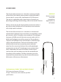
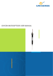
FLOW SENSOR USER MANUAL
1
FLOW SENSOR MANUAL
UNISENSE A/S
Flow sensor manual
Copyright © 2012· Unisense A/S
Version April 2012
TABLE OF CONTENTS
CONGRATULATIONS WITH YOUR NEW PRODUCT! . . . . . . . . . . . . . . . . . . . . . . . . . . . . 1
Support, ordering, and contact information
1
OVERVIEW . . . . . . . . . . . . . . . . . . . . . . . . . . . . . . . . . . . . . . . . . . . . . . . . . . . . . . . . . . . . . . . . . . . . 3
PRECAUTIONS . . . . . . . . . . . . . . . . . . . . . . . . . . . . . . . . . . . . . . . . . . . . . . . . . . . . . . . . . . . . . . . . 4
GETTING STARTED . . . . . . . . . . . . . . . . . . . . . . . . . . . . . . . . . . . . . . . . . . . . . . . . . . . . . . . . . . . 5
Unpacking a new sensor
Polarization
Connecting the microsensor
Pre-polarization
Supply tracer
Calibration
5
5
5
5
6
7
GENERAL USE OF THE FLOW SENSOR . . . . . . . . . . . . . . . . . . . . . . . . . . . . . . . . . . . . . . . . . 9
Mounting of the sensors
Electrical noise
Interference
9
9
9
ADVANCED USE OF THE FLOW SENSORS . . . . . . . . . . . . . . . . . . . . . . . . . . . . . . . . . . . . . 10
STORAGE AND MAINTENANCE . . . . . . . . . . . . . . . . . . . . . . . . . . . . . . . . . . . . . . . . . . . . . . 11
REFERENCES . . . . . . . . . . . . . . . . . . . . . . . . . . . . . . . . . . . . . . . . . . . . . . . . . . . . . . . . . . . . . . . . . 12
WARRANTY AND LIABILITY . . . . . . . . . . . . . . . . . . . . . . . . . . . . . . . . . . . . . . . . . . . . . . . . . . 13
Repair or adjustment
13
TROUBLE SHOOTING . . . . . . . . . . . . . . . . . . . . . . . . . . . . . . . . . . . . . . . . . . . . . . . . . . . . . . . . 14
CONGRATULATIONS WITH YOUR NEW PRODUCT!
Support, ordering, and contact information
If you wish to order additional products or if you encounter any
problems and need scientific/technical assistance, please do not
hesitate to contact our sales and support team. We will respond to
your inquiry within one working day.
E-mail: [email protected]
Unisense A/S
Tueager 1
DK-8200 Aarhus N, Denmark
Tel: +45 8944 9500
Fax: +45 8944 9549
Further documentation and support is available at our website
www.unisense.com.
REPLACEMENT OF SENSORS
Unisense will replace sensors that have been damaged during shipment provided that:
•
The sensors were tested immediately upon receipt in accordance with the delivery note
and the manual
•
The seal is still intact.
•
The sensors are returned to Unisense for inspection within two weeks.
•
The sensors are correctly packed for return to Unisense, in accordance with the note
included in the sensor box.
1
RECOMMENDED AMPLIFIERS
One-channel amplifier: Microsensor Monometer
Multi-channel amplifier: Microsensor Multimeter
2
OVERVIEW
The Unisense flow microsensor is based on a unique principle,
which allows fluid velocity measurements to be performed at
the very tip of a sensor with a tip diameter of 10-50 microns.
The sensor is applicable within several areas of research, e.g.
physiology, hydrology, biotechnology, and environmental sciences
WARNING
Unisense sensors
are neither
intended nor
approved for use
on humans
With its minute tip size the Unisense flow microsensor makes it
possible to make reliable and fast fluid velocity measurements
with a high spatial resolution.
Tracer reservoir
capillaries
LEMO plug
Sensor tip
THIS MANUAL COVERS THE UNISENSE SENSORS
FS20 (outer tip diameter 20-30µm)
FS-spec - Flow sensors with customer specified
specifications.
Cable includes guard
The Unisense flow microsensor is a based on a miniaturized
amperometric hydrogen micro-transducer surrounded by a tracer
gas reservoir, which is closed by a tip membrane. The hydrogen
tracer gas will diffuse out of the tracer reservoir and result in a
build-up of hydrogen around the sensor tip. If the medium is
stagnant, the hydrogen tracer will build up to a relatively high
steady-state concentration. The faster the medium moves
relative to the sensor tip, transporting tracer molecules
away from the sensor tip, the lower the resulting hydrogen
concentration at the tip. The hydrogen tracer concentration
level is detected by the micro-transducer, and the signal
size from the micro-transducer can thus be correlated with
the velocity of the medium. The flow microsensor must be
connected to a picoammeter (e.g. the Unisense Microsensor
Multimeter or Microsensor Monometer).
3
PRECAUTIONS
Particles at the sensor tip
The signal is very sensitive to particles adhering to the tip. Even
small dust grains attached to the tip will create a significant
signal increase due to the associated stagnant water. For this
reason it is recommended that a fine brush is implemented into
the measuring setup, so the sensor tip can be cleaned at regular
intervals.
Direction of flow
The flow sensors are always somewhat directionally sensitive.
This is because it is impossible to build the sensor completely
symmetrically. Thus, you either need to know the direction of flow
in your system and calibrate in the same direction, or you operate
with substantial uncertainties, especially at high velocities.
Calibration of flow sensor
You need a dedicated calibration setup preferable consisting of a
system with stagnant water, which can be moved at well-defined
speeds. Contact Unisense about details and support on this issue.
Hydrogen supply
A source of hydrogen gas must be available for a continuous
flushing of the tracer reservoir (gas consumption approx. 5 ml/
minute). Alternatively, the sensors can be made with a refillable
but closed reservoir for measurements where a source of
hydrogen gas is not available. However, the signal will decrease at
a rate of typically 10%/day due to inevitable leakage, necessitating
re-calibration at regular intervals.
Temperature
Like al other sensors, the flow sensor is temperature sensitive.
4
GETTING STARTED
The signal from the flow sensor is generated in pA. Therefore the
sensor must be connected to a picoampere amplifier, like the
Unisense Microsensor Multimeter.
Unpacking a new sensor
When receiving a new microsensor, remove the shock-absorbing
grey plastic net. Please do not remove the seal and protective
tube before the following steps are successfully completed.
WARNING
Do not remove
seal and protective
plastic tube before
the following steps
are successfully
completed.
Polarization
The signal from the flow sensor is generated in picoampere.
Therefore the sensor must be connected to a polarizing
picoammeter (e.g. a Microsensor Monometer, a Microsensor
Multimeter, or the Unisense PA2000).
Flow sensors should be polarized at +1000 mV. The polarization
voltage is set in the amplifier. For details on how to set and check
the polarization, consult the user manual of the picoammeter
to be used. If you are using a PA2000 amplifier, please check the
polarization voltage before connecting the sensor, since incorrect
polarization may destroy the sensor.
Connecting the microsensor
Connect the LEMO connector to the input terminal. The LEMO
connector contains connections for both reference, guard, and
sensing cathode.
Pre-polarization
When the sensor is not in use, H2 will build up inside the
electrolyte of the hydrogen transducer. This must be removed in
order to obtain a stable zero current as background for calibrations
and measurements. Therefore, a period of polarization is necessary
5
before you can use the sensor. This is called the pre-polarization
period.
Just after connecting the sensor, the signal will be very high and
then drop rapidly over the first few minutes. After that the signal
will drop slowly for up to 1 hour. If the sensor is new or has not
been operated for several days, it must be polarized for at least 1
hour before it can be calibrated and used. After shorter periods
without polarization, the sensor should be polarized until it has
exhibited a stable signal for 10 minutes.
The signal depends on the specific sensor (see the value in the
specifications that came with the sensor).
If the signal does not stabilize or is too high or too low, refer to the
‘Trouble-shooting’ section of this manual.
Supply tracer
If your flow microsensor is of the flow-through type, connect a
tracer source to one of the steel capillaries. The tracer source is a
tank of suitable tracer gas with an outlet valve, which leads the
tracer through a soft tube. By inserting a T-piece with a side-tube,
opening at the bottom of a beaker of water, a suitable pressure
can be obtained. Adjust the outlet flow from the tracer tank
to a level just under the point when bubbles appear from the
side-tube. It is generally best to minimize the length of the tubes
used in the set-up.
If the sensor is of the closed reservoir type with a refill system, start
by refilling the reservoir if necessary. The refill system consists of
two glass tube inlets with a silicone septum and sealed with wax,
which closes the two steel capillaries of the tracer reservoir. To refill
the reservoir, proceed as follows:
Insert a 0.5-mm syringe needle, through both wax plugs
proceeding slightly into the silicone membrane. After piercing
the wax plugs a fresh 0.5-mm syringe needle is carefully inserted
through the hole of each wax plug and pushed through the
silicone membrane. A dry 20-ml syringe is filled with the desired
tracer (e.g. 100% hydrogen) from a tracer source. The tracer
must be dry. The syringe is attached to the needle in one of the
inlets. Atmospheric contamination of the tracer in the syringe
during transfer can be avoided by keeping the nozzle blocked
6
when possible, or by releasing a small tracer flow through the
nozzle when it is not blocked. When the syringe is attached to the
needle, the tracer is slowly injected. Make sure that the reservoir
is actually flushed. This is achieved when a tracer stream flows
from the needle in the other inlet. This can be detected by feeling
the gas stream against the eye or by observing bubbles when a
soap-covered finger is held lightly against the top of the needle.
Be careful not to introduce moisture into the reservoir!
When the reservoir has been flushed with at least 10 ml of the
tracer, remove the syringe and the attached needle. Wait 3
seconds, then remove the needle in the other inlet. The silicone
membrane will now keep the tracer inside the reservoir, but to
make the final gas-tight seal, the wax plugs must be re-melted.
This is done by heating a metal object (e.g. the tips of a pair of
tweezers) and holding it against the outside of the glass inlet, just
long enough for the wax to become clear and liquid. When the
wax hardens, the refill is completed.
When the tracer is present in the reservoir, the signal should
decrease when the water, in which the sensor tip is immersed, is
moved by gently moving the beaker up and down. If the sensor
responds consistently in this fashion, it is functioning correctly.
Calibration
Calibration must be performed after the signal has stabilized
during pre-polarization. Please consult the software manual for
instruction on how to calibrate in the software.
The flow microsensor is placed in a calibration set-up. Such
a set-up consists of a device that allows the sensor tip to be
immersed in a liquid medium, which can be moved at controlled
linear velocities. Alternatively, the sensor tip is moved at controlled
velocities through a stationary medium.
The set-up is activated through a range of known velocities, and
when it has stabilized the signal is logged at each velocity. The
readings are used to produce a calibration curve, through which a
measured signal can be converted into a velocity.
IMPORTANT: small dust particles may adhere to the flow
microsensor tip and strongly influence the signal. If this happens,
IMPORTANT
It is necessary to
perform calibration
and subsequent
measurements in
solutions with the
same temperature
and salinity.
IMPORTANT
Flow microsensors
are not completely
symmetrical, which
means that there
is some directional
sensitivity. Always
calibrate with the
sensor oriented
in the same way
relative to the
direction of flow as
in the system to be
studied
7
remove the particles by carefully brushing the tip with a very fine
paintbrush (the finest type that can be bought for art painting).
The brush is preferably mounted under water with its hairs
pointing up; the sensor tip is cleaned by moving it back and forth
with the micromanipulator controls through the tips of the brush
hairs. If you touch the tip with coarser parts of the brush, the
sensor may break.
Check and repeat calibration at appropriate intervals to ensure
that all measurements can be calibrated to correct velocities. To
minimize the need for calibrations, keep the sensor polarized
between measurements, unless the time between measurements
exceeds several days
The gas permeability of flow microsensor membranes changes
with time, so a change in signal of up to 50% may occur over
months.
If the sensor functions according to the above procedure,
the seal and protective plastic tube can be carefully removed
before making measurements.
8
GENERAL USE OF THE FLOW SENSOR
Flow sensors can be used for a wide variety of measurements (see
www.unisense.com for further information) but they are most
commonly used for monitoring flow in boundary layers between
water and the sea floor, leaves, stones etc. Often they are used
in systems where a high spatial resolution is required or for flow
measurements in water samples.
Mounting of the sensors
During measurements the sensor should be properly mounted in
a stable set-up. Due to the small size of the microsensor tip and
the steepness of flow gradients in many environments, even a few
microns’ displacement of the sensor tip may change its immediate
flow environment. Furthermore, lateral movements of the sensor
while it is in contact with solid substrate may harm the sensor.
Therefore measurements should be performed only in a stabilized
set-up fixed on a sturdy table, free of moving or vibrating devices.
We recommend the Unisense Laboratory Stand LS18 and the
Unisense micromanipulators for this purpose.
IMPORTANT
When the sensor tip
is in contact with a
solid substrate, do
not make lateral
movements of the
microsensor and
avoid disturbing
the microsensor
equipment or table.
Electrical noise
The signal of the microsensor is very small (10-13 to 10-10 amp.).
Although both the amplifiers and the microsensors are very
resistant to electrical noise from the environment, electrical fields
may interfere with the sensor signal. Therefore we recommend
that unnecessary electrical/mechanical equipment is switched off
and the sensor or wires are not touched during measurements and
signal recording.
Interference
The presence of sulphide gas can seriously affect measurements.
The sensitivity to sulfide gas can be as much as 10% of the
hydrogen sensitivity. In addition, exposure to high sulfide gas
concentration can affect the calibration of the hydrogen sensor.
Therefore measurements done in environments with high sulfide
concentrations are not recommended.
IMPORTANT
Closely monitor the
temperature, as
the sensor signal
is very dependent
on temperature.
The temperature
coefficient varies
from sensor to
sensor but is
approximately 2-3
% per oC.
9
ADVANCED USE OF THE FLOW SENSORS
Unisense can construct flow sensors for customer requested
applications at additional costs. The most frequently requested
construction options are described at our web page under flow
sensors specifications.
The options include e.g. customer specified dimensions, response
time, stirring sensitivity, pressure tolerance, flow range and
detection limit. If your specifications for a special flow sensor are
not described at our web page please contact [email protected]
for further options and prices.
Examples of advanced applications
• Measurements of blood flow
• Monitoring bioturbation by measurements of
flow in worm tubes (contact sales@unisense.
com for further details)
10
STORAGE AND MAINTENANCE
Store the sensor in the protective plastic tube used for shipping.
The hydrogen microsensor can be stored with the tip exposed to
water or air. The room in which the hydrogen microsensor is stored
should be dry and not too hot (10-30oC). If the sensor is used
regularly it can be stored polarized and connected to the amplifier.
11
REFERENCES
• Revsbech, N. P., and B. B. Jørgens. 1986.
Micorelectrodes: Their Use in Microbial
Ecology, p. 293-352. In K. C. Marshall (ed.),
Advances in Microbial Ecology, vol. 9.
Plenum, New York.
• Kühl M. Revsbech, NP. 2001 Biogeochemical
microsensors for boundary layer studies.
In: Boudreau BP, Jørgensen BB, editors. The
Benethic boundary layer. New York: Oxford
University press. p180-210.
12
WARRANTY AND LIABILITY
Microsensors are consumable items. The sensors are tested
thoroughly before packaging and shipment.
Warranty for sensors:
N2O sensors: 60 days from shipment.
Standard Oxygen sensors: 180 days from shipment.
All other sensors excluding special sensors: 90 days from shipment.
If, within the above specified period, the sensor(s) fail to perform
according to the specifications, Unisense will replace the sensor(s)
free of charge.
Unisense will only replace dysfunctional sensors if they have
been tested according with the instructions in the manual
upon receipt of the sensor(s).The warranty does not include
repair or replacement necessitated by accident, neglect, misuse,
unauthorized repair, or modification of the product.
Physical damage to the tip of the sensor is not covered by the
warranty.
Liability
In no event will Unisense be liable for any direct, indirect,
consequential or incidental damages, including lost profits, or for
any claim by any third party, arising out of the use, the results of
use, or the inability to use this product.
Repair or adjustment
Sensors and electrodes cannot be repaired. Other equipment
that is not covered by the warranty will, if possible, be repaired
by Unisense with appropriate charges paid by the customer.
In case of return of equipment please contact us for a return
authorization.
For further information please see the documents “Conditions
for Sale and Delivery for Unisense” and “Warranty and Shipping
Information”.
13
TROUBLE SHOOTING
Problem
Possible cause
The calibration response has changed.
A disturbing object is adhered to the sensor tip.
Solution
Carefully brush the sensor tip with a very fine brush,
preferably under water (see section on Calibration). If
the deposits consist of grease, rinse with ethanol before
brushing.
Problem
A high and drifting signa
Possible cause
Solution
Problem
Gas bubbles are present inside the micro-transducer tip
due to short circuit or electrical shock.
Produce degassed water by boiling and subsequent
cooling or by 10 minutes of vacuum treatment. Immerse
the sensor tip for 20 min in the degassed water. Repeated
or prolonged treatment may be necessary
The flow microsensor tip is broken
Possible cause
Solution
Replace the flow microsensor
Problem
The signal is very low
Possible cause
Solution
Problem
Possible cause
14
Contamination of the cathode surface (e.g. by sulfide) or
loss of anode material due to excessive vibrations
Replace the flow microsensor
Signal is unstable or fluctuates when the set-up is touched
or equipment is introduced in the measurement medium.
Electrical disturbance of the sensor through the membrane
Solution
Ground the set-up by connecting the provided blue
grounding cable supplied with the measurement medium.
(If you are measuring in e.g. a sediment, just put the open
wire end in the water column).
Problem
Possible cause
Solution
If you encounter other problems and need scientific/technical assistance, please contact
[email protected] for online support (we will answer you within one workday)
16
17
UNISENSE, DENMARK
www.unisense.com · [email protected]