1
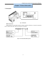
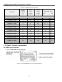
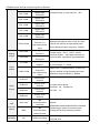
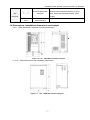
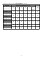
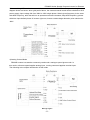
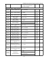
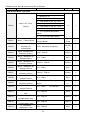
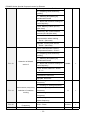
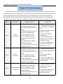
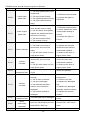
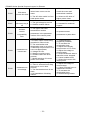
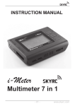
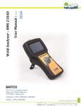
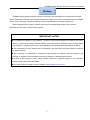
FR200D Series Special Purpose Inverter for Elevator
Preface
FR200D series special purpose inverter for elevator, are developed for Construction Elevator,
Simple Passenger Elevator, and Elevator Machinery, based on the core control arithmetic of FR200
vector control inverters, combined with the control requirements of elevator application.
When debugging the product, please refer to the commissioning guide in this manual,
maintenance can refer to FR200 user manual.
IMPORTANT NOTES
◆To illustrate the details of the products,pictures in this manual based on products with outer
casing or safety cover being removed. When using this product, please be sure to well install
outer casing or covering by the rules, and operating in accordance with the manual contents.
◆ The illustrations in this manual are for illustration only and may vary with different products
you have ordered.
◆ The company is committed to continuous improvement of products, product features will
continue to upgrade, the information provided is subject to change without notice.
◆ If there is any questions when using, please contact our regional agents or our customer
service center:(+86-0755-33067999)
◆For other products, please visit our website. http://www.frecon.com.cn
-1-
FR200D Series Special Purpose Inverter for Elevator
Contents
Preface.................................................................................................................................................................... - 1 Contents................................................................................................................................................................. - 2 Chapter 1 Product Information....................................................................................................................... - 3 1.1 Nameplate...................................................................................................................................................- 3 1.2 FR200D series Special Purpose Inverter Model Selection............................................................. - 4 1.3 Product Terminal Configuration............................................................................................................. - 4 1.4 Dimensions, installation dimensions and weight............................................................................... - 7 Chapter 2 Commissioning guide....................................................................................................................- 9 Chapter 3 Function Parameters................................................................................................................... - 12 3.1 The Basic Function Parameters.......................................................................................................... - 12 Chapter 4 Troubleshooting............................................................................................................................ - 26 -
-2-
FR200D Series Special Purpose Inverter for Elevator
Chapter 1 Product Information
1.1 Nameplate
Fig.1-1 Nameplate
Model Instruction
Model numbers on name plate consist of numbers, symbols, and letters, to express its respective
series, suitable power type, power level and other information.
Figure 1-2 Product Model Naming Rules
-3-
FR200D Series Special Purpose Inverter for Elevator
1.2 FR200D series Special Purpose Inverter Model Selection
Table 1-1 FR200D series model table
Power
Model No.
capacity
KVA
3-Phase:380V,50/60Hz
Rated
Rated
Input
output
current
current
A
A
Applicable motor
kW
HP
Range:-15%~+30%
FR200D-4T-0.7B
1.5
3.4
2.5
0.75
1
FR200D-4T-1.5B
3
5.0
4.2
1.5
2
FR200D-4T-2.2B
4
5.8
5.5
2.2
3
FR200D-4T-4.0B
6
11
9.5
3.7、4
5
FR200D-4T-5.5B
8.9
14.6
13
5.5
7.5
FR200D-4T-7.5B
11
20.5
17
7.5
10
FR200D-4T-011B
17
26
25
11
15
FR200D-4T-015B
21
35
32
15
20
FR200D-4T-018B
24
38.5
37
18.5
25
FR200D-4T-022B
30
46.5
45
22
30
FR200D-4T-030B
40
62
60
30
40
FR200D-4T-037B
57
76
75
37
50
FR200D-4T-045B
69
92
91
45
60
FR200D-4T-055B
85
113
112
55
70
FR200D-4T-075B
114
157
150
75
100
1.3 Product Terminal Configuration
1.3.1 Main Circuit Terminals
a: 0.75~30KW Main Circuit Terminals
Figure 1-3 4.0~30kW Main Circuit Terminal Diagram
-4-
FR200D Series Special Purpose Inverter for Elevator
Table 1-2 Functions of Inverter Main Circuit Terminals
Terminal Label
Description
R/L1、S/L2、T/L3
AC Power Input Terminal, connected to three-phase 380V AC power.
U/T1、V/T2、W/T3
Inverter AC output terminal, connected to three-phase AC motor
(+)、(-)
Respectively to be positive and negative terminal of internal DC bus
Braking resistor connection terminals, one end connected to (+), the
PB
other end of PB.
Ground terminal, connected to the earth.
1.3.2 Control Circuit Terminals
Figure 1-4 Control Terminals Diagram
Table 1-3 FR200D Inverter Control Circuit Terminal Functions
Type
Terminal
Symbol
Terminal Name
Description
Output +10V Power Supply, Maximum
+10V-GND
+10V Power
Output Current: 10mA. Generally use for
Supply
power supply of external potentiometer,
resistance range of potentiometer: 1~5kΩ
Output +24V power supply, generally use for
Power
+24V-COM
24V Power Supply
Supply
power supply of digital input/output terminal
and external sensor, maximum output
current: 200mA.
Factory default in connection with
PLC
External Power
Input Terminal
+24V,when using an external signal to drive
DI1~DI7, PLC need to be connected to
external power, and disconnected with +24V
power terminal.
AI1-GND
Analog
Input
AI2-GND
AI3-GND
Digital
DI1- COM
Analog Input
Input Range: DC 0~10V/0~20mA,
Terminal 1
selected by AI1、AI2 toggle switches on
control board. Input Impedance:250kΩ for
Analog Input
Terminal 2
voltage input, 250Ω for current input.
Analog Input
Input voltage range: DC -10~+10V
Terminal 3
Input Impedance: 250kΩ
Digital Input
Maximum input frequency: 200Hz
-5-
FR200D Series Special Purpose Inverter for Elevator
Input
Terminal 1
DI2- COM
DI3- COM
DI4- COM
DI5- COM
DI6- COM
Input Impedance: 2.4kΩ
Voltage Range of level-input:9V~30V
Digital Input
Terminal 2
Digital Input
Terminal 3
Digital Input
Terminal 4
Digital Input
Terminal 5
Digital Input
Terminal 6
Digital Input
DI7/HI-COM
Besides the features of DI1~DI6, DI7 also
Terminal 7 or
high-speed pulse
input
Analog
Output
AO1-GND
AO2-GND
Y1-COM
Digital
Output
Analog Output
Terminal 1
Analog Output
Terminal 2
Open Collector
Output 1
Output 2or
high-speed pulse
output
R1A-R1C
Relay
Output
R1B-R1C
R2A-R2C
R2B-R2C
input. Maximum input frequency: 100kHz.
Output range:DC 0~10V/0~20mA,
selected by A01、A02 toggle switches on
control board. Impedance required≥10kΩ
Voltage Range: 0~24V
Current Range: 0~50mA
Open Collector
Y2/HO-COM
can be the channel of high-speed pulse
Apart from Y1 characteristics, Y2 also can
be the channel of high-speed pulse input.
Maximum output frequency: 100kHz.
normal open
terminal
normal close
Contact driving ability:
terminal
AC250V,3A,COSØ=0.4。
normal open
DC 30V,1A
terminal
normal close
terminal
485
485
485+-485-
Terminals
Commun
ication
Communication
GND
Speed:
4800/9600/19200/38400/57600/115200bps.
485
RS485 toggle switch on control board,
Communication
setting the terminal matching-resister
Shield Ground
Shielded
PE
Shield Grounding
-6-
It’s use for grounding the shield of
terminal-wire
FR200D Series Special Purpose Inverter for Elevator
When connected to operation board, the
Aid
External Keyboard
longest communication distance is up to
Interface
50m, adopt the standard network cable
(RJ45)
Interface
UP/DOWNL
Parameter Copy
OAD
Card Interface
1.4 Dimensions, installation dimensions and weight
a:4.0~15kW Dimensions and wall mounting dimensions
Figure 1-5 0.75~15kW Wall Installation Diagram
b: 18.5~75kW Dimensions and installation dimensions
Figure 1-6 18.5~30kW Wall mounting diagram
-7-
FR200D Series Special Purpose Inverter for Elevator
Table 1-4 Wall Mounting Size Table
Model No.
Dimensions and installation size(mm)
W
W1
H
H1
D
Installati
Weight
on
(Kg)
Aperture
FR200D-4T-0.7B
FR200D-4T-1.5B
116.6
106.6
186.6
176.6
168
4.5
2.2
146
131
249
236
177
5.5
3.2
198
183
300
287
185
5.5
5.4
255
176
459
443
220
7
15.5
270
130
590
572
260
7
27.5
357
230
590
572
260
7
37
FR200D-4T-2.2B
FR200D-4T-4.0B
FR200D-4T-5.5B
FR200D-4T-7.5B
FR200D-4T-011B
FR200D-4T-015B
FR200D-4T-018B
FR200D-4T-022B
FR200D-4T-030B
FR200D-4T-037B
FR200D-4T-045B
FR200D-4T-055B
FR200D-4T-075B
-8-
FR200D Series Special Purpose Inverter for Elevator
Chapter 2 Commissioning guide
FFR200D series Inverter developed special for elevator industry, controlmodes as below:
1) Multi-stage Speed Control Mode
Multi-stage speed control is a common mode in elevator application,whose characteristic is strong
anti-jamming ability, good suitability and easy to be realized. But in typical multi-stage speed control
when different speed combinations are switched, the acceleration and deceleration curves are the
same, and they affects each other, so users can not attend everything during actual adjustment.
FR200D series inverter has been specially designed to solve this problem: each speed combination
corresponds to different acceleration and deceleration curve,which make adjustment easier for users.
2) Inspection Running
FR200-D inverter has internal inspection running mode when it’s under multi-stage speed control
mode, which has been designed according to the characteristics of the elevator inspection running. if
inspection input is effective, inspection running speed will be adjusted by the setting of function code.
For example, FR200-D will run at the target frequency of multi-stage speed 3, and acceleration time is
decided by the corresponding time curve of multi-stage speed 3. During stall, if inspection input signal
is canceled first, the system will decelerate to 0 during thedeceleration time of multi-stage speed 3 until
forward or reverse running command is canceled.
-9-
FR200D Series Special Purpose Inverter for Elevator
If forward or reverse running command is canceled directly during inspection running,
FR200D will stop output immediately, as shown in the following figure.
3) Power Failure Emergency Running
In the using of elevator, if the power is cut suddenly, passengers may be kept in the cage.
FR200-D series inverters can support emergency UPS power running, Both the main circuit of
FR200D and the working are powered by UPS.
- 10 -
FR200D Series Special Purpose Inverter for Elevator
When receiving ARD terminal command, inverter auto switched to ARD mode operation. Logic
diagram shown as below, when grid power failure, the external control board will be switched to UPS
power supply, input voltage fall from 380V to 230V single phase. Switch given frequency is the same
with ARD frequency, after that will run as operation terminal command, keep ARD frequency, please
shield the input default phase of inverter right now, inverter undervoltage detection point switched to
190V.
4) Analog Control Mode
FR200D inverter has another commonly used mode: analogue speed given mode. In
this mode, reference speed applies analog input, running command applies terminal input.
The following is the simple introduction of this mode.
Wirings Figure
- 11 -
FR200D Series Special Purpose Inverter for Elevator
Chapter 3 Function Parameters
3.1 The Basic Function Parameters
Table 3-1 Basic Function Parameters
Function
Code
Name
Descriptions
Default
Attrib
Value
ute
0
×
0
×
F00 Group: System Parameters
F00.00
User Password
0~65535
0:Null
1:Factory Reset(Excluding motor
parameters)
2: Clear the record information of
F00.04
Default Value Control
fault
3:Backup user’s current
parameters
4:User’s backup parameters were
restored
F01 Group: Frequency Given
F01.08
F01.09
F01.10
Maximum Frequency
(Fmax)
Upper Limit
Frequency(Fup)
Lower Limit
Frequency(Fdown)
Given frequency lower
F01.11
F01.12
20.00~600.00Hz
Fdown~Fmax
0.00~Fup
1:After running time of lower limit
control of lower limit
frequency, it will run on speed of 0.
limit frequency
z
50.00H
z
×
×
0.00Hz
×
0
×
60.0s
×
0
×
0:Run by the lower frequency
than the frequency
Running time of lower
50.00H
0.0~6000.0s
F02 Group: Control of Run/Stop
0:Operation Panel(LED off)
F02.00
Command Source
Selection of Run/Start
1:External Terminal(LED on)
2:Computer Communications
( LED flash)
F03 Group: Acceleration/Deceleration Time
F03.00
Acceleration Time1
0.0~6000.0s
15.0s
△
F03.01
F03.02
F03.03
F03.04
Deceleration Time1
Acceleration Time2
Deceleration Time2
Acceleration Time3
0.0~6000.0s
0.0~6000.0s
0.0~6000.0s
0.0~6000.0s
15.0s
4.0s
4.0s
4.0s
△
△
△
△
- 12 -
F03.05
F03.06
F03.07
Deceleration Time3
Acceleration Time4
Deceleration Time4
F03.10
Accel/Decele curve
F03.11
F03.15
F03.16
F03.17
S curve Time1
S curve Time2
S curve Time3
S curve Time4
FR200D Series Special Purpose Inverter for Elevator
0.0~6000.0s
4.0s
△
0.0~6000.0s
20.0s
△
0.0~6000.0s
20.0s
△
0: Linear Accel/Decel
1
×
1: S-curve Accel/Decel
1.0s
0.0~6000.0s
×
0.0~6000.0s
1.0s
×
0.0~6000.0s
1.0s
×
0.0~6000.0s
1.0s
×
F04 Group: Digital Input Terminals
F04.00
F04.01
F04.02
F04.03
F04.04
F04.05
F04.06
Function of terminal
DI1
Function of terminal
DI2
Function of terminal
DI3
Function of terminal
DI4
Function of terminal
DI5
Function of terminal
DI6
Function of terminal
DI7
0: No function
1: Running forward (FWD)
2: Running reverse (REV)
3: Three-wire control
4: JOG forward
5: JOG reverse
6: Coast to stop
7: Fault reset (RESET)
8: Running suspended
9: External fault input
10: Terminal UP
11: Terminal DOWN
12: UP/DOWN (including ∧/∨
key) adjustment clear
13: Multi-step frequency terminal 1
14: Multi-step frequency terminal 2
15: Multi-step frequency terminal 3
16: Multi-step frequency terminal 4
17: Accel/Decel time determinant 1
18: Accel/Decel time determinant 1
19: Accel/Decel disabled(ramp
stop not inclusive)
20: Switch to auxiliary speed
setting
21: PLC status reset
22: Simple PLC paused
23: Simple PLC paused
24: PID adjustment direction
25: PID integration paused
26: PID parameter switch
27: Swing frequency pause(output
the currentfrequency)
28: Swing frequency reset(output
the central frequency)
29: Run command switched to
keypad contro
30: Run command switched to
terminal control
31: Run command switched to
communication control
32: Count input
33: Count clear
34: Length count
35: Length clear
36: DC brake input command at
stop
- 13 -
1
×
2
×
13
×
14
40
×
41
×
6
×
FR200D Series Special Purpose Inverter for Elevator
37: Special drive enable
40: Elevator inspection signal
41: Elevator emergency signal
F05 Group: Digital Output Terminal
F05.00
F05.01
F05.02
Y1 Output Function
Selection
Y2 Output Function
Selection
Relay R1 Output
Function Selection
0: No output
1: Drive is running
2: Fault output
3: Frequency-level detection
FDT1 output
4: Frequency-level detection
FDT2 output
5: Drive in 0Hz running 1(no
output at stop)
6: Drive in 0Hz running 2(output
at stop)
7: Upper limit frequency attained
8: Lower limit frequency attained
9: Frequency attained
10: Inverter is ready to work
11: Drive (motor) overloaded
alarm
12: Inverter overheat warning
13: Current running time attained
14: Accumulative power-on time
attained
15: Consecutive running time
attained
16: PLC cycle completed
17: Set count value attained
18: Designated count value
attained
19: Length attained
2
×
3
×
21
×
1
×
2
×
1
×
20: Under load alarm
21: Braking output
F07 Group: Analog and Pulse Output
F07.00
F07.01
AO1 Output Function
Selection
AO2 Output Function
Selection
0:No Output
1:Output Frequency
2:Set Frequency
3:Output Current(Inverter Rated
Current)
4:Output Voltage(Inverter Rated
Voltage)
5:Output Power
Y2/HO Output Function
F07.02
Selection
(When used as HO)
6:Bus Voltage
7:+10V
8:Keyboard Potentiometer
9:AI1
10:AI2
11:AI3
12:HI Input(100.0%corresponds
- 14 -
FR200D Series Special Purpose Inverter for Elevator
100.00kHz)
13:Output Torque(Absolute
Value of the Torque)
F08 Group: Motor 1 Basic Parameters
F08.01
Motor 1 Rated Power
0.10~600.00kW
F08.02
Motor 1 Rated Voltage
60~660V
F08.03
Motor 1 Rated Current
0.1~1500.0A
F08.04
F08.05
F08.06
F08.07
F08.08
F08.09
F08.10
F08.11
F08.12
Motor 1 Rated
Motor 1 Rated
Motor 1 Wirings
Motor 1 Rated Power
Asynchronous Motor 1
Stator Resistance R1
Asynchronous Motor 1
Rotor Resistance R2
Asynchronous Motor 1
Leakage Inductance
Asynchronous Motor 1
Mutual Inductance
Asynchronous Motor 1
No-load Field Current
fixed
Type
fixed
Type
fixed
Type
fixed
Type
fixed
0:丫
Type
1:Δ
fixed
0.50~0.99
Factor
0.001~65.535Ω
0.001~65.535Ω
0.001~65.535mH
0.1~6553.5mH
0.1~1500.0A
Type
fixed
Type
fixed
Type
fixed
Type
fixed
Type
fixed
Type
fixed
×
×
×
×
×
×
×
×
×
×
×
×
1
field-weakeningcoefficie
nt
0.0~100.0
87%
×
0.0~100.0
75%
×
0.0~100.0
70%
×
0
×
1
Asynchronous Motor
F08.14
1~30000
Rotational Speed
Asynchronous Motor
F08.13
20.00~Fmax
Frequency
Type
1
field-weakeningcoefficie
nt 2
Asynchronous Motor
F08.15
1
field-weakeningcoefficie
nt 3
0:Null
F08.30
Parameters
Self-identification
1:Asynchronous Motor Static
Self-identification
2:Asynchronous Motor Rotation
- 15 -
FR200D Series Special Purpose Inverter for Elevator
Self-identification
F09 Group: Motor 1VF Curve
0:Straight Line V/F
1:Multipoint V/F
2:1.2th power of the V/F curve
3:1.4th power of the V/F curve
F09.00
Motor 1VF Curve
4:1.6th power of the V/F curve
Setting
5:1.8th power of the V/F curve
3
×
6:2.0th power of the V/F curve
7:VF Completed Separation
Mode
8:VF Semi-separation Mode
F09.01
Motor 1 Torque Boost
0.0~30.0%
0.0%:(Auto
Torque Boost)
Motor 1 Cut-off
F09.02
frequency of
0.00~Maximum Frequency
Torque-Boost
F09.03
F09.04
F09.05
F09.06
F09.07
F09.08
F09.09
F09.10
F09.11
F09.12
F09.13
F09.14
Motor 1MultipointV/F
frequency points1
Motor 1 Multipoint VF
Voltage Points 1
Motor 1 Multipoint V/F
frequency points2
Motor 1 Multipoint VF
Voltage Points 2
Motor 1 Multipoint V/F
frequency points3
Motor 1 Multipoint VF
Voltage Points 3
Motor 1 Multipoint V/F
frequency points4
Motor 1 Multipoint VF
Voltage Points 4
VF Slip Compensation
Gain
VF Stator Voltage-drop
Compensation Gain
VF Excitation
Compensation Gain
VF Oscillation
Suppression Gain
0.00~F09.05
0.0~100.0
F09.03~F09.05
0.0~100.0
F09.05~F09.09
0.0~100.0
F09.07~Rated Frequency of
Motor
0.0~100.0
Type
Fixed
50.00H
z
△
0.00Hz
△
0.0%
△
0.00Hz
△
0.0%
△
0.00Hz
△
0.0%
△
50.00H
z
△
100.0%
△
0.0~300.0%
0.0%
△
0.0~200.0%
100.0%
△
0.0~200.0%
100.0%
△
0.0~300.0%
0.0%
△
- 16 -
Ue=100.0%
△
FR200D Series Special Purpose Inverter for Elevator
F11 Group: Fault and Protection
F11.00
F11.01
Control of Overcurrent
Stall
Protection current of
Overcurrent Stall
0:Null
1: Overcurrent Stall Mode 1
1
×
150.0%
×
0.0~6000.0s (Mode 1 is Active)
5.0s
△
0.1~100.0%
3.0%
△
0.010s
△
1
×
130.0%
×
3.0%
△
0.010s
△
03000
×
00000
×
2: Overcurrent Stall Mode 2
100.0~200.0%
Frequency Fall Time of
F11.02
Constant Speed
Overcurrent Stall
F11.03
F11.04
F11.05
F11.06
F11.07
F11.08
Overcurrent Stall Mode
2 Proportion Coefficient
Overcurrent Stall Mode
2 Integral Time
Control of Overvoltage
Stall
Voltage of Overvoltage
Stall
Overvoltage Stall Mode
2 Proportion Coefficient
Overvoltage Stall Mode
2 Integral Time
0.000~1.000s (0.000:Integral
Invalid)
0:Null
1: Overvoltage Stall Mode 1
2: Overvoltage Stall Mode 2
120.0~150.0%
0.1~100.0%
0.000~1.000s (0.000:Integral
Invalid)
Ones: Bus Undervoltage
Protection(Err07)
0:Reporting faults and freely
parking
1:Alarming and parking by
deceleration mode
2:Alarm and continue running on
fault frequency
F11.10
Selection of failsafe
action 1
3:Protection Invalid
Tens: Input Phase-protection
(Err09) (like ones)
Hundreds: Output
Phase-protection (Err10) (like
ones)
Thousands: Motor Overload
Protection (Err10) (like ones)
Myriabit: Inverter Overload
Protection(Err12)(like ones)
F11.11
Selection of failsafe
Ones: External Input
- 17 -
FR200D Series Special Purpose Inverter for Elevator
action 2
Failure-protection(Err13)
0:Reporting faults and freely
parking
1:Alarming and parking by
deceleration mode
2:Alarm and continue running on
fault frequency
Tens: Memory Failure (Err15)
(like ones)
Hundreds: 485 communication
timeout (Err18) (like ones)
Thousands: PID feedback
disconnection when running
(Err19)(like ones)
Myriabit: running time arrives
(Err20)(like ones)
Ones: Disconnection Fault of
Temperature Sensor(Err24)
0:Reporting faults and freely
parking
1:Alarming and parking by
F11.12
Selection of failsafe
action 3
deceleration mode
2:Alarm and continue running on
00000
×
0
×
0.00~Fmax
0.00Hz
×
30.0~300.0s
60.0s
×
fault frequency
Tens: Inverter load-lost(Err25)
(0~3)
Hundreds: Reserved
Thousands: Reserved
Myriabit: Reserved
0:Running on current setting
frequency
1:Running on setting frequency
When failure, frequency
F11.14
selection of continue
running
2:Running on upper-limit
frequency
3:Running on lower-limit
frequency
4:Running on abnormal
spare-frequency
F11.15
F11.17
Abnormal Alternate
Frequency
Protection time of Motor
- 18 -
FR200D Series Special Purpose Inverter for Elevator
Overload
Ones: selection of detection
0:always detection
1:detection only when constant
speed
F11.18
Selection of Overload
Pre-warning
Tens: condition selection of
00
×
130.0%
×
5.0s
×
50.0~100.0℃
70.0℃
×
5.0~100.0%
20.0%
×
5.0s
×
1
×
5.0s
△
0
×
0
×
1.0s
×
0
×
30.0%
△
100.0%
△
detection
0:responds to rated current of
motor
1:responds to rated current of
inverter
F11.19
F11.20
F11.21
F11.22
F11.23
Detectable Level of
Overload Pre-alarm
Detectable Time of
Overload Pre-alarm
Pre-alarm Temperature
of Inverter Overheat
Detectable Level of
load-loss
Detectable Time of
load-loss
Operation selection of
F11.24
instantaneous power
failure
20.0~200.0%
0.1~60.0s
0.1~60.0s
0:Null
1:Valid
Frequency deceleration
F11.25
time of instantaneous
0.0~6000.0s
power failure
F11.26
F11.27
F11.28
Selection control of fast
0:Prohibit
current-limit
1:Permit
Auto-Reset Times of
failure
Auto-Reset Interval of
failure
During the fault
0~20
0.1~100.0s
0:No action
auto-resetting,program
F11.29
Of switch output
terminal , is action
1:Action
selection of output fault
Group F12: Multi-Reference and Simple PLC Function
F12.00
-100.0~100.0%
Reference 0
F12.01
Reference 1
-100.0~100.0%
- 19 -
FR200D Series Special Purpose Inverter for Elevator
F12.02
Reference 2
-100.0~100.0%
0.0%
△
F12.03
Reference 3
-100.0~100.0%
0.0%
△
U00 Group: Status Monitoring
U00.00
Output Frequency
0.00~Fup
0.00Hz
⊙
U00.01
Setting Frequency
0.00~Fmax
0.00Hz
⊙
0~660V
0.0V
⊙
0.0~3000.0A
0.0A
⊙
-3000.0~3000.0kW
0.0kW
⊙
0~60000rpm
0rpm
⊙
0~1200V
0V
⊙
0.00~Fup
0.00Hz
⊙
U00.02
U00.03
Actual value of output
voltage
Actual value of output
current
U00.04
Output Power
U00.05
Output Rotation-rate
U00.06
DC Bus Voltage
U00.07
Synchronization
Frequency
U00.08
PLC Stage
U00.09
Program Running Time
1
⊙
0.0s(h)
U00.10
PID Given
⊙
0~60000
0
U00.11
PIDArithmetic Feedback
⊙
0~60000
0
⊙
U00.12
DI1~DI5 Input Status
DI5 DI4 DI3 DI2 DI1
U00.13
DI6~DI7 Input Status
DI7 DI6
00000
⊙
00
U00.14
Digital Output Status
⊙
R2 R1 Y2 Y1
0000
U00.15
⊙
AI1 Input
0.0~100.0%
0.0%
⊙
U00.16
AI2 Input
0.0~100.0%
0.0%
⊙
U00.17
AI3 Input
-100.0~100.0%
0.0%
⊙
0.0~100.0%
0.0%
⊙
0.00kHz
⊙
U00.18
Keyboard Potentiometer
Input
1~15
0.0~6000.0s(h)
U00.19
HI Pulse Input Frequency
U00.20
A01 Output
0.0~100.0%
0.0%
⊙
U00.21
A02 Output
0.0~100.0%
0.0%
⊙
0.00~100.00kHz
0.00kHz
⊙
-40.0℃~120.0℃
0.0℃
⊙
U00.22
U00.23
HO Pulse Output
Frequency
Temperature of Inverter
Module
0.00~100.00kHz
U00.24
The Power-on Time
0~65535min
0min
⊙
U00.25
The Running Time
0~6553.5min
0.0min
⊙
0~65535h
0h
⊙
Cumulative Running Time
0~65535h
0h
⊙
U00.28
Actual Count Value
0~65535
0
⊙
U00.29
Actual Length Value
0~65535m
0m
⊙
U00.30
Line Speed
U00.26
U00.27
Cumulative Power-on
Time
0~65535m/min
- 20 -
0m/Min
FR200D Series Special Purpose Inverter for Elevator
U00.31
Output Torque
0.0~300.0%
0.0%
⊙
0
⊙
U01 Group: Failure Record
Err00:No Fault
Err01:Accelerated Overcurrent
Err02:Decelerated Overcurrent
Err03:Constant Speed
Overcurrent
Err04:Accelerated Overvoltage
Err05:Decelerated Overvoltage
Err06:Constant Speed
Overvoltage
Err07:Bus Undervoltage
Protection
Err08:Short Circuit Protection
Err09:Input Open Phase
Err10:Output Open Phase
Err11:Motor Overload
Err12:Inverter Overload
Err13:Fault protection of
external input
Err14:Overheat
U01.00
Current Fault Category
Err15:Memory Failure
Err16:Cancel Autotuning
Err17:Autotuning Failure
Err18:485 Communication
Timeout
Err19:PID feedback
disconnection on runtime
Err20:running time arrives
Err21:Parameter Upload Error
Err22:Parameter Download
Error
Err23:Braking Unit Failure
Err24:Disconnection fault of
temperature sensor
Err25:Lose-load failure/alarm of
Inverter
Err26:with-wave current limit
fault
Err27:Soft-start relay unclosed
Err28:EEPROM Version
- 21 -
FR200D Series Special Purpose Inverter for Elevator
Incompatible
Err29:Instantaneous overcurrent
Err30:Instantaneous
overvoltage
U01.01
U01.02
U01.03
U01.04
U01.05
U01.06
U01.07
U01.08
U01.09
U01.10
U01.11
U01.12
U01.13
U01.14
Output frequency of the
current fault
Output current of the
current fault
c of the current fault
Cumulative runtime of
the current fault
Former one fault
category
Output frequency of the
former one fault
Output current of the
former one fault
Bus Voltage of the former
one fault
Cumulative runtime of
the former one fault
Former two fault
categories
Output frequency of the
former two faults
Output current of the
former two faults
Bus Voltage of the former
two faults
Cumulative runtime of
the former two faults
H00 Group: Elevator Special Group
H00.00
0.0A
⊙
0~1200V
0V
⊙
0~65535h
0h
⊙
Like the latest one fault record
0
⊙
0.00Hz
⊙
0.0A
⊙
0~1200V
0V
⊙
0~65535h
0h
⊙
Like the latest one fault record
0
⊙
0.00Hz
⊙
0.0A
⊙
0~1200V
0V
⊙
0~65535h
0h
⊙
1
×
0.0~3000.0A
0.00~Fup
0.0~3000.0A
0.00~Fup
0.0~3000.0A
0: Null
1: Valid
Brake Open Delay
Start Frequency
H00.05
⊙
Enable
H00.02
H00.04
0.00Hz
Special Inverter Function
H00.01
H00.03
0.00~Fup
Start Frequency Holding
Time
Brake Release Delay
Brake Open Frequency
(Rising)
0.00~10.00s
0.00s
×
5.00Hz
×
0.00~10.00s
0.00s
×
0.00~10.00s
0.20s
×
3.00Hz
×
0.00~10.00Hz
0.00~10.00Hz
- 22 -
FR200D Series Special Purpose Inverter for Elevator
H00.06
H00.07
H00.08
H00.09
H00.10
Brake Release Frequency
(Rising)
Brake Open Frequency
(Falling)
Brake Release Frequency
(Falling)
Brake Open Current
Brake Open Frequency
Holding Time
0.00~10.00Hz
3.00Hz
×
0.00~10.00Hz
3.00Hz
×
0.00~10.00Hz
3.00Hz
×
0.0~100.0%
40.0%
△
0.00~10.00s
0.30s
×
0
×
0.00~50.00Hz
20.00Hz
△
0.00~50.00Hz
20.00Hz
△
1
×
0.00~10.00s
0.20s
×
0.00~10.00s
0.10s
×
1
×
0.00s
×
5.00Hz
×
0.00~10.00s
0.00s
×
0.00~10.00s
0.20s
×
0.00~10.00Hz
3.00Hz
×
0.00~10.00Hz
3.00Hz
×
0.00~10.00Hz
3.00Hz
×
0:open according to frequency
H00.11
Brake Open Type
1:open according to frequency
and current
H00.12
Emergency Operation
Frequency
Overhaul Operation
H00.13
Frequency
Emergency Signal
H00.14
H00.15
H00.16
Processing
Torque output delay
Running contactor release
delay
0: Elevator no run
1: UPS Power-on and run
3.2 H00 group function code detailed explanation
H00.00
Special Inverter
0:Null
Function Enable
1:Valid
0:Null
Standard Machine
1:Valid
Special Purpose Inverter for Elevator, H00 group parameter is valid.
H00.01
Brake Open Delay
0.00~10.00s
H00.02
Start Frequency
0.00~10.00Hz
H00.03
H00.04
H00.05
H00.06
H00.07
Start Frequency
Holding Time
Brake Release Delay
Brake Open
Frequency (Rising)
Brake Release
Frequency (Rising)
Brake Open
Frequency (Falling)
- 23 -
FR200D Series Special Purpose Inverter for Elevator
Brake Release
0.00~10.00Hz
H00.08
Frequency (Falling)
H00.09
Brake Open Current
3.00Hz
×
0.0~100.0%
40.0%
△
0.00~10.00s
0.30s
×
0.00~10.00s
0.20s
×
0.00~10.00s
0.20s
×
Brake Open
H00.10
Frequency Holding
Time
H00.15
H00.16
Torque output delay
Running
contactor
release delay
Setting function code H00.01~H00.10 can well adjust the comfortable of elevators run/stop,
exactly meaningof every function code shown as below:
H00.05(Brake Open Frequency (Rising))、H00.06(Brake Release Frequency (Rising)) and
H00.07(Brake Open Frequency (Falling))、H00.08(Brake Release Frequency (Falling)) have the same
meaning, rising group use for frequency adjusting on FWD, falling group use for frequency adjusting
on REV.
0: open according to frequency
H00.11
Brake Open Type
1: open according to frequency
0
×
and current
0:Open according to frequency
Criteria for judging the brake opening is inverters output reach to the setting frequency of H00.05
(rising) or H00.07 (falling), and then open the brake by setting time of H00.01 (Brake Open Delay).
1: Open according to frequency and current
- 24 -
FR200D Series Special Purpose Inverter for Elevator
Criteria for judging the brake opening is inverters output reach to the setting frequency of H00.05
(rising) or H00.07 (falling), meanwhile, inverter current reach H00.09 (brake open current) setting
value.
H00.12
Emergency Operation
0.00~50.00Hz
20.00Hz
△
Frequency
When emergency signal input, inverters will enter the emergency operating condition, operating
frequency is the setting value of function code, on emergency operating status, inverters will choose
acce/dece time 4 as the current acce/dece time.
H00.13
Overhaul Operation
0.00~50.00Hz
20.00Hz
Frequency
When overhaul signal input, inverter will run according to the overhaul operation frequency.
△
0: Elevator no run
Emergency Signal
1
×
Processing
1: UPS Power-on and run
0: Elevator no runs
When there is the emergency signal input, inverter no output.
1: UPS Power-on and run
When there is emergency signal input, inverter powered by UPS and output on emergency
frequency.
H00.14
- 25 -
FR200D Series Special Purpose Inverter for Elevator
Chapter 4 Troubleshooting
FR200D inverter provides a number of warning information and protection, when a fault occurs,
the protective function is activated, the inverter will stop output, inverter fault relay contact, and in the
inverter displays the fault code on the display panel. Before seeking service user can press the
self-examination tips in this section, analyze problems, and identify solutions. If the problem still
cannot be excluded, seek services, or contact the dealer you purchase the inverter with my company.
Display
Fault Name
Possible Causes
1: The output circuit is
grounded or short circuited.
2: The acceleration time is too
short.
3: Manual torque boost or V/F
curve is not appropriate.
Err01
Accel
overcurrent
4: The voltage is too low.
5: The startup operation is
performed on the rotating
motor.
6: A sudden load is added
during acceleration.
7: The AC drive model is of too
small power class.
1: The output circuit is
grounded or short circuited.
2: The deceleration time is too
Err02
Decel
overcurrent
short.
3: The voltage is too low.
4: A sudden load is added
during deceleration.
5: The braking unit and braking
resistor are not installed.
1: The output circuit is
grounded or short circuited.
Err03
Constant-speed
overcurrent
2: The voltage is too low.
3: A sudden load is added
during operation.
4: The AC drive model is of too
small power class.
- 26 -
Solutions
1: Eliminate external faults.
2: Increase the acceleration
time.
3: Adjust the manual torque
boost or V/F curve.
4: Adjust the voltage to
normal range.
5: Select rotational speed
tracking restart or start the
motor after it stops.
6: Remove the added load.
7: Select an AC drive of
higher power class
1: Eliminate external faults.
2: Increase the deceleration
time.
3: Adjust the voltage to
normal range.
4: Remove the added load.
5: Install the braking unit and
braking resistor.
1: Eliminate external faults
2: Adjust the voltage to
normal range.
3: Remove the added load
4: Select an AC drive of
higher power class.
FR200D Series Special Purpose Inverter for Elevator
1: The input voltage is too high.
2: An external force drives the
Err04
Accel
overvoltage
motor during acceleration.
3: The acceleration time is too
short.
4: The braking unit and braking
resistor are not installed.
1: The input voltage is too high.
2: An external force drives the
Err05
Decel
overvoltage
motor during deceleration.
3: The deceleration time is too
short.
4: The braking unit and braking
resistor are not installed.
Err06
Constant-speed
overvoltage
1: The input voltage is too high
2: An external force drives the
motor during deceleration.
1: Adjust the voltage to
normal range.
2: Cancel the external force
or install a braking resistor.
3: Increase the acceleration
time.
4: Install the braking unit and
braking resistor.
1: Adjust the voltage to
normal range.
2: Cancel the external force
or install the braking resistor.
3: Increase the deceleration
time.
4: Install the braking unit and
braking resistor.
1: Adjust the voltage to
normal range.
2: Cancel the external force
or install the braking resistor.
1: Instantaneous power failure
occurs on the input power
supply.
2: The AC drive's input voltage
is not within the allowable
Err07
Bus
undervoltage
range.
3: The bus voltage is abnormal.
4: The rectifier bridge and buffer
resistor are faulty.
1: Reset the fault.
2: Adjust the voltage to
normal range.
3: Contact the agent or
Frecon.
5: The drive board is faulty.
6: The main control board is
faulty.
1: The output circuit is
grounded or short circuited.
2: The connecting cable of the
motor is too long.
Err08
Short circuit
3: The module overheats.
4: The internal connections
become loose.
5:The main control board is
faulty
6: The drive board is faulty.
- 27 -
1: Eliminate external faults.
2: Install a reactor or an
output filter.
3: Check the air filter and the
cooling fan.
4: Connect all cables
properly.
5: Contact the agent or
Frecon.
FR200D Series Special Purpose Inverter for Elevator
7: The inverter module is faulty.
1: The three-phase power input
is abnormal.
Err09
Power input
2: The drive board is faulty.
phase loss
3: The lightening board is faulty.
4: The main control board is
1: Eliminate external faults.
2: Contact the agent or
FRECON.
faulty.
1: The cable connecting the AC
drive and the motor is faulty.
Err10
Power output
phase loss
2: The AC drive's three-phase
outputs are unbalanced when
the motor is running.
3: The drive board is faulty.
4: The module is faulty.
Err11
Err12
Err13
Err14
Err15
Motor overload
Inverter
overload
External
equipment fault
Module
overheat
EEPROM
read/write fault
Motor
Err16
auto-tuning
cancelled
Err17
Motor
1: Eliminate external faults.
2: Check whether the motor
Three-phase winding is
normal.
3: Contact the agent or
Frecon.
1: F11-17 is set improperly.
1: Set F11-17 correctly.
2: The load is too heavy or
2: Reduce the load and
locked-rotor occurs on the
check the motor and the
motor.
mechanical condition.
3: The AC drive model is of too
3: Select an AC drive of
small power class.
higher power class.
1: The load is too heavy or
1: Reduce the load and
locked-rotor occurs on the
check the motor and
motor.
mechanical condition.
2: The AC drive model is of too
2: Select an AC drive of
small power class.
higher power class.
1: External fault signal is input
via DI.
Reset the operation.
1: The ambient temperature is
1: Lower the ambient
too high.
temperature.
2: The air filter is blocked.
2: Clean the air filter.
3: The fan is damaged.
3: Replace the damaged
4: The thermally sensitive
fan.
resistor of the module is
4: Replace the damaged
damaged.
thermally sensitive resistor.
5: The inverter module is
5: Replace the inverter
damaged.
module.
The EEPROM chip is damaged.
Replace the main control
board.
Since the identification process,
Press STOP / RST key to
press STOP / RST key
reset
1: the motor and the inverter
1: check the connection
- 28 -
FR200D Series Special Purpose Inverter for Elevator
auto-tuning fault
output terminals are not
between the inverter and
connected
motor
2: The motor does not
2: The motor is disengaged
disengage the load
load
3: The electrical fault
3: Check the motor
1: The PC is not working
Communication
Err18
overtime
error
properly
2: The communication line is
not normal
3: F15 set communication
parameters set incorrectly
Err19
PID feedback
loss
Continuous
Err20
running time
reached
PID feedback set value is less
than F13.24
anomalies
3: The control board
abnormalities
1: Is not installed or is not
plugged parameter copy card
2: Parameter copy card
anomalies
3: The control board
abnormalities
Err23
fault
Check the PID feedback
signal or set to an
Description
upload fault
Braking unit
parameters are set correctly
reference F05.14
2: Parameter copy card
download fault
3: The communication
this function
Parameter
Parameter
cable
Set the running time to reach
plugged parameter copy card
Err22
2: Check the communication
appropriate value F13.24
1: Is not installed or is not
Err21
1: Check the PC Connection
1: a copy of the card is
properly installed
parameters
2: for technical support
3: for technical support
1: A copy of the card is
properly installed
parameters
2: For technical support
3: For technical support
1: The brake line failure or
1: Check the brake unit,
damage the brake pipe
replace the brake pipe
2: An external braking resistor is
2: Increasing the braking
too small
resistor
Module
Err24
temperature
detection
The temperature sensor failure
or cable break
For technical support
disconnection
Check that the load is
Err25
Load becoming0
The AC drive running current is
disconnected or the setting
lower than F11.22
F11-22 and F11-23 is
correct.
- 29 -
FR200D Series Special Purpose Inverter for Elevator
Err26
With-wave
current limit fault
Inverter
Err27
soft-start relay is
off
Software
Err28
version
compatibility
fault
Err29
Err30
1: The load is too heavy or
1: Reduce the load and
locked rotor occurs on the
check the motor and
motor.
mechanical condition.
2: The AC drive model is of too
2: Select an AC drive of
small power class.
higher power class.
1: The grid voltage is too low
2: Rectifier module failure
1: Check the grid voltage
2: Demand for technical
support
1: The upper and lower
transmission module
parameters in the parameter
version of the control panel
re-upload module
parameters to pass down
version mismatch.
Instantaneous
overcurrent
1. Inverter output circuit being
grounded or short-circuit;
2. The acceleration and
deceleration time is too short;
3. Manually torque boost or V/F
curve not appropriate;
4. Voltage too low;
5. Start the running motor;
6. Sudden-load in the acce
process;
7. Model selection of inverter
power is too small.
1. Troubleshooting
peripheral problems;
2. To increase the
acceleration time;
3. Adjust the manually
torque boost or V/F curve;
4. Adjust the voltage to
normal range;
5. Select RPM track start or
start after motor stopped;
6. Cancel sudden-load;
7. Select the inverter with
larger power.
Instantaneous
overvoltage
1: Input voltage is too high;
2. There is external force drag
the motor to run in dece
process;
3. The deceleration time is too
short;
4. No installation of braking
resistor.
1: Adjust the voltage to
normal range;
2. Cancel external force or
install brake resistor;
3. To increase the
deceleration time;
4. Install braking resistor
- 30 -