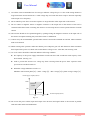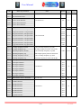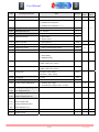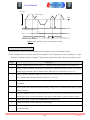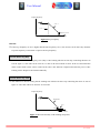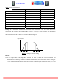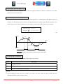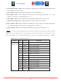
1
User's Manual User Manual CONTENTS 1. Safety Instructions………………………………………………………………………………… 2. Introduction………………………………………………………………………………………... 2.1 Inverter inspection 2.2 Product warranty 3. Installation and Wiring…………………………………………………………………………… 3.1 Operating Environment 3.2 Installation Method 3.3 Wiring Method 4. How to use keypad………………………………………………………………………………… 5. Inverter operation…………………………………………………………………………………. 5.1 Pre-operation inspection 5.2 Power on 5.3 Program mode 5.4 Keypad operation 5.5 External operation (Operation using external input signals) 6. Functions…………………………………………………………………………………………… 6.1 Function table 6.2 Description of functions A. Basic Functions B. Multi-steps Functions C. Terminal Functions D. Protective Functions E. Technical Functions 7. RS485 Modbus RTU Communication…………………………………………………………… 8. Encoder wiring…………………………………………………………………………………… 9. Maintenance and inspection……………………………………………………………………… 9.1 Precautions for maintenance and inspection 9.2 Daily inspection 9.3 Periodic inspection 10. Troubleshooting…………………………………………………………………………………. 11. Model and specifications………………………………………………………………………… 1/72 2 6 6 6 7 7 7 8 12 13 13 13 13 14 14 15 15 22 22 34 41 50 54 60 67 68 68 68 68 69 71 IH3-5.MOT User Manual SAFETY INSTRUCTIONS This instruction manual gives handling information and precautions for use of this inverter. Incorrect handling might cause an unexpected fault. Read this manual carefully before installing, connecting (wiring), operating, servicing, or inspecting the inverter. Familiarize yourself with all safety features before using this inverter. In this manual, safety messages are classified as follows: WARNING CAUTION Improper operation may result in serious personal injury or death. Improper operation may result in slight to medium personal injury or property damage. Note that the CAUTION level may lead to a serious consequence according to conditions. Please follow the instructions of both levels because they are important to personal safety. 1.1 Instructions on Use WARNING • This inverter is designed to drive a 3-phase induction motor and is not suitable for a single phase motor or others, as fire may result. • This inverter may not be used as a component of a life-support system or other medical device directly affecting the personal welfare of the user. • Safety equipment must be installed or the failure of this device may result in personal injury, property damage, or if there is a risk of accident. 1.2 Instructions on Installation • • • • • WARNING Mount this inverter on an incombustible material such as metal. Installing the inverter directly on or near a combustible or flammable material could lead to a fire. CAUTION Do not hold or carry this inverter by its cover, it may fall off. Do not drop the inverter, as injury may result. Ensure that the inverter and heat sink surfaces are kept free of foreign matter (lint, paper dust, small chips of wood or metal, and dust), as fire or accident may result. Do not install or operate a damaged inverter or an inverter with missing parts, as electric shock or injury may occur. 2/72 IH3-5.MOT User Manual 1.3 Instructions on Wiring • • • • • • • • • • WARNING Connect the inverter to power via a line-protection molded-case circuit breaker or fuse, as fire may result. Always connect a ground wire, as electric shock or fire may result. A licensed specialist must perform all wiring work, as electric shock may result. Turn off the power before wiring, as electric shock may result. Always install the inverter before wiring, as electric shock or injury may occur. CAUTION Confirm that the phases and rated voltage of this inverter match those of the AC power supply, as injury may result. Do not connect the AC power supply to the output terminals (U, V, W), as damage may result. Do not connect a resistor directly to the DC terminals (P, N), as fire may result. Do not fit capacitive equipment such as a power factor correction capacitor, noise filter or surge suppressor to the output of the inverter. The connection orientation of the output cables (U, V, W) to the motor will affect the direction of rotation of the motor. Ensure that the noise generated by the inverter, motor, or wiring does not adversely affect peripheral sensors and equipment, as accident may result. 1.4 Instructions on Operation • • • • • WARNING Be sure to install the front cover before turning on the power. Do not run the inverter with the front cover removed. Electric shock may occur. Do not operate switches with wet hands, as electric shock may result. The STOP key is valid only when the appropriate function setting has been made. Prepare an emergency stop switch separately. Make sure that the start signal is off before resetting the inverter alarm. A failure to do so may restart the motor suddenly. Do not touch inverter terminals when energized, even if the inverter has stopped. Electric shock may result. 3/72 IH3-5.MOT User Manual • • • • • CAUTION Do not start or stop the inverter using the main circuit power. Failure may result. Do not touch the heat sink or braking resistor because they become very hot. Burns may result. The inverter can be easily set for high-speed operation. Before changing its setting, examine the performance of the motor and machine. Injury may result The electronic over current protection does not guarantee protection of the motor from overheating. Before running an inverter which had been stored for a long period, always perform inspection and test operation. 1.5 Instructions on Maintenance, Inspection and Replacement WARNING • Wait a minimum of 5 minutes (30 HP or less) or 10 minutes (40 HP or more) after power has been turned off before starting inspection. Also confirm that the charge lamp is off and that DC voltage between terminals P and N does not exceed 25 V. Electrical shock may result. • Only authorized personal should perform maintenance, inspection, and replacement operation. Remove all metal jewelry such as watches and rings. Use insulated tools only. Electric shock or injury may result. CAUTION • Do not carry out a megger (insulation resistance) test on the control circuit of the inverter. 1.6 Instructions on Disposal CAUTION • Treat as industrial waste when disposing of inverter. 1.7 Other Instructions WARNNING • Never modify the product. Electric shock or injury may result. 4/72 IH3-5.MOT User Manual 1.8 Conformity to Low Voltage Directive in Europe CAUTION • The contact capacity of alarm output for any fault (NO, NC, CMR) is 5 A at 30 VDC, 5 A ≤ 250 VAC • The ground terminal should be connected to ground. Use a crimp terminal to connect a cable to the main circuit terminal or inverter ground terminal. • Use a single cable to connect the inverter ground terminal. Do not use more inverter ground terminals. • Where a residual-current protective device (RCD) is used for protection in case of direct or indirect contact, only a type B device is allowed on the supply side of this electrical equipment. Otherwise, another protective measure shall be applied such as separation of the electrical equipment from the environment by double or reinforced insulation or isolation of the electrical equipment and supply system by the transformer. • Use a molded-case circuit breaker (MCCB) and magnetic contactor (MC) that conform to EN or IEC standards. • Operate the inverter under over-voltage Category III conditions and maintain pollution Degree 2 or better as specified in IEC664. To maintain Pollution Degree 2 or better, install the inverter in a control panel structure (level NEMA 3 or higher) which is free from water, oil, carbon, dust etc. • For the input-output wiring of the drive, use cable diameter and type as specified in Appendix C in EN60204. • To ensure safety, install an optional AC reactor, DC reactor, or external braking resistor as follows: 1) Install inside an IP4X cabinet or barrier if electrical parts are exposed. 2) Install inside an IP2X cabinet or barrier if electrical parts are not exposed. • In case of external cooling system, cover the inverter rear side in order not to touch the main capacitor and braking resistor. 1.9 General Instructions • For clarity, some figures in this manual may show the inverter without covers for explanation purpose. Do not operate the device until all such covers have been replaced. The time required for the capacitors to discharge after the removal of power from the equipment. Capacitor discharge time: Min. 5 minutes 5/72 IH3-5.MOT User Manual INTRODUCTION Thank you for choosing this FRECON IH inverter. This inverter uses 32 bit CPU for multi-function in a variety of applications. 2.1 Inverter inspection Please inspect the following points after unpacking your inverter. If you have any problems or questions regarding the inverter, please contact A.P.Y. Engineering Co., Ltd. or the distributor you purchased the unit from. 1) Check the nameplate on the inverter cover to ensure that the specifications correspond to those you ordered. 2) Inspect visually if during shipping the unit have got any damage or disconnection on the parts or bent on cover on main unit panels. F 001 i - 4 H E DB FRECON Size of Inverter 1HP - 400HP DB: Built-in dynamic brake _: Option dynamic brake Built-in EMI Filter X iX Series H iH Series 2: Power Supply 1∅ 220V, 3∅ 220V 4: Power Supply 3∅ 380V IPM Version 2.2 Product warranty This product is guaranteed against defects in workmanship for 12 months from the purchasing date. However, the troubles caused by the following reasons are not covered by this warranty even in warranty period. 1) Problems caused by incorrect operation or by unauthorized repairs or modifications. 2) Problems resulting from using the inverter in the range outside the standard specification. 3) Damage to the inverter after purchase or during delivery. 4) Damage caused by earthquakes, fire, floods, lightning, abnormal voltage fluctuations or other natural disasters and secondary disasters. 6/72 IH3-5.MOT User Manual 5) 6) 7) 8) Damage caused by water. Damage caused by animal or insect. The external case or parts are damaged. Damage caused by intention, accident or carelessness INSTALLATION AND WIRING 3.1 Operating Environment Install this inverter in location that meets the conditions as follow. Item Specifications Location Indoors (a well-ventilated room) Ambient Temperature -10°C to +50°C (+14°F to +122°F) Relative Humidity 5 to 95 % (No condensation) Atmosphere The inverter must not be exposed to dust, direct sunlight, corrosive gas, explosive gas, inflammable gas, oil mist, vapor, or water. There must be minimum salt content in the atmosphere. Do not store where condensation may occur as a result of sudden changes in temperature Altitude 1000 m (3300 feet) or lower. After that derate by 3% for every extra 500 m up to 3000 m (88%) Vibration 3 mm peak from 2 to 9 Hz, 9.8 m/s2 from 9 to 20 Hz, 2m/s2 from 20-55 Hz, 1 m/s2 from 55 to 200 Hz. Note: The storage environment: same as details of the operating environment. 3.2 Installation Method • Install the inverter securely with screws or bolts in the vertical direction. Do not turn the inverter upside down or install in a horizontal position. Fig.3-1 • Since heat is generated during drive operation, the spaces shown in Fig.3-1 are required to ensure sufficient cooling. Do not install the inverter beneath a device sensitive to heat as heat radiates upward. • The heat sink may reach a temperature of 90°C (194°F) during inverter operation. Ensure that the material surrounding the product can withstand this temperature. 7/72 IH3-5.MOT User Manual • When installing this inverter in a control panel, consider ventilation to prevent the drive’s ambient temperature from exceeding the specified value. Do not install the product in an area from which heat can not be sufficiently released. • If two or more inverters must be installed in the same control panel, arrange the units horizontally to minimize the effect of heat. If two or more inverters must be installed vertically, place an insulated plate between the inverters to minimize the effect of heat. Clear area Air flow 10 cm (3.94”) Minimum FRECON INVERTER 5 cm (1.97”) 5 cm (1.97”) Minimum Minimum 10 cm (3.94”) Minimum Fig.3-1 3.3 Wiring Method 3.3.1 Wiring of the main circuit 1) Crimping terminals with insulation sleeves are recommended for use with the power and motor cables. 2) Cut the protective bushes of the wiring cover when running the cables. 3) Check that the power supply voltage is within the maximum allowable voltage marked on the nameplate of the inverter. Connect the AC power input terminals (R/L1(L), S/L2, T/L3(N)) to the power supply via a mold-case circuit breaker for circuit protection. 4) Check that the voltage, current and power of motor are within the maximum allowable capacity marked on the nameplate of the inverter. Connect the inverter output terminals (U/T1, V/T2, W/T3) to a 3-phase motor in correct phase sequence. 5) Power supply must not be applied to the output terminals (U/T1, V/T2, W/T3) of the inverter. Otherwise the inverter will be damaged. 6) After wiring, wire off-cuts must not be left in the inverter. Wire off-cuts can cause a fault, failure or malfunction. Always keep the inverter clean. When drilling mounting holes in a control box etc., exercise care to prevent chips and other foreign matter from entering the inverter. 8/72 IH3-5.MOT User Manual 7) Use cables of the recommended size for wiring to make the voltage drop 2 % or less. If the wiring distance is long between the inverter and motor, a cable voltage drop will cause the motor torque to decrease especially at the output of low frequency. 8) Do not install a power factor correction capacitor or surge absorber in the output side of the inverter. 9) Do not connect a magnetic starter or magnetic contactor to the output side of the inverter. If the load is connected while the inverter is running, the inverter over current protective circuit operates because of inrush current. 10) The inverter should not be operated/stopped by opening/closing the magnetic contactor at the input side of the inverter. Frequent switching may cause the inverter to malfunction. 11) Connect only the recommended optional brake resistor between the terminals B1 and B2. These terminals must not be shorted. 12) When rewiring after operation, make sure that the power lamp has gone off, and when more than 10 minutes have elapsed after power-off, check with a tester that the voltage is zero. After that, start rewiring work. 13) AC or DC reactor should be connected under the following condition. • The capacity of the power supply transformer exceeds 500 kVA and exceeds the rated capacity of the drive tenfold. (See Fig.3-2) • Used to prevent the inverter over voltage trip from occurring when the power factor capacitor in the power line is switched on and off. • When the voltage imbalance exceeds 3 % Imbalance rate between phase [%] = (Max. voltage [V] – Min. voltage [V])/3 phase average voltage [V] Power supply capacity (kVA) 4000 Reactor is needed 500 No reactor is needed 50 Fig.3-2 400 Inverter capacity (kVA) 14) Do not run the power cables (input and output of the inverter) and signal cables of the inverter in parallel with each other and do not bundle them. 9/72 IH3-5.MOT User Manual 15) If the cable from the inverter to the motor is very long, a high-frequency current may be generated by stray capacitance between the cables and result in an over current trip of the inverter, an increase in leakage current, or a reduction in current indication precision. 3.3.2 Grounding instructions 1) Leakage currents flow in the inverter. To prevent an electric shock, the inverter and motor must be grounded (220V class …class 3 grounding, grounding resistance 100Ω maximum), (380V class … special class 3 grounding, grounding resistance 10Ω or less). 2) Use the dedicated ground terminal to ground the inverter. (Do not use the screw in the case, chassis, etc.) 3) Ground the motor on the inverter side using one wire of the 4-core cable. 4) When using several inverter units side by side, ground the units as shown in (a) or (b) of Fig.3-3. Do not loop the ground wires as shown in (c). INV.1 INV.2 INV.3 INV.1 INV.2 INV.3 INV.1 INV.2 INV.3 (a) (b) (c) Fig. 3-3 3.3.3 Wiring of the control circuit 1) Separate control circuit wires from main circuit wires and other power cables to prevent erroneous operation caused by noise interference. 2) Use twisted shield or twisted-pair shielded wire for the control circuit line and connect the shielded sheath to the ground. 3) A wiring distance should be less than 20 m. 10/72 IH3-5.MOT User Manual 3.3.4 Wiring diagram Terminals Vs Vi Terminal R/L1 (L) S/L2 T/L3 (N) U/T1 V/T2 W/T3 P1 P2/B1 B2 P N Ci CM AD1 O1 O2 FWD REV CM I1 Description Connect to the commercial power supply Connect to a 3-phase induction motor Connect to DC reactor (P1) Connect to DC reactor (P2) or braking resistor (B1) Connect to braking resistor (B2) Connect to external braking unit (DC Bus + ) Connect to external braking unit (DC Bus - ) Connect the inverter chassis(case) to earth 11/72 I2 I3 I4 Terminal VS Vi, Ci I1, I2, …, I5 O1,O2 AD1 FWD REV +12 CM NO NC CMR I5 CM +12 NO CMR NC Description DC power supply 10V 15mA. Multi-function analog input terminals Multi-function digital input terminals Multi-function digital output terminals Multi-function analog output terminal Turn on to start forward rotation Turn on to start reverse rotation DC power supply 12V 100mA. Analog and Digital signals ground Fault contact normally open Fault contact normally close Fault contact common IH3-5.MOT User Manual HOW TO USE KEYPAD STATUS LED Show mode of the inverter FUNC KEY Press to select program mode and toggle to operation mode DISPLAY Show command value (frequency, torque, SP) or data in program mode STOP KEY Press to stop the inverter or reset fault SET KEY OPR mode: press to remember command value PRG mode: press to save data in a function UP/DOWN KEY OPR mode: press to increase or decrease command value PRG mode: press to increase or decrease data in a function RUN KEY OPR mode: press to run the inverter MOVE KEY OPR mode: press to select digit of command value to changing PRG mode: press to select digit of data to changing UNIT LED Show unit of display value ENTER KEY OPR mode: press to display motor current or PID feedback PRG mode: press to display data in a function 12/72 VOLUME OPR mode: adjust command value to increase or decrease IH3-5.MOT User Manual INVERTER OPERATION 5.1 Pre-operation inspection 1) 2) 3) 4) 5) 6) Check the following items before supplying power to the inverter. Check that the connections are correct. In particular, check that inverter terminals U, V and W are not connected to the power supply, and also check that the ground terminal is securely grounded. Check for short circuits and ground faults between the terminals and sections under power. Check for loose terminals, connectors, or screws. Check that the motor is disconnected from the mechanical equipment. Turn all switches off before turning on the power to make sure that the inverter does not start up or operate incorrectly when the power is turned on. Check the following after power-on: 6.1) No fault message is displayed on the keypad panel. 6.2) The fan inside the inverter is rotating. 5.2 Power On When the power is turn on, keypad shows “APY” and after that it shows the factory setting frequency (50.00 Hz). The inverter is in the stop mode. Note that the LED over the stop key is lit. 5.3 Program mode 1) Press FUNC key for entering the program mode. The display shows the function number “A-00”. If the display shows “PASS”, the program mode of inverter is locked. User can enter the program mode by press MOVE key, RUN key and SET key respectively. 2) Press UP or DOWN key to increase or decrease the basic function number. If user wants to enter the other program mode, press MOVE key one time. The character “A” is blink and then press UP or DOWN key to change it. (Fig. 5.1) 3) Press ENTER key to show the parameter in each function. 4) Press UP or DOWN key to change the parameter in the desire function. 5) Press SET key to save the parameter in memory. If user wants to change the parameter in the other function, please follow in 2)-5) again. 6) Press FUNC key to exit the program mode. 13/72 IH3-5.MOT User Manual Power on Operation mode Program mode RUN FUNC Yes MOVE Program Mode No Stop Inverter ENTER No Yes STOP SET Yes End Process Change Parameter No FUNC Fig. 5-1 5.4 Keypad operation 1) In stop mode, change the frequency to the desire value by pressing UP or DOWN key. 2) Press RUN key to start the inverter. The motor speed will be increased to the set frequency. The acceleration time corresponds to the parameter in A-10. The direction of rotation depends on the FWD/ REV terminals. 3) Press ENTER key to display the motor current and press ENTER key again to return the frequency display. 4) Press STOP key to stop the inverter. The motor speed will be decreased until stop. The deceleration time corresponds to the parameter in A-11. 5.5 External operation mode (Operation using external input signals) 1) Select external operation mode in A-03. (see in function details) 2) Close the terminal FWD-CM or REV-CM. (depend on the desire direction of rotation) 3) Select the external speed command in A-04. (see in function details) 14/72 IH3-5.MOT User Manual FUNCTION TABLE Code Basic Functions A-00 Monitor display selection A-01 A-02 A-03 A-04 A-05 A-06 A-07 A-08 A-09 A-10 A-11 A-12 A-13 A-14 A-15 Data 1. Frequency (Hz) 2. Revolution speed (rpm) 3. Machine speed Machine speed coefficient 0.01~200.00 multiply to frequency value Pole pair 1~8 (motor poles/2) Operation method 1. Start/Stop by keypad 2. Start/Stop by external pattern1 3. Start/Stop by external pattern2 4. 3-wire operation 5. RS485 operation (MODBUS-RTU) 6. Line/Inverter changeover operation Inverter command selection 1. Keypad command 2. External command from terminal Vi 3. External command from terminal Ci 4. External command from terminal Vi+Ci 5. External command from terminal Vi-Ci 6. UP/DOWN command 7. RS485 command (MODBUS-RTU) 8. Volume keypad command 9. Keypad command (Start at zero frequency) V/F pattern 1. Linear pattern 2. Square-law pattern Base voltage 80~240V. (220V. Series) 200~460V. (380V. Series) Base frequency 30.00~600.00 Hz Minimum frequency 0.00~Maximum frequency (Hz) Maximum frequency Minimum frequency~600.00 Hz 1st acceleration time 0.0~6000.0 sec 1st deceleration time 0.0~6000.0 sec Torque boost 0.0~20.0% of base voltage Maximum frequency for torque 0.0~100.0% of base frequency boost Slip compensation 0~200% of rated motor slip 0. Inactive Slip compensation during regenerative 1. Active 15/72 Control Default Control Mode Method 1 SPD ALL 1.00 2 1 ALL ALL ALL ALL 1 ALL ALL 1 SPD,PID V/F SPD,PID V/F ALL ALL SPD,PID ALL ALL ALL SPD,PID V/F SPD,PID V/F 220 380 50.00 0.00 120.00 5.0 5.0 3.0 10.0 0 0 IH3-5.MOT User Manual Code Basic Functions A-16 Starting method A-17 Start frequency A-18 A-19 A-20 A-21 Hold time at start frequency DC brake start duty DC brake start time Braking method A-22 Stop frequency A-23 A-24 A-25 A-26 DC brake stop duty DC brake stop time Switching frequency Factory setting Code B-00 B-01 B-02 B-03 B-04 B-05 B-06 B-07 B-08 B-09 B-10 B-11 B-12 B-13 B-14 B-15 Multi-step Functions 2nd acceleration time 2nd deceleration time 3rd acceleration time 3rd deceleration time 4th acceleration time 4th deceleration time 5th acceleration time 5th deceleration time 6th acceleration time 6th deceleration time 7th acceleration time 7th deceleration time 8th acceleration time 8th deceleration time Jog acceleration time Jog deceleration time Data 1. Start frequency 2. Start frequency after DC braking 3. Flying start (Search speed) 0.50~50.00 Hz (V/F & SSL) 0.00~50.00 Hz (VEC) 0.0~60.0 sec 1~100% of rated motor current 0.0~60.0 sec 1. Deceleration & stop 2. Deceleration & stop + DC braking 3. Free run stop (Coasting to stop) 0.50~50.00 Hz (V/F & SSL) 0.00~50.00 Hz (VEC) 1~100% of rated motor current 0.0~60.0 sec 1~15 kHz 0. Inactive 1. Active 2. Program locked Data 0.0~6000.0 sec 16/72 Control Default Control Mode Method 1 SPD,PID ALL 0.50 0.0 30 0.0 1 0.50 30 0.0 3 0 SPD,PID ALL SPD,PID V/F,SSL SPD,PID ALL SPD,PID ALL SPD,PID ALL SPD,PID V/F,SSL SPD,PID ALL ALL ALL ALL ALL Control Default Control Mode Method 5.0 ALL IH3-5.MOT ALL User Manual Code B-16 B-17 B-18 B-19 B-20 B-21 B-22 B-23 B-24 B-25 B-26 B-27 B-28 B-29 B-30 B-31 B-32 B-33 B-34 B-35 B-36 B-37 B-38 B-39 B-40 B-41 B-42 B-43 B-44 B-45 B-46 B-47 B-48 B-49 B-50 B-51 B-52 B-53 Multi-step Functions Soft acceleration time Soft deceleration time S-curve accel start time S-curve accel end time S-curve decel start time S-curve decel end time 1st speed limit 2nd speed reference/ 2nd speed limit 3rd speed reference / 3rd speed limit 4th speed reference / 4th speed limit 5th speed reference / 5th speed limit 6th speed reference / 6th speed limit 7th speed reference / 7th speed limit 8th speed reference / 8th speed limit Jog speed reference/ Jog speed limit 1st Jump frequency bottom 1st Jump frequency top 2nd Jump frequency bottom 2nd Jump frequency top 3rd Jump frequency bottom 3rd Jump frequency top 2nd torque reference 3rd torque reference 4th torque reference 5th torque reference 6th torque reference 7th torque reference 8th torque reference Jog torque reference PID reference accel / decel time 2nd PID reference 3rd PID reference 4th PID reference 5th PID reference 6th PID reference 7th PID reference 8th PID reference Jog PID reference Data 0.0~6000.0 sec Control Default Control Mode Method 10.0 0.0~6000.0 sec 0.0 0.00~600.00 Hz 10.00 20.00 30.00 40.00 50.00 60.00 70.00 80.00 5.00 0.00 0.00~1st Jump frequency top (Hz) 1st Jump frequency bottom~600.00 Hz 0.00~2nd Jump frequency top (Hz) 2nd Jump frequency bottom~600.00 Hz 0.00~3rd Jump frequency top (Hz) 3rd Jump frequency bottom~600.00 Hz 0.0~200.0% 0.0~60.0 sec 0.0~100.0% 17/72 20.0 30.0 40.0 50.0 60.0 70.0 80.0 10.0 0.0 20.0 30.0 40.0 50.0 60.0 70.0 80.0 10.0 ALL ALL TRQ VEC,SSL SPD,TRQ ALL SPD,PID ALL TRQ VEC,SSL PID ALL PID ALL IH3-5.MOT User Manual Code C-00 C-01 C-02 C-03 C-04 Terminal Functions Digital input terminal1 (I1) Digital input terminal2 (I2) Digital input terminal3 (I3) Digital input terminal4 (I4) Digital input terminal5 (I5) C-05 Digital output terminal1 (O1) C-06 Digital output terminal2 (O2) C-07 C-08 C-09 C-10 C-11 C-12 SST2 in DC brake start SST2 in DC brake stop FAR hysteresis FDT level FDT hysteresis Analog input terminal Vi C-13 Bias setting for Terminal Vi C-14 Direction of bias Terminal Vi C-15 Gain setting of Terminal Vi Can’t change during operation Can change during operation Data 1. Multi-step frequency1 (X1) 2. Multi-step frequency2 (X2) 3. Multi-step frequency3 (X3) 4. Jog frequency (JOG) 5. External reset (RST) 6. Reset hold (RH) 7. Up command (UP) 8. Down command (DOWN) 9. ACC / DEC selection (SOFT) 10. Free run (FR) 11. External fault (THR) 12. Line / Inverter changeover selection (CS) 1. Start / Stop signal (SST1) 2. Start / Stop signal with DC brake (SST2) 3. Frequency agree signal (FAR) 4. Frequency level detection signal (FDT) 5. Overload warning signal (OLW) 6. Inverter magnetic contactor signal (MCI) 7. Line magnetic contactor signal (MCL) 0~100% 0.00~10.00 Hz 0.00~600.00 Hz 0.00~30.00 Hz 1. 0-10 V. 2. -10 to 10 V. (Option card) 3. 4-20 mA. (Modify board) 0.0~Gain setting of Terminal Vi (at 0V. or 4 mA.) 1. Positive 2. Negative Bias setting of Terminal Vi ~600.00 Hz (at 10V. or 20mA.) Control mode 1. SPD = Speed mode (E-00 = 1, 2) 2. PID = PID build-in mode (E-00 = 3, 4) 3. TRQ = Torque mode (E-00 = 5, 6) 4. ALL = SPD, PID and TRQ 18/72 Control Default Control Mode Method 1 ALL ALL 2 3 4 5 1 3 50 0.00 50.00 0.00 1 0.0 1 ALL ALL SPD,PID ALL SPD ALL ALL ALL 100.0 Control method 1. V/F = V/F control (E-01 = 1) 2. VEC = Vector control (E-01 = 2) 3. SSL = Sensorless control (E-01 = 3) 4. ALL = V/F, VEC and SSL IH3-5.MOT User Manual Code Terminal Functions C-16 Analog input Terminal Ci C-17 Bias setting for Terminal Ci C-18 Direction of bias Terminal Ci C-19 Gain setting of Terminal Ci C-20 Analog input filter C-21 Analog output terminal AD1 C-22 Analog output signal AD1 C-23 Adjust analog output signal C-24 Station address C-25 Communication speed C-26 Data format C-27 Reply interval C-28 Communication loss time out C-29 Time out action C-30 Digital ratio multiplier C-31 Digital ratio divisor Control Data Default Control Mode Method 1. 0-10 V. (Modify board) 3 2. -10 to 10 V. (Option card) 3. 4-20 mA. 0.0~Gain setting of Terminal Ci (at 0V. or 4mA.) 0.0 ALL ALL 1. Positive 1 2. Negative Bias setting of Terminal Ci ~600.00 Hz 100.0 (at 10V. or 20mA.) 0.00~3.00 sec 0.10 1. 0-10V 1 2. 4-20mA (Modify board) 1. Show inverter set point 2 2. Show inverter set point run 3. Show motor current 4. Show motor voltage ALL ALL 5. Show motor speed 6. Show motor torque 7. Show motor power 8. Show DC bus voltage 9. Show PID feedback 0~200% of duty 100 0 (Master mode), 1~247 (Slave mode) 1 1. 2400 bits/sec 3 2. 4800 bits/sec 3. 9600 bits/sec 4. 19200 bits/sec 1. 8-N-1 (No parity & 1 stop bit) 1 2. 8-N-2 (No parity & 2 stop bit) 3. 8-E-1 (Even parity & 1 stop bit) ALL ALL 4. 8-O-1 (Odd parity & 1 stop bit) 0.00~1.00 sec. 0.01 0.0~60.0 sec. 0.0 0. Continuous operation 0 1. Decel to stop (up to A-21) 2. Fault and Coasting to stop 1~9999 100 19/72 IH3-5.MOT User Manual Code Protective Functions D-00 Electronic thermal overload D-01 Electronic thermal overload level D-02 Stall prevention D-03 Stall prevention current level D-04 Stall prevention voltage level D-05 Auto restart method D-06 Restart time D-07 History fault D-08 D-09 D-10 D-11 Line MC interlock time Inverter MC interlock time Advanced phase output voltage Motor wiring protection Data 0. Inactive 1. Flat rate 2. Derate 20~105% of rated inverter current 0. Inactive 1. Stall prevention current 2. Stall prevention voltage 3. Stall prevention current + voltage 50~200% of rated inverter current 80~100% of maximum voltage 0. Inactive 1. Start frequency 2. Start frequency after DC braking 3. Flying start (Search speed) 0.0~60.0 sec [1] [2] [3 ] [4] [1] = The last history fault [2] = The third history fault [3] = The second history fault [4] = The first history fault 0.00~60.00 sec. 0.00~60.00 sec. 0~360 degree 0. Not check motor wiring 1. Check motor wiring Code Technique Functions E-00 Control mode Data 1. Speed mode 2. Speed mode + Energy save* 3. PID + Speed mode 4. PID + Speed mode + Energy save* 5. Torque mode 4 quadrant 6. Torque mode 3 quadrant E-01 Control method 1. V/F (Open loop) 2. Vector (With speed sensor) 3. Senserless (Without speed sensor) E-02 Speed loop proportional gain (Kp) 1~9999 E-03 Speed loop integral time (Ti) 20/72 Control Default Control Mode Method 1 ALL ALL 80 3 150 90 0 0 0000 0.10 3.00 0 0 SPD,PID ALL SPD,PID V/F SPD,PID ALL SPD,PID ALL ALL ALL SPD V/F ALL ALL Control Default Control Mode Method 1 ALL ALL 1 ALL ALL 500 ALL VEC,SSL IH3-5.MOT User Manual Code Technique Functions E-04 Torque limiter E-05 PID controller feedback E-06 E-07 E-08 E-09 PID proportional band (PB) PID integral time (Ti) PID differential time (Td) PID action selection E-10 E-11 E-12 E-13 E-14 Pulses of encoder Rated motor speed Magnetizing current Rated motor current Autotune parameters E-15 Size of inverter E-16 Size of motor E-17 Voltage gain E-18 Current gain E-19 Deadtime compensation E-20 DC bus voltage compensation E-21 E-22 E-23 E-24 E-25 E-26 E-27 E28 E-29 E-30 CCL proportional gain (Kp) CCL integral time (Ti) Adaptive gain (Kp) Adaptive integral time (Ti) Stator resistance (Rs) Rotor resistance (Rr) Leakage inductance (σLs) Stator inductance (Ls) Torque filter / Current filter Inverter version Data 0~200% of rated motor torque 1. Feedback from terminal Vi 2. Feedback from terminal Ci 3. Feedback from terminal Vi + Ci 0.1~1000.0% 0.0~600.0 sec. 0.00~60.00 sec. 1. Direct action 2. Reverse action 1~9999 pulses/rev 1~9999 rpm 1~100% of rated inverter current 1~200% of rate inverter current 0. Inactive 1. Rotate tuning 2. Standstill tuning P01~P400 (380V. Series) 0.5HP~75HP (220V. Series) P01~P400 (380V. Series) 0.5HP~75HP (220V. Series) 80~240V. (220V. Series) 200~460V. (380V. Series) 1~9999 0~100% of 6.25 usec 1. Used DC bus voltage 2. Fixed DC bus voltage at 310V. or 540V. 1~9999 Control Default Control Mode Method 100 ALL VEC,SSL 2 100.0 1.0 0.00 2 PID ALL ALL VEC ALL ALL ALL VEC,SSL ALL ALL factory ALL ALL size size 1 SPD,PID V/F 500 ALL VEC,SSL 1~9999 500 ALL SSL 1~9999 size ALL VEC,SSL 1~256 - 128 - ALL ALL - - 21/72 1024 1420 size size 0 size size IH3-5.MOT User Manual BASIC FUNCTIONS A-00 Monitor Display Selection This function is used for setting the displayed value on keypad which is used as the command value in the speed-control mode (SPD). Data 1 2 3 Description The frequency is displayed and can be set from 0.00 ~ 600.00 Hz (LED lit at Hz position). The motor speed (LED lit at M/S position) is displayed. The displayed value depends on the data in function A-02 as following equation: Speed = 60 * frequency / pole pair (A-02) ….(1) The machine speed (LED lit at M/S position) is displayed. The displayed value depends on the data in function A-01 as following equation: Machine speed = coefficient(A-01) * frequency ….(2) Remark: In the torque-control mode (TRQ). The keypad displays the torque command value in percentage that up to the size of motor. In the PID-controller mode. The keypad displays the command value of the PID controller in percentage that up to the rated value of the sensor. A-01 Machine Speed Coefficient The coefficient in this function is used as the multiplier in the equation (2). The value can be set from 0.01~200.0 Example If we want to display the machine speed as 5.0 m/s when the motor is running at 50 Hz, we must use the coefficient value equals 0.1 A-02 Pole Pair This function is used for setting the pole pair of motor which equal to the number of motor’s pole divided by 2 The value can be set from 1~8. Example The 4-poles motor has 2 pole pairs. 22/72 IH3-5.MOT User Manual A-03 Operation Method This function is used for setting the start and stop method of the inverter in every control mode. Data 1 2 3 4 5 6 Description Control the operation via the RUN/STOP button on the keypad and set the spin direction via the CM-FWD or CM-REV connection as shown in figure 1. External Command (Format 1): Control the operation and the spin direction via the CM-FWD or CM-REV connection by using switch or relay contact as shown in figure 2. External Command (Format 2): Control the operation via the CM-FWD connection and set the spin direction via the CM-REV connection as shown in figure 3. 3-wire operation control: Control the operation via the CM-RH connection and set the spin direction via the FWD or REV connection as shown in figure 4 and 5. Control the operation via the RS485 MODBUS RTU communication. External Command for Line change-over mode: Use the 3-wire operation control scheme in addition with the using of the CS connection as the Line-Inverter transfer selector and the MCI, MCL connection as the Magnetic contactor controller (optional card). The wiring diagram is shown in figure 26 and the operation is also shown in figure 27. Direction Output frequency Time Forward signal (FWD+CM) Reverse signal (REV+CM) Press RUN key Press STOP key Figure 1 The sequence of operation control by keypad 23/72 IH3-5.MOT User Manual Direction Output frequency Time Forward signal (FWD+CM) Reverse signal (REV+CM) Figure 2 The sequence of the external operation control in format 1 Direction Output frequency Time Forward signal (FWD+CM) Reverse signal (REV+CM) Figure 3 The sequence of the external operation control in format 2 FWD REV RH CM Figure 4 Connection for the 3-wire operation control 24/72 IH3-5.MOT User Manual Direction Output frequency Time Forward signal (FWD+CM) Rerverse signal (REV+CM) Reset Hold signal (RH+CM) Figure 5 The sequence of the 3-wire operation control A-04 Inverter Command Selection This function is used for inverter command selection (Digital, Analog or UP/DOWN control). The command value will be used as the speed command (1st speed reference), the torque command (1st torque reference) or the PID controller command (1st PID reference) depending on the control mode (function E-00). Data 1 2 3 4 5 6 7 8 9 Description Digital Command: Adjust the set point via ∧/∨ button on the keypad with the 0.01 Hz resolution. Analog Voltage Command: Adjust the set point by the 1~5kΩ potentiometer or the 0~10V external input voltage connected to the Vi terminal. More details can be set in function C-12 to C-15. Analog Current Command: Adjust the set point by the 4~20mA current source/sensor connected to the Ci terminal. More details can be set in function C-16 to C-19. The set point is the summation of the analog voltage at the Vi terminal and the analog current at the Ci terminal. The set point is the difference between the analog voltage at the Vi terminal and the analog current at the Ci terminal. External Command: Increase or decrease the set point via the CM-UP and CM-DOWN connection respectively. Figure 6 shows the example when using with the format 1 external operation control. Adjust the set point via the RS485 MODBUS RTU communication Adjust the set point via the volume knob on the keypad. Start running from zero set point and can adjust the set point via ∧/∨ button on the keypad with the 0.01 Hz resolution. 25/72 IH3-5.MOT User Manual Direction Output frequency Time Forward signal (FWD+CM) Reverse signal (REV+CM) Up signal (UP+CM) Down signal (DOWN+CM) Figure 6 The sequence of operation when receiving the set point command from UP/DOWN A-05 V/F Pattern This function is used for the voltage/frequency pattern selection when using the V/F control mode. Data 1 2 Description Linear pattern: The pattern relation between the voltage and frequency is linear. Using for constant load torque, such as Conveyor etc. (see Figure 7) Square pattern: The pattern relation between the voltage and frequency is square function. Normally using with the Fan or Pump load. (see Figure 7) Output voltage Base voltage (A-06) A-05 = 1 A-05 = 2 Base frequency (A-07) Output frequency Figure 7 The pattern of output voltage and frequency 26/72 IH3-5.MOT User Manual A-06 Base Voltage This function is specified by the rated voltage of motor for using in the V/F control mode (see Figure 7). The value can be set from 80V to 240V for 220V inverter model and 200V to 460V for 380V inverter model. Remark: The maximum output voltage of inverter cannot be over the input voltage of inverter. A-07 Base Frequency This function is specified by the rated frequency of motor. The value in this function is used for partitioning between the constant torque and the constant power (field weakening) range as seen in figure7. The value can be set from 30.0Hz to 600.00Hz. A-08 Minimum Frequency This function is used as the minimum limit of the output frequency to protect the motor from operating at improper frequency (see Figure 8). The value can be set from 0.00Hz to the maximum frequency (A-09). A-09 Maximum Frequency This function is used as the maximum limit of the output frequency to protect the motor from operating at improper frequency (see Figure 8). The value can be set from the minimum frequency (A-08) to 600.00Hz. Output frequency Maximum freq (A-09) Minimum freq (A-08) Setting frequency Figure 8 Maximum and minimum limit of the output frequency 27/72 IH3-5.MOT User Manual A-10 1st Acceleration Time A-11 1st Deceleration Time These functions are used for setting the linear acceleration and deceleration time of motor for the first speed command (1st speed reference). The values can be set from 0.0 to 6000.0 second. The time values in the function A-10 and A-11 are used as the linear middle-time for the S-curve operation together with the start and end time in the function B-18~ B-21 based on 50 Hz, which mean that if we set A10 and A-11 to be 5 and B-18~B-21 to be 0, the motor will accelerate from 0.00 Hz to 50.00 Hz in 5 second and also decelerate from 50.00 Hz to 0.00 Hz in 5 second. Example If we want the linear acceleration and deceleration time of motor between 0.00Hz~100.0Hz to be 5 second, we must set the function A-10 and A-11 to be 2.5 and B-18~B-21 to be 0 (see Figure9). Output frequency 100 Hz 50 Hz Time A-10=2.5 5 sec 5 sec A-11=2.5 Figure9 Setting acceleration and deceleration speed time is linear Remark: In the torque-control mode (TRQ), this function is used for setting the linear acceleration and deceleration time of the torque value for the fist torque command (1st torque reference). In the PID controller mode, this function is used for setting the linear acceleration and deceleration time of the frequency value for the of PID controller command (1st PID reference). A-12 Torque Boost This function is used for setting the starting output voltage for increasing the torque of motor at the low frequency operation in the V/F control mode (see Figure 10, 11). The value can be set from 0.0 to 20.0% of base voltage (A-06). 28/72 IH3-5.MOT User Manual A-13 Maximum Frequency for Torque Boost This function is the maximum frequency for increasing the output voltage in the V/F control mode (see Figure 10, 11). The value can be set from 0.0 to 100.0% of base frequency (A-07). Output voltage A-06 A-12 A-07 Output frequency A-13 Figure 10 Example of the torque boosting in V/F control (linear pattern) Output voltage A-06 A-12 A-07 Output frequency A-13 Figure 11 Example of the torque boosting in V/F control (square pattern) A-14 Slip Compensation This function is used to compensate the decreasing speed that caused from load in the V/F control mode. The value can be set from 0~200% of the rated slip. The compensation result can be shown as in figure 12. For the correct slip compensation, user must set the correct data in following functions: ¾ Rated speed of motor in function E-11 ¾ No load current in function E-12 ¾ Rated current of motor in function E-13 29/72 IH3-5.MOT User Manual A–15 Slip Compensation during Regenerative Data 0 1 Description No slip compensation in the regenerative region. Do slip compensation in the motor and regenerative region. Torque No comp 100% comp 200% comp Motoring Speed 200% comp Regenerative 100% comp No comp Figure 12 Slip compensation in the motoring and regenerative region A-16 Starting Method This function is used for the motor starting method selection before the speed is accelerated to the set point. Data 1 2 3 Description Start from the starting frequency. (More details in function A-17 and A-18) Start from the starting frequency after the DC braking. This setting can decrease the starting current because the motor is slow down or stop already. (More details in function A-19 and A-20) Start by the search speed technique. This method is good for starting the motor that is still spinning because the inverter will try to apply the matched frequency that making low slip leading to the low starting current as seen in figure 13. 30/72 IH3-5.MOT User Manual Output frequency Base frequency Set point frequency Motor speed Acceleration Time Search speed Figure 13 The speed searching in V/F and sensorless control mode Remark: In the V/F and sensorless (SSL) control mode, the search-speed technique should be applied only when the speed of motor below the base frequency (A-06). A-17 Start Frequency This function is used for setting the starting frequency of motor as seen in figure 14. The value can be set from 0.00~50.00 Hz in the Vector control mode (VEC) or 0.50~50.00 Hz in the V/F and sensorless (SSL) control mode. Remark: The inverter can be started only when the set point frequency is more than or equal to the start frequency. A-18 Hold Time at Start Frequency This function is used for setting the start frequency holding time as seen in figure 14. The value can be set from 0.0~60.0 second. Output frequency Set point frequency Start freq (A-17) Acceleration Time Hold time (A-18) Figure 14 The start frequency and its holding time 31/72 IH3-5.MOT User Manual A-19 DC Brake Start Duty This function is used for setting the power (duty) of DC braking before start running the motor as seen in figure 15. The value can be set from 1~100% of the rated current of motor in the V/F and sensorless (SSL) control mode. In the Vector control mode (VEC), this function is neglected because the power of DC braking will be adapted to the load automatically. A-20 DC Brake Start Time This function is used for setting the DC braking time before start running the motor as seen in figure 15. The value can be set from 0.0~60.0 second. Output frequency Set point frequency A-19 Acceleration A-17 Time A-20 Figure 15 The time and duty of DC braking (Starting time) A-21 Braking Method This function is used to select the braking method Data 1 2 3 Description Decrease speed until reaching the stop frequency (A-22) and then stop. Decrease speed until reaching the stop frequency (A-22) and then stop the motor by DC braking. (More details in function A-23 and A-24) Stop control immediately and let the motor free running as shown in figure 16 A-22 Stop Frequency This function is used for setting the stop frequency as shown in figure 16. The value can be set from 0.00 ~ 50.00 Hz in the vector control mode (VEC) or 0.50 - 50.00 Hz in the V/F and sensorless control (SSL) mode. 32/72 IH3-5.MOT User Manual Output frequency A-21 = 1 A-21 = 3 Stop freq (A-22) Time Figure16 Stop frequency Remark: If the stop frequency (A-22) is higher than the start frequency (A-17), the inverter can be start only when the set point frequency is more than or equal to the stop frequency. A-23 DC Brake Stop Duty This function is used for setting the power (duty) of DC braking after the inverter stop controlling the motor as seen in figure 17. The value can be set from 1~100% of the rated current of motor in the V/F and sensorless (SSL) control mode. In the Vector control mode (VEC), this function is neglected because the power of DC braking will be adapted to the load automatically. A-24 DC Brake Stop Time This function is used for setting the DC braking time after the inverter stop controlling the motor as seen in figure 17. The value can be set from 0.0~60.0 second. Output frequency Deceleration A-23 A-22 A-24 Time Figure 17 The time and duty of DC braking (Stop time) 33/72 IH3-5.MOT User Manual A-25 Switching Frequency This function is used for setting the switching frequency of inverter from 1~15 kHz. Remark: Increasing the switching frequency leads to lower noise, however it will be more switching loss and leakage current. A-26 Factory Setting Data 0 1 2 Description Use the changed value/Unlock function. Use the factory setting from A – 00 to E –14 Lock function MULT-STEP FUNCTIONS B-00 2nd Acceleration Time B-01 2nd Deceleration Time B-02 3rd Acceleration Time B-03 3rd Deceleration Time B-04 4th Acceleration Time B-05 4th Deceleration Time B-06 5th Acceleration Time B-07 5th Deceleration Time B-08 6th Acceleration Time B-09 6th Deceleration Time B-10 7th Acceleration Time B-11 7th Deceleration Time B-12 8th Acceleration Time B-13 8th Deceleration Time B-14 Jog Acceleration Time B-15 Jog Deceleration Time In the speed control and PID control mode, the function B–00 to B-15 are used for setting the linear acceleration and deceleration times of the 2nd–8th speed commands and the jog speed command in the function B–23 to B–30 as seen in figure 18. The value can be set from 0.0 ~ 600.0 second. In the torque-control mode (TRQ), these functions are used for setting the linear acceleration and deceleration times for the 2nd–8th torque commands and also the 9th torque command (Jog) in function B-37 to B-44. 34/72 IH3-5.MOT User Manual Output frequency Speed1 Decel JOG Speed2 Accel1 Decel2 Speed JOG Accel2 JOG+CM FWD+CM Time X1+CM Figure 18 Acceleration and deceleration time for Multi–speed operation B-16 Soft Acceleration Time B-17 Soft Deceleration Time In the speed control and PID control mode, the function B–16 and B-15 are used for setting the soft acceleration and deceleration time of every speed commands for the soft operation that can be activated by the CM-SOFT connection as seen in figure 19. The value can be set from 0.0~6000.0 second. In the torque-control mode (TRQ), these functions are used for setting the soft acceleration and deceleration time of every torque commands for the soft operation. Output frequency B-16 Set point frequency B-17 A-11 A-10 Time Press Stop key Press RUN key SOFT signal Figure 19 Soft acceleration and deceleration 35/72 IH3-5.MOT User Manual B-18 S-Curve Acceleration Start Time B-19 S-Curve Acceleration End Time B-20 S-Curve Deceleration Start Time B-21 S-Curve Deceleration End Time These functions are used for setting the S-curve acceleration and deceleration time from 0.0~6000.0 second. These functions are used together with the linear acceleration and deceleration time in the function A-10, A11 and B-00 to B-17. The time values in these functions are based on 50 Hz which mean that if we set the function B-18 to B-21 to be 5, the motor will be accelerated from 0.00 Hz to 50.00 Hz and decelerated from 50.00 Hz to 0.00 Hz with the 5 second of start and end time interval of s-curve each. Because of the 3-part mixing of the acceleration and deceleration time, user can change the pattern of the acceleration and deceleration in 8 styles as seen in figure 20. The setting for all patterns are shown in table 1 Output frequency 1 3 4 2 Time Output frequency 5 6 7 8 Time Figure 20 8 patterns of s-curve acceleration and deceleration 36/72 IH3-5.MOT User Manual Table 1 s-curve setting method S-Curve Start Time 1 X 2 X 3 O 4 X 5 O 6 O 7 X 8 O Linear ACC&DEC Time X O X X X O O O S-Cure End Time X X X O O X O O Example If we set the linear acceleration and deceleration time in function A-10 and A-11 equal to the s-curve acceleration and deceleration time in function B-18 to B-21 at 5 second, the total acceleration and deceleration time between 0.00 Hz and 50.00 Hz are 15 second as shown in figure 21. Output frequency 50 Hz B-18 A-10 B-19 B-20 A-11 B-21 5 sec 5 sec 5 sec 5 sec 5 sec 5 sec Time Figure 21 Example of s-curve setting Remark: In the torque-control mode (TRQ), these functions are used for setting the s-curve acceleration and deceleration time of the torque command. In the PID controller mode, these functions are used for setting the s-curve acceleration and deceleration time of the frequency command together with function A-10, A-11 and B-00 to B-17. 37/72 IH3-5.MOT User Manual B-22 1st Speed Limit: TRQ B-23 2nd Speed References: SPD / 2nd Speed Limit: TRQ B-24 3rd Speed References: SPD / 3rd Speed Limit: TRQ B-25 4th Speed References: SPD / 4th Speed Limit: TRQ B-26 5th Speed References: SPD / 5th Speed Limit: TRQ B-27 6th Speed References: SPD / 6th Speed Limit: TRQ B-28 7th Speed References: SPD / 7th Speed Limit: TRQ B-29 8th Speed References: SPD / 8th Speed Limit: TRQ B-30 Jog Speed References: SPD/ 9th Speed Limit: TRQ In the speed-control mode, function B-23 to B-30 are used for setting the 2nd-8th speed references and jog speed that can be activated by the connection of X1, X2, X3 or JOG with CM terminal as shown in table 2 and figure 22. The value can be set from 0.00 Hz to 600.0 Hz. In the torque-control mode (TRQ), these functions are used for setting the speed limit of the 2nd-8th torque commands and also the 9th torque command (jog command) in function B-37 to B-44. Table 2 The relation between the command and the X1, X2, X3 and JOG terminal state X1 X2 X3 Command 1st OFF OFF OFF Command 2nd ON OFF OFF Command 3 rd OFF ON OFF Command 4 th ON ON OFF Command 5 th OFF OFF ON Command 6 th ON OFF ON th Command 7 OFF ON ON Command 8 th ON ON ON Command JOG ON/OFF ON/OFF ON/OFF Remark: The JOG command has first priority as seen in table 2. 38/72 JOG OFF OFF OFF OFF OFF OFF OFF OFF ON IH3-5.MOT User Manual FWD Speed1 B-23 B-24 B-25 B-26 B-27 B-28 B-29 Output frequency B-30 Time FWD signal X1 signal X2 signal X3 signal JOG signal Figure 22 The sequence of multi-speed operation when use the X1, X2, X3 and JOG terminal B-31 1st Jump Frequency Bottom B-32 1st Jump Frequency Top B-33 2nd Jump Frequency Bottom B-34 2nd Jump Frequency Top B-35 3rd Jump Frequency Bottom B-36 3rd Jump Frequency Top These functions are used for setting the frequency ranges that we don’t want the motor to be operated (jump frequency) for avoiding of the mechanical vibration as seen in figure 23 The bottom frequency can be set from 0.00 Hz to the top frequency and the top frequency can be set from the bottom frequency to 600.0 Hz. Output frequency B-35 B-33 B-31 B-32 B-34 B-36 Setting frequency Figure 23 Jump frequency operations 39/72 IH3-5.MOT User Manual B-37 2nd Torque Reference B-38 3rd Torque Reference B-39 4th Torque Reference B-40 5th Torque Reference B-41 6th Torque Reference B-42 7th Torque Reference B-43 8th Torque Reference B-44 Jog Torque Reference These functions are used in the torque-control mode only. The value in function B-37 to B-44 are used as the 2nd-8th torque commands and the 9th torque command (jog command) that can be activated by the connection of X1, X2, X3 or JOG with CM terminal as shown in table 2. The value can be set from 0.0~200.0% of the rated torque of motor. B-45 PID Reference Acceleration / Deceleration Time This function is used in the PID controller mode only. The value in this function is used as the acceleration and deceleration time for the 1st-9th set points. The value can be set from 0.0-60.0 second. B-46 2nd PID Reference B-47 3vc PID Reference B-48 4th PID Reference B-49 5th PID Reference B-50 6th PID Reference B-51 7th PID Reference B-52 8th PID Reference B-53 Jog PID Reference This function is used for setting 2nd-8th set points and also the 9th (jog command) set point as seen in figure 24 that can be activated by the connection of X1, X2, X3 or JOG with CM terminal as shown in table 2. The value can be set from 0.0~100.0% of the rated of sensor. PID signal Set point2 Accel/Decel (B-45) Set point1 Set point3 Process value Time X1+CM FWD+CM X2+CM Figure 24 Example of multi-PID set point operation 40/72 IH3-5.MOT User Manual TERMINAL FUNCTIONS C-00 Digital Input Terminal I1 C-01 Digital Input Terminal I2 C-02 Digital Input Terminal I3 C-03 Digital Input Terminal I4 C-04 Digital Input Terminal I5 These functions are used for setting type of the digital input terminals (I1-I5), which can be set as the following table. The setting of each input can’t be duplicated. Data 1 2 3 4 5 6 7 8 9 10 11 12 Description Multi–step frequency 1 (X1) Multi–step frequency 2 (X2) Multi–step frequency 3 (X3) Jog frequency (JOG) selection External reset (RST) Reset hold (RH) for 3 wire operation UP command (UP-Down control method) Down command (UP-Down control method) Soft ACC / DEC selection Free run (FR) External fault (THR) CS for Line change-over operation C-05 Digital Output Terminal O1 C-06 Digital Output Terminal O2 These functions are used for setting type of the O1 and O2 output terminal. 41/72 IH3-5.MOT User Manual Data 1 2 3 4 5 6 7 Description Start / stop signal (SST1) Out the signal while the motor is running. Start / stop signal with DC brake (SST2) Out the signal while the motor is running including DC braking. (more details in function C-07, C08) Frequency agreement signal (FAR) Out the signal when the output frequency equals to the set point frequency. (more details in function C-09) Frequency level detection signal (FDT) Out the signal when the output frequency is more than or equal to the specified frequency. (more details in function C-10, C-11) Over load warning signal (OLW) Out the signal when load of motor is more than the detection level set in D-01 and stop out the signal when collective load of motor is less than the detection level as seen figure 25. Inverter magnetic contactor signal (MCI) Out the signal when the inverter starts until ready to transfer the motor to the line or when the inverter controls the motor again with the delay time in function D-09 as shown in figure 27 Line magnetic contactor signal (MCL) Out the signal when the inverter transfer the motor to the line with the delay time in function D-08 and stop the signal when the inverter controls the motor again as shown in figure 27 Output current D-01 motor temperature up temperature down Time OWL signal Figure 25 Over load warning signal 42/72 IH3-5.MOT User Manual Figure 26 Wiring diagram for the Line change-over operation Direction Output frequency Search speed Time MCI MCL D-08 D-09 RH FWD CS Figure 27 The sequence of the Line change-over operation C-07 Start Stop Signal (SST2) in DC Brake Start This function is used for setting the time delay of SST2 signal when DC brake is activated at the start of running as seen in figure 28. The value can be set from 0~100% of the DC brake start time in function A-20. 43/72 IH3-5.MOT User Manual C-08 Start Stop Signal (SST2) in DC Brake Stop This function is used for setting the time delay of SST2 signal when DC brake is activated at the end of running as seen in figure 28. The value can be set from 0~100% of the DC brake stop time in function A-24. Output frequency Set point1 C-07 C-08 Set point2 Time A-24 A-20 SST2 signal Figure 28 The time delay of SST2 C-09 Frequency Agreement (FAR) Hysteresis This function is used for setting the band of hysteresis frequency for calculating the FAR signal as shown in equation (3). This hysteresis band is used for avoiding the fluctuation of FAR signal when the frequency is not steady (in the case of analog command) as seen in figure 29. The value can be set from 0.00~10.00 Hz. ( FS −hysFA ) ≤ FO ≤ ( FS +hysFA ) … (3) Remark: The set point frequency (FSP) using for FAR signal calculation is the 1st-8th frequency command or the jog command depending on the present operation. FWD 50 Hz 30 Hz C-09 Output frequency Time -30 Hz -50 Hz REV FAR signal Figure 29 Example of the frequency band setting for FAR signal 44/72 IH3-5.MOT User Manual C-10 Frequency Detection (FDT) Level This function is used for frequency level for the FDT signal calculation as shown in equation (4). The value can be set from 0.00~600.00 Hz. C-11 Frequency Detection (FDT) Hysteresis This function is used for setting the band of hysteresis frequency for calculating the FDT signal as shown in equation (4). This hysteresis band is used for avoiding the fluctuation of FDT signal when the frequency is not steady (in the case of analog command) as seen in figure 30. The value can be set from 0.00~30.00 Hz. FDT ON: FOUT ≥ level FDT FDT OFF : FOUT ≤ ( level FDT − hyst FDT ) … (4) FWD C-10 50 Hz 30 Hz C-11 Time -30 Hz Output frequency -50 Hz REV FDT signal Figure 30 Example of the frequency band setting for FDT signal C-12 Analog Input Terminal Vi This function is used for the Vi terminal’s input signal type selection. Data Description 1 Voltage: 0~10 Vdc 2 Voltage: -10~+10Vdc (with optional card) 3 Current: 4~20 mA (please see remark) Remark: When changing the input type from voltage to be current, user must connect the RCi (200Ω) and RP25 (200kΩ) resistances on the controller board. 45/72 IH3-5.MOT User Manual The function C-13 to C-15 are used to calculate the input command from Vi terminal for every command type including speed command (1st speed reference), torque command (1st torque reference) and PID command (1st PID reference) when user set the function A-04 to be 2, 4 and 5 respectively. C-13 Bias Setting for Vi This function is used for setting the bias/offset of the Vi input when the input is 0V (Voltage input) or 4mA (Current input). In the speed-control mode, the value can be set from 0.0 Hz to the gain value in function C15. In the torque-control and PID controller mode, the value can be set from 0.0% to the gain value in function C-15. C-14 Direction of Bias Vi This function is used for setting the direction (sign) of the Vi bias value. Data 1 2 Description Positive bias (+) Negative bias (-) C-15 Gain Setting for Vi This function is used for setting the gain of Vi input signal when the input is 10V (Voltage input) or 20mA (Current input). In the speed-control mode, the value can be set from the bias value in function C-13 to 600.0 Hz. In the torque-control mode, the value can be set the bias value in function C-13 to 200.0% of the rated torque of motor. And, in the PID controller mode, the value can be set the bias value in function C-13 to 100.0% of the rated of sensor. Example Figure 31 shows the input command pattern when using the 0~10V (or 4~20mA) input type and set C15=50.0 Hz, C-13=10.0 Hz with C-14=1 (31(a)) and 2 (31(b)). 46/72 IH3-5.MOT User Manual Freq command 50.0 Hz Gain setting 10.0 Hz Bias setting Freq command 50.0 Hz 10V. (20mA.) 0V. (4mA.) Gain setting -10.0 Hz Bias setting 0V. (4mA.) 10V. (20mA.) (a) Positive bias (b) Negative bias Figure 31 Example of the input command pattern when using the 0~10V (4~20mA) input type Example Figure 32 shows the input command pattern when using the -10~+10V input type and set C-15=100.0 Hz, C-13=20.0 Hz with C-14=1 (32(a)) and 2 (32(b)). Freq command Freq command 100.0 Hz Gain setting 100.0 Hz Gain setting 20.0 Hz Bias setting 10V. -10V. -10V. -60.0 Hz -20.0 Hz 10V. Bias setting -140.0 Hz (a) Positive bias (b) Negative bias Figure 32 Example of the input command pattern when using the -10~+10V input type C-16 Analog Input Terminal Ci This function is used for the Ci terminal’s input signal type selection. Data Description 1 Voltage: 0~10 Vdc (please see remark) 2 Voltage: -10~+10Vdc (with optional card) 3 Current: 4~20 mA Remark: When changing the input type from voltage to be current, user must remove the R24 (200Ω) and RP26 (200kΩ) resistances from the controller board. 47/72 IH3-5.MOT User Manual The function C-17 to C-19 are used to calculate the input command from Ci terminal for every command type including speed command (1st speed reference), torque command (1st torque reference) and PID command (1st PID reference) when user set the function A-04 to be 3, 4 and 5 respectively. C-17 Bias Setting for Ci This function is used for setting the bias/offset of the Ci input when the input is 0V (Voltage input) or 4mA (Current input). In the speed-control mode, the value can be set from 0.0 Hz to the gain value in function C19. In the torque-control and PID controller mode, the value can be set from 0.0% to the gain value in function C-19. C-18 Direction of Bias Ci This function is used for setting the direction (sign) of the Ci bias value. Data 1 2 Description Positive bias (+) Negative bias (-) C-19 Gain Setting for Ci This function is used for setting the gain of Ci input signal when the input is 10V (Voltage input) or 20mA (Current input). In the speed-control mode, the value can be set from the bias value in function C-17 to 600.0 Hz. In the torque-control mode, the value can be set the bias value in function C-17 to 200.0% of the rated torque of motor. And, in the PID controller mode, the value can be set the bias value in function C-17 to 100.0% of the rated of sensor. Example Figure 33 shows the input command pattern when using the summation of Vi and Ci signal. Given that the Vi pattern is same as the pattern in figure 32(b) and the Ci pattern is same as the pattern in figure 31(a), the input command will be in the shadowed region. C-20 Analog Input Filter This function is used for setting the time constant of the input filter for the Vi and Ci input signal. The value can be set from 0.00~3.00 second. 48/72 IH3-5.MOT User Manual Freq command 150.0 Hz 110.0 Hz Ci (10V.) -10V. Ci (0V.) 10V. Vi -90.0 Hz -130.0 Hz Figure 33 Example of the input command pattern when using the summation of Vi and Ci signal C-21 Analog Output Terminal AD1 This function is used for the AD1 terminal’s output signal type selection. Data 1 2 Description Voltage: 0~10Vdc Current: 4~20mA (must modify the controller board) C-22 Analog Output Signal This function is used for specified the function of the output signal from AD1 terminal. Data 1 2 3 4 5 6 7 8 9 Description Output signal shows the set point value depending on the control mode. The 100% duty output represents the maximum frequency as set in A-09 in the speed-control mode or 100.0% of the command value in the torque-control and PID controller mode. Output signal shows the running set point value depending on the control mode. Output signal shows the current of motor. 100% duty for the rated current of inverter. Output signal shows the voltage of motor. 100% duty for the base voltage (A-06). Output signal shows the speed of motor. 100% duty for the maximum frequency (A-09). Output signal shows the torque of motor. 100% duty for the rated torque of motor Output signal shows the power using by motor. 100% duty for the rated power of inverter Output signal shows the DC bus voltage. 100% duty for the maximum DC bus voltage. Output signal shows the feedback signal of the PID controller. 100% duty for the rated of sensor. 49/72 IH3-5.MOT User Manual C-23 Adjust Analog Output This function is used for adjusting the analog output signal at AD1 terminal. It can be used for getting more output resolution or reduction of the output signal. The value can be set from 0~200%. Example Assume that we connect the meter for monitoring the system pressure with the sensor rated at 10 Bar and the AD1 maximum output at 10V. If we always control the pressure within 6 Bar, we can get more resolution by setting C-23 to be 150% making the 9V output from AD1 at 6 bar pressure. PROTECTIVE FUNCTIONS D-00 Electronic Thermal Overload This function is used for setting the overload protection as follow: Data Description 0 Not check overload (For the good heat dissipation motor). 1 Flat rate checking: Consider the motor current only. The relation between the inverter operating time (before trip) and the load (motor current) can be shown in figure 34 by the >=50 Hz line. 2 Derate checking: Take motor current and output frequency into consideration as shown in figure 34. From figure 34, we can see that the overload current decreases with the output frequency because of the bad heat dissipation at low frequency. ≥ 50 Hz, Flat rate 20 Hz 0 Hz 10 Hz X Picture 34 Overload current characteristics for derate checking. 50/72 IH3-5.MOT User Manual D-01 Electronic Thermal Overload Level This function is used for setting the current limitation from 20~105 % of the rated current of inverter for the overload checking in the case that the motor has taken the load more than 1.5 times of overload level for 1 minute interval. Example If we set the function for flat rate checking (D-00) and 100% overload level (D-01), it means that the 1.5 times of overload level is 150% and the motor can take the load as much as this level in 1 minute interval as shown as point X in figure 34. In the case that we set the motor size in E-16 not equal to the inverter size in E-15, the overload level will be adapted to the capacitive of inverter automatically. D-02 Stall Prevention This function is used for setting the inverter’s over current and over voltage protection as follow: Data 0 1 2 3 Description Not check. Stall the acceleration when the inverter current is more than the value in D-03. Stall the deceleration when the inverter voltage is more than the value in D-04. Stall for both case. D-03 Stall Prevention Current Level This function is used for setting the stall current level as shown in figure 35. The value can be set from 50~200% of the rated current of inverter. D-04 Stall Prevention Voltage Level This function is used for setting the stall voltage level as shown in figure 35. The value can be set from 80~100% of the maximum DC bus voltage of inverter (800V for 380V model and 400V for 220V model). 51/72 IH3-5.MOT User Manual Output frequency Output frequency Time Motor current Time DC-BUS voltage D-03 D-04 Time Time Figure 35 Example of stall operation D-05 Auto Restart Method This function is used for setting the auto restart method after the Line/Main supply is dropped or unavailable when the inverter is running (Run mode). Data 0 1 2 3 Description Not Active. Restart from the start frequency (function A-17and A-18). Restart from the starting frequency after the DC braking. This setting can decrease the starting current because the motor is slow down or stop already. (More details in function A-19 and A-20) Start by the search speed technique. This method is good for starting the motor that is still spinning because the inverter will try to apply the matched frequency that making low slip leading to the low starting current. Remark: When the auto restart is active (D-05=1,2 or 3) and the line/main supply is out for a while, inverter will be automatically restarted if the function A-03 is 1 or the inverter still has the external command in the case that function A-03 is 2,3 or 4. In the case of long-time unavailable line/main supply, inverter will be automatically restarted if the inverter still has the external command and the function A-03 is 2, 3 or 4. D-06 Restart Time This function is used for setting the auto restart delay time from 0.0~60.0 second. 52/72 IH3-5.MOT User Manual D-07 History Fault This function is used for keeping the last 4 faults of inverter. The left most is the latest (newest) fault. 5 1 F 9 (i) (i-1) (i-2) (i-3) Code 1 2 3 4 5 6 7 8 9 A b C d E F Fault oc_A oc_b oc_C oc_d -LU- -OU- OL-1 OL-2 -PL- OC-A OC-b OC-C OC-d -OH- -EnD-08 Change Over Interlock Time1 This function is used for setting the delay time from 0.0~60.0 second before turning the Line Magnetic contactor (MCL) on after the Inverter Magnetic contactor (MCI) is turned off as shown in figure 27. This delay time is used for the short circuit protection between the Line and the inverter output. D-09 Change Back Interlock Time2 This function is used for setting the delay time from 0.0~60.0 second before turning the Inverter Magnetic contactor (MCI) on after the Line Magnetic contactor (MCL) is turned off as shown in figure 27. This delay time is used to wait for the reduction of motor’s induced voltage before doing search speed. D-10 Advance Phase Output Voltage This function is used for setting the voltage phase angle compensation (in the lead way only) before transfer the motor to the line. The value can be set from 0~360 degree. D-11 Motor Wiring Protection This function is used to activate the checking of the motor connection when running (connection between U, V, W terminal of inverter and the input of motor). Data Description 0 Not check. 1 Check connection. Remark: When the checking is active (D-11=1), inverter will trip and show -nC- (No Connect) on the keypad if there is no motor connect to the inverter or the current is less than 5% of the rated current of inverter. 53/72 IH3-5.MOT User Manual TECHNICAL FUNCTIONS E-00 Control Mode Selection Data 1 2 3 4 5 6 Description Speed-control mode (SPD) for the task needing to adjust the speed of motor within 0.00~600.00 Hz Energy-saving speed-control mode. PID controller mode for the close loop control system that control the system via controlling the speed of motor such as pressure control, temperature control etc. The command in this mode can be adjusted within 0.0~100.0 % of the rated of sensor. Energy-saving PID controller mode 4 quadrant-type torque-control mode for the task needing to control the torque in the motoring and regenerative region as shown in figure 36(a) such as roller feeder etc. The command in this mode can be adjusted within 0.0~200.0% of the rated of motor. 3 quadrant-type torque-control mode for some special torque control task as shown in figure 36(b) and 36(c) such as the electric car driving. Tm Wm (a) 4-quadrant Tm Tm Wm Wm (b) 3-quadrant (FWD+CM) (c) 3-quadrant (REV+CM) Figure 36 Three and Four quadrant torque-control mode E-01 Control Method Selection Data 1 2 3 Description V/F control: Control the motor by adjusting the voltage and frequency of motor. Vector control (VEC): The highest performance control method using the speed sensor (encoder) and needing to know the motor’s parameters. Sensorless vector control (SSL): The high performance control method without using the speed sensor (encoder), but still needing to know the motor’s parameters. 54/72 IH3-5.MOT User Manual E-02 Speed Loop Proportional Gain (Kp) E-03 Speed Loop Integral Time (Ti) These functions are used to adjust the gains of speed PI controller as shown in figure 37 for good the speed respond. Kp and Ti an be set from 1~9999. ω*m + - 1 kp( 1 + ) Ti s ωm (E-04) Tm* (E-02, E-03) Figure 37 Block diagram of the speed control loop E-04 Torque Limiter This function is used for setting the output torque limit of motor in every mode. The value can be set from 0.0 ~ 200.0% of the rated of motor limit. Figure37 shows the torque limitation scheme. E-05 PID Controller Feedback This function is used for setting the feedback signal input for the PID controller mode, which cannot be duplicated with the function A-04. Data 1 2 3 Description Receive feedback signal from Vi terminal using the signal details from function C-12 to C-15. Receive feedback signal from Ci terminal using the signal details from function C-16 to C-19. Receive feedback signal from the summation of Vi and Ci signals. E-06 PID Proportional Band (PB) E-07 PID Integral Time (Ti) E-08 PID Derivative Time (Td) These functions are used to adjust the gains of PID controller for the good system response as shown in figure 38. The output of PID controller or the frequency command will be limited by the minimum and maximum frequency in function A-08 and A-09 respectively. 55/72 IH3-5.MOT User Manual Set point (SP) + - 1 1 ( 1 + + Td s ) PB Ti s (E-06, E-07, E-08) F* (A-08, A-09) Inverter Drive circuit IM Process value (PV) Figure 38 Block diagram of the PID controller system Proportional band (PB) is used for increasing or decreasing the response of the system. If PB is too high, the system response will be slow, but if PB is too low the response of system may oscillate. The value can be set from 0.1~1000.0%. Integral time (Ti) is used for the steady state error (or offset) cancellation. If Ti is too high, the system response will be slow, but if Ti is too low the response of system may oscillate. The value can be set from 0.0~600.0 second. Derivative time (Td) is used for boosting the feedback signal response. If Td is too high, the system response may oscillate. This parameter responses to the differential of the feedback signal, thus it’s not recommended to use this parameter with the noisy or fast system. The value can be set from 0.0~60.0 second. Remark: PI controller is normally using for the fast process such as pressure control, while PID controller is using for the slow process such as temperature control. E-09 PID Control Action Data 1 2 Description Forward action: The output frequency will be increased when the system error (SP-PV) is negative and decreased when the system error is positive. The example process using this style of action is the temperature control in the cooling system. Reverse action: The output frequency will be increased when the system error (SP-PV) is positive and decreased when the system error is negative. The example process using this style of action is the pressure control in the pump system. 56/72 IH3-5.MOT User Manual E-10 Pulse of Encoder This function is used for setting the number of encoder’s pulse (for vector control mode). The value can be set from 1~9999 pulses/rev. E-11 Rated Motor Speed This function is used for setting the rated speed of motor specified by the motor’s name plate. The value can be set from 1~9999 rpm. E-12 No Load Current This function is used for setting the no-load current of motor. The value can be set from 1~100 % of the rated current of inverter. E-13 Rated Motor Current This function is used for setting the rated current of motor specified by the motor’s name plate. The value can be set from 1~200 % of the rated current of inverter. Example Assume that we use the 5 HP inverter, which has the rated current at 9A, to drive the 3 HP motor, which has the rated current at 5.2A and the no-load current at 2.5A. We can calculate the value for function E-12 and E-13 as follow: soln E–12 = (2.5*100)/9 = 28 % E–13 = (5.2*100)/9 = 58 % E-14 Auto Tuning Parameters This function is used for setting the automatic motor’s parameters identification/tuning method. Data 0 1 2 Description Not active. Running method: This method can be applied when the motor is no-load only. In tuning process, the motor will be run to the first speed command (as shown on keypad) with the torque boosting as set in function A-12,A-13 and the acceleration and deceleration time as set in function A-10 ,A-11 and B-18 to B-21. Stand-still method: This method can be applied whenever the motor is loaded or not. 57/72 IH3-5.MOT User Manual Before activate the auto tuning process, we must set the following functions: Pole pair in function A-02 Base voltage and Base frequency in function A-06 and A-07 Pulse of Encoder in function E-10 Rated motor current in function E-13 The parameters that are obtained after the auto tuning process are: No-load current in function E-12 Dead time in function E-19 Current loop proportional and integral gain in function E-21 and E-22 Rs, Rr, σLs, Ls in function E-25 to E-28 E-15 Size of Inverter E-16 Size of Motor These functions are used for setting the size of inverter and motor in the HP unit. For 380V model, the value can be set from 1 HP to 300 HP (P01~P300) and for 220V model, the value can be set from 0.5 HP to 50 HP (0.5HP~50HP) Remark: When changing the values in these functions, the function E-18 to E-28 will be changed to the factory setting values. E-17 Voltage Scaling This function is used as the scale of the output voltage, which should be specified by the input line voltage of inverter. The value can be set from 80~240V for 220V model or 200~460V for 380V model. E-18 Current Scaling This function is used as the scale of the output current, which can be set from 1~9999. Normally, when the function E-15 or E-16 Is set, inverter will estimate this scale automatically. If user wants to fine tune this scale, user should try to adjust this scale until the current showing on the keypad equal to the current of motor. 58/72 IH3-5.MOT User Manual E-19 Dead Time Compensation This function is used to compensate the dead time of inverter. The effect of dead time is increasing with the switching frequency and the size of inverter. The value can be set from 0~100% of 6.25 μsec. E-20 DC Bus Compensation This function is used to select the value of DC bus voltage for the output voltage calculation in the V/F control mode. Data Description 1 Use the detected DC bus voltage. 2 Use the constant voltage at 310V for 220V model or 540V for 380V model. E-21 Current Loop Proportional Gain (Kp) E-22 Current Loop Integral Time (Ti) This function is used to adjust the gains of the current PI controller as shown in figure 39 for the good current response. Kp and Ti can be set from 0~9999. i*s + - 1 kp( 1 + ) Ti s is ΔVS* (E-21, E-22) Figure 39 Block diagram of the current controller loop E-23 Adaptive Proportional Gain (Kp) E-24 Adaptive Integral time (Ti) This function is used to adjust the gains of the PI controller using in the speed estimation part of the sensorless control (SSL) system as shown in figure 40 for the good speed response. Kp and Ti can be set from 0~9999. isq + - kp( 1 + isq 1 ) Ti s ωm (E-23, E-24) Figure 40 Block diagram of the speed estimation part 59/72 IH3-5.MOT User Manual E-25 Stator Resistance (Rs) E-26 Rater Resistance (Rr) E-27 Leakage Inductance (σLs) E-28 Stator Inductance (Ls) This function is used for setting the parameters of motor including Rs, Rr, σLs, Ls using in the vector control (VEC) and sensorless control (SSL) mode. The value can be set from 1~9999. Remark: The factory settings of these parameters are the values of the standard 220V/380V-50Hz-4pole motor. If user’s motor has the different parameters, user should identify the values of parameter by using the auto tuning in function E-14 before running. E-29 Torque Filter/ Current Filter In IH3.L version, this function is used for setting the time constant of the torque filter. Another version, this function is used for setting the time constant of the current noise filter. The value can be set from 1~256. (small value setting gives the large time constant) E-30 Inverter Version This function shows the version of inverter such as IH3.1 RS485 MODBUS RTU COMMUNICATION The FRECON iH inverter has ability to communicate with the MODBUS RTU protocol via the RS485 communication link, which is one of the favorite industrial communications. This ability lets the user to access the function value of inverter and command the inverter easily. 7.1 Specification of the communication The communication specification of the FRECON iH inverter can be shown as in table 1. 60/72 IH3-5.MOT User Manual Table 1 specification of the communication Topic Detail Physical layer RS485 Communication length <=500m * Number of connected device 32 Baud rate 2400,4800,9600,19200 bps Protocol MODBUS RTU * Remark: The maximum of communication length depends on the baud rate, the link condition and the working environment. 7.2 Communication terminal The detail of the communication terminal is shown in figure 1. Front View PIN 1 2 3 Pin Description 1,4 2 3 Ground Tx/Rx+ Tx/Rx- 4 Figure 1 Details of the communication terminal 7.3 Communication wiring The communication system must be wiring by the 2-line cable connected in the daisy-chain or multidrop style as shown in figure 2. It’s recommended to use the shielded cable for noise reduction and may connect the termination resistor, which has the value matching to the cable (normally 120Ω), at the beginning and the end of the communication line if necessary (the communication link is quite long). Node 1 Node 2 Node N MASTER Device Tx/Rx+ 2 2 2 Termination Resistor Tx/Rx- Termination Resistor 3 3 3 Figure 2 Communication wiring diagram 61/72 IH3-5.MOT User Manual 7.4 Functions of inverter using for the communication setting The functions of inverter using in the communication setting are shown in table 2. Table 2 Functions of inverter using in the communication setting Function Name Description A-03 Operation Mode Select the operation mode A-04 Command Select the set point/command type Selection C-24 Node Address Set the node address of inverter. If “0” is selected, the inverter will be acted as the Master node, which always sending the command value out to the communication line C-25 Baud Rate Set the baud rate C-26 C-27 C-28 C-29 Data Format Data 5: Operation via communication 7: Command the set point via the communication 0: Master Mode 1-247: Slave Mode 1=2400bps; 2=4800bps; 3=9600bps; 4=19200bps 1=8-N-1; 2=8-N-2; 3=8-E-1; 4=8-O-1 Set the data format in the form of data length-parity-Stop bit Reply Interval Delay time before the inverter sends 0.00-1.00s (min. unit=10ms) reply to Master node Communication The time interval using for identify 0.0-60.0s (min. unit=100ms) Loss Time out the lost of communication. “0” for not active. Time out Action Select the action when loss of 0=No Action; 1=Decel; 2=Stop communication Function Name Description C-30 Digital Ratio Set the multiplier for the command 1-9999 Multiplier receiving from the communication C-31 Digital Ratio Set the divisor for the command 1-9999 Divisor receiving from the communication Remark: The set point value of the slave inverter can be calculated as follow: Set point = [Set point (from Master) x (C-30)]/(C-31) 62/72 Data IH3-5.MOT User Manual 7.5 The supported MODBUS function The FRECON iH inverter supports three MODBUS functions: • Function 3 (Read Holding Registers): using for reading the registers that can read maximum 255 registers in the continuous address at one time. In the FRECON iH inverter, the maximum 54 registers can be read (when reading function B-00 to B-53). • Function 6 (Preset Single Register): using for writing one register at a time. • Function163 (Preset Multiple Registers): using for writing maximum 8 registers in the continuous address at one time. The MODBUS functions expressed above will be used to read/write the function and register of inverter by the address that will be described later. The address using in the FRECON iH inverter is beginning from 0 (0based). If user wants to use the inverter with the master using the address starting from 1 (1-based), user must add one to the address that specified in this manual. For example, if we want to access function A-19, which is at the address 19 (0-based), we must access the address 20 (=19+1) when using the 1-based address master node instead. 7.6 Functions and Registers that can be accessed via the communication We can read/write the functions of inverter by accessing the following address: 1. Function A00-A26 : Address 0-26 2. Function B00-B53 : Address 100-153 3. Function C00-C31 : Address 200-231 4. Function D00-D11 : Address 300-311 5. Function E00-E29 : Address 400-430 Remark: Function D0, E14-E18 and E30 cannot be written via MODBUS, but still be readable. In addition of the function reading and writing, we can access some special registers, which can be accessed via MODBUS only, as follow: • Registers that can be read/written : There are four registers: 1. Inverter Command (Address: 1408): Using for operating the inverter via the communication. This register has the effect only when the function A-03 is 5. The detail of this register is shown in table 3. 2. Frequency Reference (Address: 1409): Using for setting the set point frequency of inverter. The commanded value must be multiplied by 100 and the result is within 0-60000. For example, if we want to set the set point frequency to be 40.25 Hz, we must send the command as 4025. This register has the effect only when the function A-04 is 7 and the inverter is set to operate in the speed-control mode. 63/72 IH3-5.MOT User Manual 3. Torque Reference (Address: 1410): Using for setting the set point torque of inverter. The commanded value must be multiplied by 10 and the result is within 0-2000. For example, if we want to set the set point torque to be 34.5%, we must send the command as 345. This register has the effect only when the function A-04 is 7 and the inverter is set to operate in the torque-control mode. 4. PID Reference (Address: 1411): Using for setting the set point of PID controller of inverter. The commanded value must be multiplied by 10 and the result is within 0-2000. For example, if we want to set the set point of PID controller to be 34.5%, we must send the command as 345. This register has the effect only when the function A-04 is 7 and the inverter is set to operate in the PID controller mode. Table 3 Detail of Inverter Command register Register Bit Name Description Inverter 1,0 Run/Stop 01=FWD,10=REV, 00/11=STOP Command 2 I1 1=I1 Active, 0=I1 Not Active (1408) 3 I2 1=I2 Active, 0=I2 Not Active 4 I3 1=I3 Active, 0=I3 Not Active 5 I4 1=I4 Active, 0=I4 Not Active 6 I5 1=I5 Active, 0=I5 Not Active 7-15 Reserved • Read only (MODBUS Function 3) Registers: There are 11 registers: 1. Terminal Status (Address: 1416): Using for display the terminal status. The register’s detail is shown in table 4. 2. Work Status (Address: 1417): Using for display the working status of inverter. The register’s detail is shown in table 5. 3. Trip Status (Address: 1418): Using for display the trip status. The register’s detail is shown in table 6. 4. Set Point (Address: 1419): Using for display the set point value. The scaling of this register depends on the inverter control mode: ¾ Speed-control mode: The scaling is 100: 1 Hz. For example, we can read “4560” when the frequency is 45.60 Hz. ¾ Torque-control and PID controller mode: The scaling is 10 = 1 %. For example, we can read “245” when the set point value is 24.5%. 64/72 IH3-5.MOT User Manual 5. Set Point Run (Address: 1420): Using for display the running set point of the inverter. This register has the same scaling as the set point register. 6. Speed (Address: 1421): Using for display the speed of motor in the RPM unit (+/-).* 7. Iline (Address: 1422): Using for display the current of motor. The scaling of this register 10 = 1 A. For example, we can read “125” when the current is 12.5 A. 8. Vline (Address: 1423): Using for display the line-to-line RMS voltage of motor in the Volt unit. 9. Vlink (Address: 1424): Using for display the DC bus voltage of inverter in the Volt unit. 10. Power (Address: 1425): Using for display the estimated power using by motor. The scaling of this register 100 = 1 kW. For example, we can read “125” when the power is 1.25 kW. (+/-)* 11. Torque (Address: 1426): Using for display the estimated torque of motor in the Nm unit. (+/-)* *Remark: (+/-) means that the reading value can be positive or negative. The real value is negative when the display value is more than 32767. We can calculate the real value by equation <real value=display value65536>. For example, If we can read the speed register as “65495”, the real value is 65495-65536 = -41 RPM. Table 4 Detail of Terminal Status register Register Bit Terminal Description Terminal 0 FWD 1=Active, 0=Not Active Status (1416) 1 REV 1=Active, 0=Not Active 2 I1 1=Active, 0=Not Active 3 I2 1=Active, 0=Not Active 4 I3 1=Active, 0=Not Active 5 I4 1=Active, 0=Not Active 6 I5 1=Active, 0=Not Active 7 Reserved 8 NC 1=Active, 0=Not Active 9 NO 1=Active, 0=Not Active 10 O1 1=Active, 0=Not Active 11 O2 1=Active, 0=Not Active 12-15 Reserved 65/72 IH3-5.MOT User Manual Table 5 Detail of Work Status register Register Bit Name Work 1,0 Run/Stop Status(1417) 2 TRIP 3 SPEED1 4 SPEED2 5 SPEED3 6 SPEED4 7 SPEED5 8 SPEED6 9 SPEED7 10 SPEED8 11 JOG 12 State 13 DC Brake 14 ACCEL 15 DECEL Table 6 Detail of Trip Status register Register Value Description Trip 0 No trip Status(1418) 1 oc_A 2 oc_b 3 oc_C 4 oc_d 5 -LU6 -OU7 OL-1 8 OL-2 9 -PL10 OC-A 11 OC-b 12 OC-C Description 01=FWD,10=REV, 00/11=STOP 1=Trip, 0=No Trip 1= Speed1 Active, 0=Speed1 Not Active 1= Speed2 Active, 0=Speed2 Not Active 1= Speed3 Active, 0=Speed3 Not Active 1= Speed4 Active, 0=Speed4 Not Active 1= Speed5 Active, 0=Speed5 Not Active 1= Speed6 Active, 0=Speed6 Not Active 1= Speed7 Active, 0=Speed7 Not Active 1= Speed8 Active, 0=Speed8 Not Active 1= Jog Active, 0=Jog Not Active 1=Steady State, 0=Transient 1=DC Brake Active, 0=DC Brake Not Active 1=In Accel. State, 0=Not in Accel. State 1=In Decel. State, 0=Not in Decel. State Register Trip Status(1418) 66/72 Value 13 14 15 16 17 18 19 20 21 Description OC-d -OH-EnErr1 Err2 Reserved Err3 -tO-nC- IH3-5.MOT User Manual ENCODER WIRING Jumper Terminal Encoder 8.1 Open Collector Type Encoder (4 wire) Supply encoder +5VDC Encoder +12 +5 CM CM A+ AB+ BE Supply encoder +12VDC +12 +5 CM CM A+ AB+ B- Encoder E Connect Jumper Remove Jumper 8.2 Line Driver Type Encoder (6 wire) Supply encoder +5VDC Encoder +12 +5 CM CM A+ AB+ BE Supply encoder +12VDC Encoder Connect Jumper +12 +5 CM CM A+ AB+ BE Remove Jumper 67/72 IH3-5.MOT User Manual MAINTENANCE AND INSPECTION 9.1 Precautions for maintenance and inspection For some short time after the power is switched off, a high voltage remains in the smoothing capacitor. Start the inspection at least 5 minutes for inverters rated at 30 HP or less. Wait at least 10 minutes for inverters rated at 40 HP or more. Check that the voltage across the main circuit terminals P-N of the inverter is 25V or less. 9.2 Daily inspection During operation, a visual inspection for abnormal operation can take place externally without removing the covers. The inspection should cover the following areas: 1) The performance, according to standard specifications, is as expected. 2) The environment conforms to standard specifications. 3) The keypad panel display is normal. 4) There are no abnormal sounds, vibrations, or odors. 5) There are no indications of overheating or discoloration. 9.3 Periodic inspection Use the following table as your inspection guide. Component Check External terminals, connectors, Loose screws unit mounting bolts etc. Cooling fins Build-up of dust and dirt Printed circuit board Accumulation of conductive dust or oil. Cooling fan Power elements Smoothing capacitor Corrective action Tighten Blow with dry compressed air Blow with dry compressed air. If dust and oil can not be removed, replace the board For abnormal noise and vibration. Replace the cooling fan Whether the cumulative operation time exceeds 20,000 hours or not. Accumulation of dust and dirt Blow with dry compressed air Discoloration or odor Replace the capacitor or inverter unit 68/72 IH3-5.MOT User Manual TROUBLESHOOTING 1) When the inverter detects a fault, the fault is displayed on the keypad and activates the fault contact output and the motor coasts to stop. Check the cause in the table below and take the corrective actions. 2) If the inspections or corrective actions described cannot solve the problem, please contact your FRECON representative immediately. 3) To restart, turn on the reset input signal or press reset key or shut off the main circuit power supply once, to reset the stop status. Fault Description OC-A / oc_A • Over current or output short circuit during speed acceleration OC-b / oc_b • Over current or output short circuit during DC braking operation OC-C / oc_C • Over current or output short circuit during speed steady state Corrective action Check the same as OC-C / oc_C Extend acceleration time (A-10) Check the same as OC-C / oc_C Reduce DC brake duty (A-19, A-23) Disconnect output wiring (U, V, W) Test run inverter (no motor) Check motor coil resistance Check motor insulation Check the same as OC-C / oc_C Extend deceleration time (A-11) 1. 2. 1. 2. 1. 2. 3. 4. OC-d / oc_d • Over current or output short circuit during 1. 2. speed deceleration Remark: • OC-A, OC-b, OC-C, OC-d are hardware trip. The trip level depends on IPM power module. • oc_A, oc_b, oc_C, oc_d are software trip. The trip level is 200% of rated inverter current. -OH1. Check cooling fan • Cooling fin over heat 220V series: ~100°C (recovery at 85°C) 2. Check ambient temperature 380V series: ~110°C (recovery at 90°C) -OU1. Check input voltage level • DC bus over voltage 2. Extend deceleration time (A-11) 220V series: 400VDC 3. Connect braking resistor or using braking unit 380V series: 800VDC -LU1. Check input voltage level • DC bus under voltage 2. Check power source and wiring 220V series: 175VDC 3. Check pre-charge contactor 380V series: 310VDC 69/72 IH3-5.MOT User Manual Fault -PL- • • Description Input voltage drop or phase loss. Frequency out of range 47-63 Hz in line /inverter change-over operation. Modbus communication loss time out when time out action is selected. Thermal overload terminal (THR) is not closed with CM. Inverter output current exceeded the electronic thermal overload level for a long time. Multi-function digital input terminals are set duplicate. Set point and feedback of PID mode is set improper. Phase sequences of input and output voltage are not consistent in line/inverter changeover operation. Encoder pulses loss in vector control mode -tO- • OL-1 • OL-2 • Err1 • Err2 • Err3 • -En- • -nC- • Output inverter (U, V, W) are not wiring. CPU, Sci • Keypad communication loss EEP • EEPROM data are abnormal Corrective action 1. Check input voltage level. 2. Check frequency of line input. 3. Check inverter magnetic contactor. 1. 2. 1. 2. 1. 2. 3. • Check parameters in function C-00 to C-04 must not be duplicated. • Check parameters in function A-04 must not duplicate with E-05. • To alternate the line input (R, S, T) or the line output (U, V, W) only one pair. 1. 2. 1. 2. 1. 2. 1. 2. 70/72 Check external device communication. Check signal line RJ11 is connected. Check contact between THR and CM. Check external thermal overload level setting. Check level in Electronic thermal overload (D-01) Reduce load of motor. Up size inverter appropriately. Check wiring between inverter and encoder. Check signal A and B of encoder. Check wiring between inverter and motor. Check motor current should more than 5% of rated inverter current. Check signal line of keypad. Power on inverter again. Protect noise signal such as connect capacitor to magnetic contactor coil. Power on inverter again. IH3-5.MOT User Manual MODEL AND SPECIFICATIONS 220V series Application motor (kW) Type Model (HP) Rating Rating current (A) Rating output voltage Electrical Dynamic braking circuit braking Dynamic braking resistor voltage/frequency Type of electrical supply Input power system Tolerance Protection Bus over voltage trip Bus under voltage trip Nominal Bus Voltage Heat Sink Thermistor Drive Over load Trip Output short-circuit current Short-circuit designation External control circuit terminals Earth leakage Agency Certification Enclosure Cooling method Case Weight (kg.) 0.4 0.75 1.5 2.2 3.7 5.5 22 30 37 002 003 005 008 010 015 020 025 030 8 11 17 25 33 48 60 78 84 3Ø 0V to 240V (The max. output voltage is the same as input voltage) Install Option 1Ø and 3Ø 200V~240V, 50/60Hz 3Ø 200V~240V, 50/60Hz 040 113 050 138 F 0.5 3.2 7.5 11 15 18.5 i-2HE 001 5 Option This equipment can be used with the electrical supply system TN, TT or IT Voltage +10 / -15%, Frequency ±5% 400VDC 175VDC 320VDC Limited 100°C (Recovery at 85°C) Limited 150% of motor rated current in 1 min limited at 200% of full load current Short-circuit proof by control circuit Protection of the external control circuit terminals by means of protective impedance and limited voltages The earth leakage current in normal working condition: Max. 2mA (0.5HP – 5HP) The drive is designed to meet applicable requirements of the following codes/standards: EN61800-5-1 Adjustable speed electrical power drive systems - P.5-1: Safety requirements-electrical, thermal and energy Marked for all applicable European Directives EMC Directive (89/336/EEC) Emissions: EN 61800-3 Adjustable Speed electrical power drive systems Part 3 Immunity: EN 61800-3 Second Environment, Restricted Distribution Low Voltage Directive (73/23/EEC) IP20 Forced air cooling BP-08 BP-08 BP-08 BP-08 BP-08 M20 M20 M40 M40 M60 M60 M100 M100 1.94 1.94 1.95 2.05 2.30 10.4 10.4 18.1 18.3 - 71/72 IH3-5.MOT User Manual 400V series Application motor (kW) 0.75 1.5 2.2 3.7 5.5 7.5 11 15 18.5 22 30 37 45 55 75 110 150 180 220 260 300 Type F i–4HE Model (HP) 001 002 003 005 008 010 015 020 025 030 040 050 060 075 100 150 200 250 300 350 400 Rating Rated current (A) 3.44 4.6 6.2 9.0 14 18 27 34 44 48 65 80 96 128 165 224 302 378 454 500 570 Rated output voltage 3Ø 0V to 460V (The max. output voltage is the same as input voltage) Dynamic braking Electrical Install Option circuit Braking Dynamic braking resistor Option Voltage/Frequency 3Ø 360V to 460V, 50/60Hz Type of electrical supply Input This equipment can be used with the electrical supply system TN, TT or IT power system Tolerance Voltage +10 / -15%, Frequency ±5% Protection Bus over voltage trip 800VDC Bus under voltage trip Nominal Bus Voltage Heat Sink Thermistor Drive Over load Trip Output short-circuit current Short-circuit designation External control circuit terminals Earth leakage Enclosure Cooling method Case Weight 305VDC 540VDC limited 110°C (Recovery at 90°C) Limited 150% of motor rated current in 1 min limited at 200% of full load current Short-circuit proof by control circuit Protection of the external control circuit terminals by means of protective impedance and limited voltages The earth leakage current in normal working condition: Max. 2mA (1HP – 10HP) IP20 Forced air cooling BP-08 M10 M20 M40 M60 M100 WP200 WP400 (kg.) 2.05 2.05 2.05 2.25 6.75 6.75 10.4 10.4 18.1 18.3 18.3 31 33 72 80 210 270 300 350 - DIMENSION Model W H D BP-08 145 195 150 M10 218 215 210 M20 260 287 190 M40 280 390 250 M60 350 584 260 M100 500 630 330 WP200 750 1410 410 WP400 850 1765 510 D W 72/72 H IH3-5.MOT - A.P.Y. ENGINEERING CO., LTD. 9/1 M00 4 Soi Suksawat 62 Suksawat Rd., Bangmod, Thoong-kru, Bangkok 10140 Tel. +66 2818 2995 Fax. +66 2818 2996-7 Web site: http://www.apyeng.com, E-mail: [email protected]