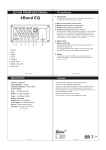
1
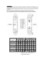
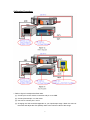
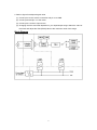
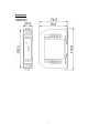
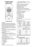
SG-3071 Isolated Voltage Input/Output Module User’s Manual Introduction The SG-3071 is a voltage input to voltage or current output signal conditioning module. It has 3000Vdc three-way isolation for input, output and power. And can change the input/output range via internal configuration switches. The SG-3071 has an LED display to show whether the SG-3071 is functioning correctly and has two VRs (Zero, Span) to calibrate the input/output range accuracy. The bandwidth of the SG-3071 is typically 3KHz. It’s easy to mount the SG-3071 on a standard DIN rail and can operate in environments with wide temperature range. Specifications Voltage input: Bipolar: ±5V, ±10V Unipolar: 0~5V, 0~10V Input impedance: 2MΩ Input bandwidth: 3KHz (typical)@-3dB Voltage output: Bipolar: ±5V, ±10V Drive: 10mA (max.) Output impedance: <50Ω Current Output: Current: 0 ~ 20mA, 4 ~ 20mA Current load resistor: 0~500 Ω (Source) General Three-way isolation: 1000 Vdc Accuracy: ±0.1% of full range (typical) Operation temperature range:-25°C~75°C Storage temperature range:-30°C~85°C Operation bandwidth: 3KHz Weight: 94 gram Supply Voltage Input Range: 10~30Vdc@24Vdc (Typical) Consumption: 1.80W (voltage output) 2.30W (current output) 1 Configuration The terminal wiring for the SG-3071 is shown in Figure A. Positive power terminals pins 7 and 9 are internally connected, as are negative pins 10 and 12. Power can be connected through the adjacent modules, making wiring much easier. The SG-3071 uses a power input range of 10~30Vdc. Table 1 shows the switch positions used to configure the input and output range. The I/O configuration switches are located inside the module. And can be accessed by removing the DIN-rail bracket covers by sliding them in the direction shown in Figure B. SG3071 Input To Output Range * Range (SW1) 2 3 ±10V/±10V ◆ ◆ ±10V/±5V ◆ ◆ ±5V/±5V ◆ ◆ ±5V/±10V ◆ ◆ 0~10V/4~20mA 1 ◆ 0~10V/0~20mA 0~5V/4~20mA 0~5V/0~20mA ◆ 4 Range (SW2) 5 1 2 3 4 5 ◆ ◆ ◆ ◆ ◆ ◆ ◆ ◆ ◆ ◆ ◆ ◆ ◆ ◆ ◆ ◆ ◆ ◆ ◆ ◆ ◆:ON Table 1: Input to output range (SW1、2) *Factory default setting 2 Calibration Procedure 1. Refer to figure C to adjust the offset value. (1) Connect pin7 to the +24Vdc connection and pin 10 to GND. (2) Connect pin8 and pin 11 to the meter. (3) Use wire to connect pins 1 and 2. (4) Changing the SW1 and SW2 depends on your input/output range. Watch the value of the meter and adjust the VR1 (ZERO) value to the minimum value of this range. 3 2. Refer to figure D to adjust the gain value. (1) Connect pin7 to the +24Vdc connection and pin 10 to GND. (2) Connect pin8 and pin 11 to the meter. (3) Connect pins 1 and 2 to input source. (4) Changing the SW1 and SW2 depends on your Input/Output range. Watch the value of the meter and adjust the VR2 (SPAN) value to the maximum value of this range. Block Diagram 4 Dimensions 5