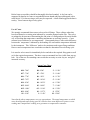
1
GK and EP Electric Kilns
manufactured by
Potclays Limited
Operating & Maintenance Instructions
Potclays Ltd, Brickkiln Lane, Etruria, Stoke-on-Trent, Staffs. ST4 7BP England
Tel: 01782 219816 Fax: 01782 286506
e-mail [email protected]
IMPORTANT NOTICE TO ELECTRICAL CONTRACTOR / INSTALLER
Although all electrical connections were securely tightened prior to dispatch it is possible as
a result of temperature cycling that some connections may work loose in the first few
firings. We therefore strongly recommend that after the first few firings a check is carried
out to ensure all electrical connections are tight, particularly the contactor and element tail
connections.
Unless otherwise specified (see kiln data plate) our kilns are designed to operate from 230
volts single phase or 415 volts three phase with neutral power supply. With 415 volt supply
each phase is connected to neutral so that each element takes only 230 volts.
Live, neutral and earth connector blocks to take the incoming electrical supply are located in
the rear connection chamber of the kiln. Access is gained by removing the back panel to the
kiln.
Where kilns can be operated from either 3 phase or single phase we use three line connector
blocks (each taking power to one of three banks of elements). If the kiln is to operate from
single phase supply, the incoming phase conductor should be connected to the centre line
connector block with a loop wire in suitably rated wire to each of the other two line
connector blocks. The single phase supply is in this way spread across the three line
connector blocks. Ensure all connections are fully and firmly made and that 'surplus' cable
or wires do not touch the wall of the kiln or are near element connections.
It is also advisable that these connections are checked at each service.
For immediate response to SPARES & SERVICE requirements please call
The service department
POTCLAYS LIMITED tel 01782 219816
Operation & Maintenance - EP and GK Electric Kilns.
Introduction
Congratulations upon your choice of a kiln manufactured by Potclays Limited. You can be
assured that it is made only from the finest materials and manufactured to the highest
standards.
Should you have any query, write or telephone 01782 219816 and ask for the Technical
Service or Sales Department as appropriate.
The instructions which follow will provide basic information about the installation, care and
operation of your kiln. More detailed useful information about the effect of heat on clays
and glazes, pottery faults, etc. will be found in 'The Electric Kiln, a Users Manual' by Harry
Fraser available from Potclays Ltd or via your local library.
Delivery Inspection
If it is not possible to thoroughly inspect the kiln for damage upon delivery then it is
essential you add the word 'unexamined' to the delivery note when signing for receipt of the
goods. Otherwise, upon delivery, check for obvious external damage, then open the kiln
door and check for internal damage. Minor surface blemishes in the brickwork are to be
ignored (since all bricks may have these and they are not detrimental). If there is any
damage you must notify both the carrier and ourselves within three working days.
Siting the kiln
1) Select a level, dry, well ventilated position, away from corridors and thoroughfares and with
room to allow easy loading and unloading of the kiln,. Ideally the kiln should be in its own
room.
2) Ensure that the floor is strong enough to carry the weight of the kiln. The kiln should be not
less than 250mm from the nearest wall and be a minimum of 750mm from the ceiling. A
gap on one side sufficient to provide easy access to a wall isolator and to the rear of the kiln
for servicing is needed.
3) Remove all flammable materials which might come into accidental contact with the kiln.
Electrical Installation
Unless otherwise specified on the kiln data plate, your kiln must be connected to a supply
which will provide a minimum 230 volts under normal operating conditions unless the kiln
has been fitted with elements designed for a lower voltage, Connection of the electrical
supply has to be made by your electrician to the terminals in the connection chamber at the
rear of the kiln, access to which is gained by removing the back panel.
Kilns designed for 230 volts and having a rating of 3.1 kW or less can be connected to a 13
amp fused plug and plugged into a standard UK domestic power socket. Kilns above 3.1
kW must be wired into the electricity supply using a cooker type switch or isolator box
suitably positioned on a wall adjacent to the kiln.
Kilns above 4.2 kW are wired so that they can be used from single or three phase supply. A
neutral is provided. For single phase connection, link the live terminals 1, 2 and 3.
In all cases it is very important that the supply fuse and the supply cable be correctly rated
for the kiln being installed. It is recommended that where possible the supply cable should
be run in conduit. Flexible conduit (Kopex or similar) is very useful because it has the
flexibility to permit some movement of the kiln for servicing purposes.
Kilowatt ratings and wiring diagrams are given in the Electrical Data section at the end of
this manual and appropriate data is repeated on the kiln data plate fitted to the front or side
of the kiln.
___________________________________________
EP & GK Series Kilns. General Information
Construction:
Frame
The framework is made of strong angle iron and flat section steel which is welded together.
The frame has been designed for a shelf to be positioned in the bottom section of the integral
kiln stand. Very strong hinges are used for the door and the design of these permits the door
to be lifted off to facilitate maintenance, repair, etc.
Brickwork
The finest available brickwork is used for the hotface. A special feature in the side walls is
that the bricks are specially jointed and cemented over 2/3rds of the brick contact face in
order to avoid element contact with cement to maximize element life.
Minor surface marks and fine surface cracks may be visible on some of the bricks. These
can be ignored as they are inherent from the manufacturing process of all bricks and are not
detrimental to their efficiency or performance. The bricks have phenomenal performance
but are easily damaged so take care not to contact with kiln shelves, props etc.
Back-up insulation
Behind the brickwork is back-up insulation selected for optimum efficiency. This will
normally be of ceramic fibre (of the non-hazardous body soluble type) plus layers of
calcium silicate slab or insulation brick - or a combination of these dependent upon location.
Elements
These are top grade Kanthal wire, conservatively rated for long life.
Spy & Vent holes
Spy holes are built into the kiln door and a vent port located in the roof. Additional
venting, if required, is available by the design of the safety switch which permits the door to
be marginally opened (`cracked’) but normally this will not be needed and is not
recommended.
Thermocouple hole
A hole is already drilled through the rear wall of the kiln and filled with ceramic fibre which
can easily be removed to permit thermocouple entry.
Energy Regulator & Indicator Lights
If fitted, an energy regulator controls the firing speed of the kiln by cycling the current to the
elements. The red light on the panel indicates power-on to the energy regulator, the other
(yellow) only illuminates when the energy regulator feeds power to the elements and it
therefore indicates cycling frequency. Larger kilns may have multiple energy regulators
each controlling a separate zone of the kiln. This provides zone control, enabling a regulator
to be turned up a little more or less than others in order to compensate for any temperature
variance in the kiln between one zone and another.
When using a temperature controller which controls firing speed (e.g. Firemaster) the energy
regulator(s) would normally be set to full-on position (unless it is necessary to reduce heat
input into one zone of the kiln compared to another).
Contactor Relay(s)
This is fitted in the underslung panel at the rear of the kiln. It enables the energy regulator
to switch the kiln electrical load and is also used to switch the load when temperature
controllers are used. Kilns having more than one energy regulator have more than one
contactor (usually one for each energy regulator).
Connection Chamber.
This is at the rear of the kiln and access is gained by removing the external rear panel.
Cable entry holes are made in the bottom plate.
Fuse
A fuse rated at 3amps is fitted in the connection chamber or in the fascia panel. It helps to
protect any temperature controllers fitted to the kiln. With certain controllers, two or more
fuses may be fitted.
Door operated safety switch
This will either be a switch actuated automatically by a rod (used on small kilns) or a
handwheel arrangement. With the latter, a spindle mounted on a bracket on the door of the
kiln and terminating in a rectangular box `spanner’, is entered through a rectangular hole in
the instrument panel. Rotating the handle one quarter turn clockwise then switches power
on to the kiln (assuming the mains power supply is switched on) and prevents the door from
being opened more than 13mm or so. The door can only be opened by firstly turning the
switch to its original position – which switches off the power to the kiln elements.
Kilns switching more than 60amps may alternatively be fitted with a trapped-key interlock.
Indicating pyrometer installation.
A hole is already drilled through the roof or rear wall of the kiln and filled with ceramic
fibre. Carefully remove the fibre and insert the thermocouple so that about 40mm of the
sheath projects into the firing
chamber. The collar supplied with the thermocouple can be lightly tightened to hold the
thermocouple at this position and the compensating cables fed back to the instrument.
The indicating instrument should be mounted upright but level and secured to a wall or
stanchion. With analogue instruments, a shunt wire is normally fitted across the connection
terminals (to dampen pointer movements during transit ) and this should now be removed.
Always ensure that the thermocouple is compatible with the instrument. We normally
supply instruments calibrated for use with 13% platinum rhodium thermocouples (type R).
They are therefore not suitable for use with 10% platinum rhodium thermocouples (type S),
or other types. Special compensating cable is used to connect the thermocouple to the
instrument The thermocouple negative wire should be connected to the negative terminal
on both the thermocouple and the instrument and the positive wire to the positive terminals.
With orange-coloured compensating cable the negative wire is white and the positive wire is
orange.
Under no circumstances must mains voltage be coupled to any thermocouple terminal.
Check the performance of the pyrometer with cones to ensure satisfactory working. Note
that this will show that the thermocouple is working but will not be an accurate indication of
temperature.
Pyrometric Controllers
Thermocouple connections as above.
Refer to circuit diagrams and separate instructions for each controller type,
Kiln Furniture
Kiln batts sufficient to cover the base elements and provide a loading platform were
included with your kiln. Position these so that there is even space all round with a gap in the
middle (if two or more batts).
Additional shelves are created by using three or four prop columns spaced equidistantly to
evenly support single shelves and four or five prop columns to support shelves consisting of
two batts. All prop columns should be placed so that their weight acts down over prop
columns below. It is best to use base supports and collars to spread the load where shelves
have two or more batts
Before batts are used they should be thoroughly dried and sounded. A dry batt can be
supported by hand at its centre or suspended between thumb and finger and tapped with a
metal object. If it does not ring a crack may be suspected. A dull sound suggests the batt is
not dry. Store batts on edge in a dry place.
Use of Cones
We strongly recommend Orton cones to be used in all firings. These collapse when they
have been heated to a certain point indicated by a number stamped on the side. They serve
as perhaps the best means of determining the end point of a firing and provide an invaluable
way of checking that temperature controlling instruments are working correctly. Cones
measure heat work however, not temperature. Consequently there is often some difference
between the `temperature’ indicated by the bending of a cone and the temperature indicated
by the instrument. This `difference’ tends to be consistent under repeat firing conditions
however and a temperature/cone correlation can thus be determined for each firing cycle.
It is usual to select cones for immediately below and above the required firing point as well
as for the required temperature. The three cones are mounted in a line visible from any spy
hole. Use of the new free standing cones avoids the necessity to set in clay etc. and gives
increased accuracy.
Orton Cone Chart
018 - 706C
08 - 950C
2 - 1150C
017 - 736C
07 – 978C
3 - 1160C
016 - 776C
06 – 995C
4 - 1176C
015 - 797C
05 – 1036C
5 - 1194C
014 - 836C
04 – 1055C
6 - 1230C
013 - 860C
03 - 1092C
7 - 1246C
012 – 880C
02 – 1110C
8 - 1259C
011 - 890C
01 – 1127C
9- 1270C
09 - 919C
1 - 1145C
10 - 1294C
Note that the above temperatures are very approximate. The actual temperature at which
cones bend depends upon firing speed It is usual to have some difference between a cone
reading and a temperature reading on a pyrometer or temperature controller.
Use of batt wash
If satisfactory the upper surface of each batt should be painted with batt wash mixed with
water to a thin, creamy brushing consistency. Sufficient should be painted on to cover the
batt without show-through. Periodic replacement of this coat will be necessary. Do not
paint props or any kiln brickwork with batt wash. Allow batt wash to dry before loading
ware and be careful to avoid transferring traces of batt wash on fingers etc. to the ware.
Test Firing
A drying-out firing should be done to a temperature around 800C. This must be done
slowly: about 40C per hour for the first 200C and not faster than 80C per hour
afterwards. Leave the vent plug out but reinsert it at about 700C. Leave one door
spyhole open throughout this firing
At least one other firing - empty or biscuit - should be done to build up a satisfactory
oxidised coat on the elements before carrying out a glaze firing. This initial oxidation
in a relatively clean atmosphere will prolong element life.
Trouble-Shooting
1) Kiln will not operate:
lf red power-on light does not come on:
a) Blown fuse in isolating switch box.
b) Fault in power supply to the kiln.
c) Faulty bulb in power-on light.
If red power-on light is on:
a) Kiln not set: Check door safety switch has been set (by inserting through hole to
engage switch and rotating quarter turn) and that any energy regulator is switched on.
b) Blown 3 amp secondary fuse in connection chamber or on fascia panel.
c) Faulty contactor or connections.
d) Faulty energy regulator or connections.
e)Faulty door switch or connections.
f)Temperature controller not set or faulty.
2) Kiln fires too slowly.
a)Failure of one or more elements.
b)Faulty energy regulator.
c)Low voltage.
d)Aged elements.
e)Failure of one phase in multiphase supply situations. Check supply fuses.
3)
Kiln fires unevenly.
GK/EP kilns are designed to fire with less than 300C difference top and bottom, front and
sides at e’ware or stoneware temperatures. Most times the difference will be less than 100C
Uneven temperature distribution may arise if:
a) Kiln loaded very unevenly.
b) lnsufficient air circulation to bottom elements : pack up the base kiln batts to
provide greater air clearance if the base is too hot.
c) Overlarge kiln batts. There should be good clearance (minimum 15mm all round
between shelf and kiln walls.
d) Worn vent plug allowing cold air to enter.
e) Worn or damaged contact face between door and kiln allowing draughts to enter.
f) Failure of one bank of elements (note failure of one will prevent a whole bank of
elements from working.)
Note that with kilns fitted with several energy regulators, the energy regulator controlling
the hottest zone can be switched to a lower setting than the others in order to pass less
energy into the hot zone and thus compensate for temperature variance.
Cracking of Brickwork.
Some surface cracking on hot face brickwork may arise during use. Such cracking is quite
common, especially when kilns are rapidly fired but it is no detriment to kiln performance
and can be ignored. If wide cracks develop or if brick courses eventually need pointing,
this can be corrected using Potclays refractory insulation cement. Do not use inferior
cement.
Kiln servicing& repair
We can carry out regular servicing of your kiln ( and others) as required. Such visits
include full electrical checks and any necessary preventative maintenance or repair.
Please bear in mind that we are kiln users as well as kiln manufacturers. If you
have any kiln or firing problems, please contact us. Speaking with one of our
experienced technicians will likely enable problems to be resolved more quickly.
LOADING THE KILN FOR A BISCUIT FIRING.
Load only bone dry clayware. A satisfactory test is to place the ware against the cheek. If it
feels cool, it is still damp. Moist ware if fired will explode and ruin not only that piece but
others as well.
Many more clayware than glazed pieces can be stacked in a kiln. Clayware can be set
directly on kiln shelves, can touch and be stacked inside other clayware. Allow at least
13mm between pieces and kiln walls.
During the biscuit firing pieces should be level to avoid unequal strains. This is especially
true of flat pieces which tend to warp more than others. Small pieces may be placed inside
larger ones, but heavy pieces should not be placed on top of thin or lighter ones: too much
weight will cause warping or cracking. Do not stack bowls and dishes over three high.
Cups and tumblers which warp easily can be "boxed". That is, one piece is placed upside
down on the other so the rims rest one on the other. Place a pot lid in position on the pot or
on the shelf near it so the two pieces will be fired under the same conditions. Variation in
temperature can cause a difference in shrinkage.
LOADING THE KILN FOR A GLAZE FIRING.
Actual loading of glazed ware is quite different from clayware. Since glaze becomes molten
during firing, it will adhere to anything it touches. Pieces must be spaced at least 3 mm
apart and 12-15 mm from walls. All pieces which are glazed on the bottom must be placed
on stilts etc. to raise them off the kiln shelf. Pieces which are "dry footed" can be placed
directly on the shelf. "Dry footing" means that the piece has not been glazed on the area
where it will touch the shelf, or that glaze has been wiped off that area with a damp sponge.
Large, flat pieces should be "dry footed" for they will almost invariably warp or slump if
placed on stilts. Stoneware and porcelain pieces inevitably are dry footed for these must be
placed flat on shelves to prevent warping.
If a lid is to be fired on a piece to prevent warpage or deformation, any glaze must be
thoroughly cleaned from the lid flange and skirt and from the surface where it rests.
Don't forget the cones!
FIRING PROCEDURES.
Before commencing biscuit and glaze firings the kiln should have been test fired as
described previously to check for correct working.
______________________________________________
There is no warranty to cover against over firings. It is important that you check
firings using Orton cones, and have your controller regularly serviced. Always check
soon after the time a kiln should have been switched off that switch off has occurred.
______________________________________________
BISCUIT FIRING.
Biscuit firings are normally taken up to about 1000ΟC for articles made from Red clay,
Earthenware, Stoneware and Porcelain where the glaze is to be fired higher than the biscuit
ware. In this event a glaze is then selected which has a firing temperature which matures the
glaze and the body at the same time. Sometimes with earthenware it may be desirable to use
the industrial technique in which the clay ware is fired up to the maturing temperature of the
clay used (e.g. 1120 to 1150C for White Earthenware) and a lower temperature glaze then
applied. In the case of Bone China this is always biscuited to maturity (around 12400C) and
glaze fired lower (1050 to 10800C).
Potclays fine doll porcelains should be biscuit fired around 1220C and do not need glazing.
China paints can be applied directly on to the biscuit.
Biscuit firing is best done over a cycle of not less than 7 hours and preferably longer (8 to 10
hours) - especially with wheel thrown wares or those with thicknesses exceeding 10mm.
Bone China would be about 10 to 13 hours firing to 1240C and perhaps then soaked for 1/2
hour or more at maximum temperature if extra translucency is needed.
A suggested biscuit firing procedure for manual control of the firing cycle (i.e. controller
not fitted) and to 10000C is as below. (For automatic firings using a temp.controller, see
page )
1)
Check all switches off.
2)
Switch on at Isolator and set door switch.
3)
Set Energy Regulator to about 10 - 20% for 2 - 3 hours. Vent Plug out.
4)
Set Energy Regulator to 40% for 2 - 3 hours. Vent Plug out.
5)
Set Energy Regulator to 70 - 90%. Replace Vent plug.
6)
At 10000C or when 06 or 05 cone bends, shut off the kiln at both Energy
Regulator and wall Isolator and leave to cool.
Check the ware and firing time. If the firing was completed in less than 8 hours, leave the
kiln on an intermediate setting of the energy regulator for a longer time on the next firing.
GLAZE FIRINGS.
At the beginning of a glaze firing the venting period can be shorter than for a biscuit firing
and the rate of firing can be faster. Firing speed should generally be between 100 to
1400Cper hour. An average 1000Cper hour would be a good initial target.
A suggested procedure for manual control of the firing cycle is as below. (For kilns fitted
with automatic temperature controllers, see next page).
1)
Check all switches are off, cones in position and door closed. Remove vent plug.
2)
Set door switch and switch on at Isolator.
3)
Set energy regulator at 10-20% for 1 hour. ( Vent plug out.)
4)
Set energy regulator at 40-50% for 2 hours. Replace vent plug.
5)
Set energy regulator at 80- 100%.
6) Switch off or 'soak' at required glaze firing temperature for 1/2 hour (by turning
back the energy regulator). Leave to cool.
Cooling can be speeded if necessary by removing the vent plug for 15 mins or so after
switching off a glaze firing but it is generally better to leave the kiln to cool naturally until
the temperature is below 1000C when the kiln door can be 'cracked' open very slightly and
increased in stages.
Once-Fired Ware
This should be fired at the rates suggested for biscuit firings, or even slower, the firing being
extended to glaze maturity. Care should be taken to fire very slowly over the initial 2000C
(to avoid glaze crawling) and especially from 600 to 10000Cto ensure burning away of
carbonaceous material (to avoid bloating at high temperature with stoneware bodies).
Decoration Firings.
Firing of overglaze colours (china paints etc.) produces fume from the burning away of
media used in colour application. Consequently the vent needs to be left open until the
odour of burning media has disappeared (normally between 400-5000C).
A suggested manual procedure is:
1)
Check isolator and all switches off. Cones in position.
2)
Switch on at isolator and set door switch. Remove Vent Plug.
3)
Set Energy Regulator at 20% on for 1-2 hours. Vent Plug out.
4)
Set Energy Regulator to 40% for 2 hours. Vent Plug out.
5) Set Energy Regulator at 60-80%. Replace vent plug when odour of burning
media disappears or when 6000C temperature reached whichever is earlier
6) Switch off at required point (normally about 750,C for china paints). Leave to
cool and do not open until pieces are cool enough to hand-hold.
Automatic firings - using a temperature controller.
The firing procedure when an automatic controller is fitted depends upon the type of
controller. There are basically two types of controller: one which does not control the firing
speed but gives automatic cut off at end of firing (e.g. Limitronic, Kiln Sitter etc.) and one
which controls the complete firing cycle including firing speed and auto shut off
(e.g.Firemaster, Hobbymaster etc.)
With the first type, the firing speed has to be controlled manually by adjustment of energy
regulators as set out in the previous pages. With the fully automatic type the controller
carries out the function of the energy regulators in controlling the firing speed. If an energy
regulator is fitted to the kiln this should be set fully on for firing since the usual way of
fitting a controller is by wiring the output to the kiln contactor via the energy regulator. In
theory the energy regulator is then superfluous to the kiln operation but in practice is a
`back-up’ in that the kiln can be fired manually (with a little wiring adjustment) in the event
of controller malfunction. With many kilns, energy regulators are not fitted when automatic
controllers are to be used.
Separate instructions are supplied for the controller supplied with your kiln and these should
be carefully read to familiarize yourself with its correct operation. Nevertheless, reference
should also be made to the manual firing procedures outlined previously since these indicate
suggested firing speeds, removal of vent plugs etc.
If in any doubt whatever, please telephone Potclays Ltd (01782 219816). We will be
pleased to help
SOME DEFECTS IN FIRED WARE.
Cracks in Biscuit Ware
Cracked biscuit pieces are often best discarded. However, minor cracks on valuable items
may be filled with ceramic stopping and the piece then glazed and finished in the usual way.
Stopping can be made using a paste of powdered biscuit ware and sodium silicate or a
mixture of powdered biscuit ware,a little glaze, a little glaze binder or gum, and water.
Most biscuit ware cracks originate from cracks or stresses present in the clayware. Check
that drying is not too quick and that large pieces can shrink easily across the surface on
which they were placed (a layer of paper or sand often assists). Check pieces are not
physically damaged before being placed in the kiln.
Pieces of varied thickness may warp and crack if not dried carefully. 'S' cracks in the base
of pieces are often caused by the outer walls drying first and base drying afterwards whilst
the outer walls are rigid (due to having completed their shrinkage). Consequently the base
is then under stress and cracks as it shrinks.
Cutting and fettling tools must be sharp to give smooth cut on trimmed surfaces although it
is often best to finish off with a damp sponge especially if fine cracks develop along the
trimmed edges.
Too rapid firing up to 4000C can cause cracks to form. Very heavy spouts, handles etc.,
can sometimes crack away if the design is not satisfactory (clay props could be used to
prevent such cracking). Similarly, badly supported ware may crack at the point of stress).
Cracks in Glazed Ware: Dunting.
Dunts are cracks due to thermal stress or shock which pass right through the article. If the
edges of the crack are sharp it was made during the cooling. If they are rounded or smooth
this indicates the crack occurred during heating. Remedies include slowing the heating or
cooling rate, avoiding draughts around the kiln, ensuring that the vent plugs are left in
position during cooling, and never force -cooling the kiln. Indeed with some complex
pieces it may be necessary to slow down the cooling rate by putting the kiln back on again
(but at a low heat setting) after switching off, or from red heat downwards.
Especially with complex shapes or with pieces having a large flat base (such as casseroles) it
is advisable not to place them flat on the kiln shelf but to use stilts, saddles etc., to lift them
slightly clear of the shelf. This gives more even heat distribution when firing.
Pinholing in Glazes.
Tiny holes or blisters are usually caused by gases given off during the glost firing arising
from the biscuit ware, from the glaze itself and from air bubbles trapped in the glaze layer
during application. The higher the biscuit firing the less the amount of gas generated from
this source during the glaze firing. The more fluid the glaze when molten or the longer the
glaze remains in its fluid molten state the greater the ability for the glaze to flow to fill in the
pinholes in its surface. Raising the firing temperature of an underfired glaze may therefore
cure pinholing. 'Soaking' the glaze (i.e. holding glaze firing temperature for 1/2 hour or
so) is a good remedy. Overfired glaze however can boil and emit bubbles (much as does
water when boiling). Too rapid glaze firing may not allow bubbles to clear from the glaze
before they become imprisoned as the glaze cools and solidifies (fire slower or 'soak' to
cure). Glaze applied much too thinly will result in many tiny pinholes which can be
corrected by reglazing and refiring.
Crazing of the glazed ware.
Crazing is caused by a difference in the thermal expansion coefficient. of the body and the
glaze applied onto it. Matching clay and glaze from the same source of supply is therefore
recommended. Fast cooling can promote crazing and ideally the ware should cool slowly to
room temperature in the kiln before being removed. Too- thick glaze also can result in
crazing. Crazing can often be corrected by refiring the ware one or two cones hotter than
the previous firing and this can be done with ware which crazes some time after being fired.
Generally one should ensure that either during the biscuit or during the glaze firing the ware
is fired at least to the minimum temperature recommended for the clay body being used refer to the manufacturers specification.
Crawling in Glazes.
When a glaze pulls away from the body in firing into balls and drip-pattems, the symptom is
called crawling, and the remedy is usually a thinner coat of glaze. Too thick applications of
glaze may develop stresses along a curved surface in drying. Cracks appear in the dried
glaze coat, which become fissures in firing, and “crawl" into lumps of glaze, leaving the
body bare. Sometimes, a second coat of glaze touched in over the exposed body and refiring
may correct the defect. The best corrective measure is a preventative one; namely a thinner
glaze application in the first place. Dust or a greasy surface on the biscuit may also cause
crawling.
Crawling is very common on once-fired ware and initial heating must be very slow to avoid
this, the glaze tending to crawl due to over-fast release of steam from the clay body.
Glaze Craters.
Craters are often due to underfired glaze and can be remedied by using a grindstone to
remove `high spots’, dabbing glaze into the craters and then refiring to a hotter temperature.
Other Glaze Surface problems.
A shiny glaze which fires dull is probably underfired or, with some glazes, has been cooled
very slowly over the first 1500C after switching off, or has had an excessive soaking period.
Matt glazes which fire shiny have probably been overfired or in some cases, cooled too
quickly over the first 2000C or so after the kiln is switched off (remedy is then to 'fire
down'). Applying the glaze too thinly may also result in the glaze firing shiny
A thin application of glaze may also cause opaque glazes becoming semi –opaque. A loss
of opacity can also result from cooling too quickly after switching off. Mattness and opacity
are created by crystal growth- and crystals need time to grow in the molten glaze plus a
glaze layer thick enough for them to grow in.
Spit-Out
A mass of tiny pinholes which are rough to the touch and give a rough surface on overglaze
decorated ware after firing is caused by the ware containing trapped moisture which bursts
through the softened glaze during enamel firing. The problem is much more common with
earthenware and other porous wares but very unlikely with vitrified wares such as bone
china. Avoid old ware if possible, or fire the piece before decoration to see if spit-our
occurs.
Affected pieces may sometimes be reclaimed by refiring the piece to glaze firing
temperature and then redecorating. Sometimes grinding away the glaze from a small area
on the back of the piece will allow trapped steam to escape there instead of bursting through
the glaze. The ground area can then be painted with a clear enamel flux to seal it when
fired.
Faded Transfer Decals.
Check the transfer manufacturers recommendation. Fading is generally due to overfiring
but occasionally also to underfiring. Little can be done to save an overfired transfer.
Further Information
'The Electric Kiln, a Users Manual'
'Ceramic Faults and their Remedies'
(Both by Harry Fraser, published by A & C Black.
Potclays Ltd regularly hold one day seminars in ceramic craft technology including `Glazes
and Firing’ and `Kilns operation, control, and maintenance’. Tel 01782 219816 for leaflet.
Electrical Information.Kilowatt Rating.
This is detailed on the data plate fixed to the front or side of the kiln. The kiln model number and serial
number is also given on this name plate and should be quoted in event of any electrical query.
Wiring details.
All kilns above GK28 and EP38 since are wired similarly to GK60 and EP73. The only difference is the
number of elements served by each line. The GK80 for example has wiring split so that LI supplies element.
1,2,3,4 and 5; L2 supplies elements 6 to 11 inclusive and L3 supplies elements 12 to 16. Kilns larger than
GK63 and EP72 however may be fitted with two or more energy regulators (see catalogue specification). In
this event the electrical feed from the safety isolating switch is supplied to each contactor served by an energy
regulator.
Where an automatic controller is used the kiln may alternatively be supplied without energy regulator(s), the
controller operating the contactor directly.
See electrical drawing supplied separately.
Elements.
Most kilns have identical elements but some have differently graded elements in certain positions. In the
GK80; for example, elements 6 to 11 inclusive are rated differently to the other ten elements. When ordering,
please specify the position of the element. This is determined when viewed from the front of the kiln, by
allotting number 1 to the top left hand element hairpin (ie two coils of one continuous length held in two
grooves). The element hairpin below is numbered two and numbering continues down the left hand side,
across the hearth and up the right hand wall terminating in the element at the top right hand side.
Electrical Installation.
With three phase power supply, connect the phase conductors respectively to terminals 1, 2 and 3 with neutral
to 4 (and earth to appropriate connection point). These connection terminals are located in the connection
chamber at the rear of the kiln. For single phase supply, connect to 2 with wire link to 1 and 3. (Sometimes it
is easier to link on the kiln side of the connectors).
Wiring of Controllers.
Temperature controllers must not switch the full load of the kiln but must be wired to operate the holding coil
on the kiln relay. Power supply to the controller should therefore be picked up from terminal 6 on the
Ancillary Connection Block (rear of kiln) and the connecting link between 6, 7 and 8 removed. The controlled
output from the controller should then be taken to terminal 8,neutral being taken from terminal N.
Multi-Socket Wiring.
Where a multisocket is used for temperature controller connection to the kiln we adopt the following
convention: - Brown on socket (L) to No 6 on kiln; Blue (N) to Neutral on kiln, YeIIow (return) to No 8,
Red to No 7. White (-) and orange (+) thermocouple wires are also attached.,
Please bear in mind that we are kiln users as well as kiln manufacturers. If you
Have any kiln or firing problems, please contact us.
Speaking with one of our
Experienced technicians will likely enable problems to be resolved more quickly.
Loading your kiln
General Considerations.
Follow these instructions when loading your kiln:
1) Load only bone dry green ware into the kiln. Wet ware may crack on firing or even
explode resulting in damage to other ware. Ceramic cast green-ware should be dried for at
least three/five days with larger or thicker pieces requiring even longer. Glazed ware should
dry for six hours before firing.
2) Plan the load before starting. Arrange the load so that thick and thin walled pieces will
be mixed throughout the kiln to give an even load
3) Allow at least one element groove between every shelf. If your kiln has a blank
element groove, let at least two element grooves contribute to the heating of the blank space.
4) Keep shelves and ware at least 13mm from the wall of the kiln. At least one element
groove must be between the top shelf and the top of the kiln.
5) lf large flat pieces are being fired, the edges should be placed between elements. This
may eliminate possible cracking from uneven heating.
6)
Place the shelves in the kiln carefully so the walls of the kiln will not be damaged.
7) We strongly recommend that cones are used for firing. These should be placed 70mm
or so behind the observation hole. Check that they are visible and that they will not
collapse against ware or kiln props etc. With initial firings it is important to rely on cones to
control the end-point of firings, using any temperature control instrument only as a reference
until it can be seen by cone results that the instrument can be relied upon. The continued
use of cones is recommended however since they indicate the effect of heat work and can
indicate hot or cold areas in the kiln.