1
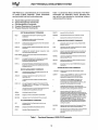
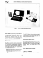
iPDS™
PERSONAL DEVELOPMENT SYSTEM
•
II
•
•
•
•
Completely integrated computer
system packaged in a compact
rugged enclosure for po~tability
•
640 K byte Integral flexible disk
drive; expandable to 1.28 million
bytes
Comprehensive design tool for 8 bit
Intel microprocessors
II
PowerfuiISIS-PDS disk operating
system with relocating
macro-assembler, and CRT -based
. editor
Microprocessor Emulator (EMV)
functions
Dual processing capability
Expandable using standard
M ultimodule™ cards
Desk top compute~ for CP/M* based
applications
•
Optional high level languages
Fortran 80,PL/M 80, PL/M 88/86
and Basic
•
•
•
Software compatible with previouf
Intellec systems
PROM programming functions
Bubble Memory option.
The iPDS Development System is a completely integrated computer system supporting the development
of products incorporating Intel 8 bit microprocessors or microcontrollers. Used with its optional emulation
vehicles (EMVs) and iUP PROM Programming Personality Modules, the iPDS system provides comprehensive support for integrated hardware and software development, product testing during manufacture, and
customer support after the product is in the field. The unit is designed with portability in mind permitting
the iPDS Development System to be conveniently transported around the laboratory and into the field. Extensivesoftware is available thereby simplifying and speeding up product development. The software is
designed to make the iPDS system easy to use for the novice as well as satisfying the needs of the experienced user. Used with the optional CP/M operating system, the iPDS system becomes a desk top
computer that can execute CP/M compatible application programs.
The following are trademarks of Intel Corporation and its affiliates and may be used only to identify Intel products: BXP. CREDIT, i, ICE, ICS ..im, Insite, Intel, INTEL, Intelevision,
Intellec, iPDS, iSBC, iSBX, Library Manager, MCS, MAIN MUL TIMODULE, Megachassis, Microamp, MUL TIBUS, Plug-A-Bubble, PROMPT, Promware, RMX, UPI, ",Scope, System
2000, Micromainframe, and the combination of MCS, ICE, iSBC, iRMX or iCS and a numerical suffix. Intel Corporation Assumes No Responsibility for the use of Any Circuitry
Other Than Circuitry Embodied in an Intel Product. No Other Patent Licenses are Implied.
AUGUST 1982
© INTEL CORPORATION, 1983
Order Number: 210390-002
1-6
iPDS™ PERSONAL DEVELOPMENT SYSTEM
graphics are defined. If the Optional Processor
Board is installed, the second processor shares
the CRT with the base processor. The bottom patt
of the screen is assigned to the processor communicating with the keyboard. The top part of the
screen displayed in reverse video is assigned to
the other processor. The number of lines appearing on the screen for each processor can be completely controlled by the user via special function
keys.
FUNCTIONAL DESCRIPTION
Hardware Components
The iPDS case comprises two high impact, shock
resistant, poly-carbonate plastic enclosures, that
when fitted together, provide a compact and fully
enclosed unit. The main enclosure houses a CRT,
flexible disk drive, power supply, and base processor printed board assembly. The second
enclosure houses the keyboard. On the right side
of the unit a spring loaded door allows insertion of
an emulator module or an iUP PROM programming
module. On the top, a hinged panel covers the
storage space for cables and plug-in modules.
The carrying handle is attached to the front of the
main enclosure and folds away when the system
is in use. In the closed position, the iPDS system
is 8.15" high, 16" wide, 20" long, and conveniently
fits under an airline seat. The basic unit weighs 27
pounds.
KEYBOARD
The keyboard is housed in a separate enclosure
and a flat shielded cable connects it directly to
the keyboard controller on the BPB. This 5" cable
provides the flexibility to place the keyboard in a
comfortable operating position relative to the
main enclosure. A total of 61 Keys include a typewriter keyset, cursor control keys, and function
keys. Auto repeat is available for all keys and is
implemented by the keyboard controller. If the Optional Processor Board is installed, it shares the
keyboard with the base processor. Initially, the
keyboard is assigned to the base processor. It can
be assigned to the optional processor by pressing
the special function key, FUNC-HOME. Subsequent use of the FUNC-HOME key alternates the
keyboard aSSignment between the two
processors.
BASE PROCESSOR PRINTED BOARD
ASSEMBLY-BPB
The Base Processor Board (BPB) contains the
powerful 8085A microprocessor, 64K bytes of
RAM, CRT/keyboard controller, floppy disk
controller, serial I/O port, and parallel I/O port..
There are interfaces for connection to the Optional
Processor Board, Multimodule Adaptor Board,
and the EMV/PROM Programming Adaptor Board.
INTEGRAL FLOPPY DISK DRIVE
The integral floppy disk drive is a 5 1/4", doublesided, 96 tracks-per-inch drive. Diskettes are written double-sided, double density and provide 640
K bytes of formatted storage in the built-in drive.
The floppy disk controller located on the BPB is
based on the INTEL 8272 floppy disk controller
chip, and can control one additional drive. The
ISIS-PDS operating system supports the disk
drives. If the Optional Processor Board is
installed, the integral disk drive is shared by the
two processors or it can be exclusively assigned
to one of the processors. When shared, only one
processor can access a drive at a time. However,
the disk drive sharing is transparent to the user
since the ISIS-PDS operating system controls the
accessing of the drive and automatically resolves
file contention.
INTEGRAL CRT
The CRT is a 9 inch green phosphor (P42) unit
that displays 24 lines of 80 characters/line with a
nominal 15.6 KHz vertical sweep rate. The CRT
controller, based on an Intel 8085 and 8275 Programmable Controller Chip is located on the BPB.
A single cable containing the signals, power, and
ground connect it to the CRT. The contrast adjustment is accessible at the rear of the unit. A pull
out bail allows the CRT to be placed in a comfortable operating position of 24 degrees to the
horizontal. The standard ASCII set of 94 printable
characters is displayable, including upper and
lower case alpha characters, and the digits 0
through 9. Another 31 characters for character
1-7
iPDS™ PERSONAL DEVELOPMENT SYSTEM
INPUT /OUTPUT
interface is implemented with an Intel 8255 Programmable Parallel Interface chip. A maximum
transfer rate of 600 cps is supported.
The iPDS Development System contains two I/O
channels located at the rear of the base enclosure
and wired to the I/O ports on the Base Processor
Board. The serial channel is an EIA RS-232-C interface for asynchronous and synchronous data
transfer and is based on the Intel 8251 USART
and 8253 timer. The interface can be software
configured using the SERIAL command. Full
duplex asynchronous operation from 110 to 19.2K
baud is selectable.
Software Components
ISIS-PDS OPERATING SYSTEM
The ISIS-PDS operating system included with the
basic iPDS system is designed with a major
emphasis on ease of use and simplification -of microcomputer development. It is based on the
proven ISIS II operating system available on all Intellec Microcomputer Development Systems:
The parallel I/O interface is an 8 bit parallel I/O
port supporting a Centronics type printer. The
EXTERNAL
FLOPPY
CONNECTOR
RAM
CONTROLLER
DYNAMIC
RAM
64K
INTERNAL DRIVE
5114" FLOPPY
640KB
EMV/PROM
PROGRAMMER
PORT
BOOTI
DIAGNOSTIC
2K
MUL TIMODULE
PORT
SERIAL
INTERFACE
PROGRAMMABLE
BAUD RATE
GENERATOR
OPTIONAL
PROCESSOR
PORT
0950
Figure 1.
iPDSTM Block Diagram
1-8
iPDS™ PERSONAL DEVELOPMENT SYSTEM
ISIS-PDS has a comprehensive set of commands
to control system operation. These commands
can be divided into five functional groups.
•
•
•
•
•
Table 1 summarizes these commands. The HELP
commands are especially useful, providing the
user with on-line assistance, eliminating frequent
referencing of the manual.
System Management Commands
Device Management Commands
File Management Commands
Program Development Commands
Program Execution Commands
SYSTEM MANAGEMENT COMMANDS
displays help Information for operating system
commands.
HELP
OELETE
removes files from the disk.
RENAME
changes the filename and/or extf:<nsion of a file.
displays the contents of a file on the screen.
@
displays the version number of the current
Command Line Interpreter.
PROGRAM DEVELOPMENT COMMANDS
FUNC-R
software resets the processor to which the keyboard
Is currently assigned.
LIB
allows the user to manage a library of MeS_80/85
program modules.
FUNC-S
switches the CRT display speed between a slow and
fast speed.
LINK
combines a number of object modules into a single
object module in an output liIe.
FUNC-T
switches the keyboard between typewriter mode
,and locked upper case mode.
LOCATE
converts relocatable object programs into absolute
object programs by supplying memory addresses
throughout the program.
HEXOBJ
converts a program from hexadecimallile format to
absolute object format.
OBJHEX
converts a program from absolute object format to
hexadecimal file format.
OEBUG
provides a minimum set of 8080/8085 debugging
commands.
FUNC-HOME switches the current foreground and background
processors.
increases the display for the foreground processor
by one line and decreases the background
processor display by one line.
FUNC-I
decreases the display for the foreground processor
by one line and increases the background processor
display by one line.
FUNC-I
PROGRAM EXECUTION COMMANDS
DEVICE MANAGEMENT COMMANDS
< filename>
IDISK
initially prepares disks and bubble memory for use
with the operating system.
ASSIGN
displays or assigns the mapping of physical to
logical devices.
SUBMIT
•
re-assigns the system output to the CRT display
screen.
FUNC < n >
changes the system input from the keyboard to the
filenamedJOB<n>.CSOwhere <n> Is a one-digit
number from 0 to 9.
assigns a row of multimodules to a processor.
OETACH
releases a row of mullimodules from a processor.
stores a sequence of frequently used ISIS
commands in a job file as they are entered from the
keyboard without executing them until the sequence
is completely entered. Two job files. ABOOT.eSO
and BBOOT.eSO, deserve special mention. II either
of these files is present (ABOOT.CSO for Processor
A and BBOOT.CSO for Processor B) when the
system is initialized, commands are automatically
executed from the file. This feature can be used to
configure a system.
ENOJOB
stops the automatic execution of commands from a
JOB lile and returns control to the keyboard.
ESC
edits the previously entered or the current command
line and allows the new command line to be
executed.
FILE MANAGEMENT COMMANDS
OIR
displays a list of the files stored on a disk or on
bubble memory.
ATTRIS
displays and modifies the attributes of a file.
COPY
transfers files and appends files.
is a fast form of the SUBMIT command. One
command line is read from the SUBMIT file,
transformed into an ISIS command in memory, and
executed. No intermediate file is created.
JOB
initializes the serial 110 port.
ATTACH
reads an input SUBMIT file, creates a command file
containing ISIS commands, and executes
, commands in sequence from the file created.
reads ISIS commands from a disk job file and
executes them in sequence. The / command is also
considered a device management command.
changes the system Input from the keyboard to a file
or device which is specified by the user.
SERIAL
loads and executes the object program named
<filename>.
Table 1 .. Functional Summary of ISIS-PDS Commands
1-9
iPDS™ PERSONAL DEVELOPMENT SYSTEM
ISIS-PDS CREDITTM TEXT EDITOR
be used to troubleshoot the assembler-produced
machine language using features such as software breakpoints, single step execution, register
display, disassembly, and I/O port access. This
reduces the time spent troubleshooting the software and supports modular program development.
Included with iPDS is the INTEL CRT-based text
editor, CREDIT. It is usedto create and edit ASCII
text files on the Intel Personal Development
System. Once the text has been edited, it can be
directed to the appropriate language processor
for compilation, assembly, or interpretation.
CREDIT features, shown in Table 2, are easy to
use and simplify the editing and manipulation of
text files.
UTILITIES
Utility programs included with iPDS are: DEBUG,
LIBRARY, LINK and LOCATE. These programs aid
in software development and make it possible to
combine programs and prepare them.for execution
from any memory location.
The two editing modes in CREDIT are screen
'mode and line mode. In screen mode the text
being edited is displayed on the CRT and corrected by either typing the new text or using the single
stroke character control keys. Single character
control keys are used for changing, deleting,
inserting, paging forward, and paging backwards.
DIAGNOSTICS
The iPDS includes system diagnostic routines
executed during system initialization. These
routines verify the correct operation of the system
and aid the user in fault isolation. Any failures in
the basic system components, base processor,
CRT IKeyboard, optional processor, or the power
supply are indicated by four diagnostic LED indic'ators mou'nted on the base processor boards.
These LED's are viewed through the spring loaded
door on the right side of the unit. When basic
system components are operational, additional
errors are indicated by messages to the CRT display screen.
In command line mode, high level commands are
used for complex editing. Examples of the functions available in the command line mode are
searching, block moves, copying, macro
definitions, and manipulating external files.
8080/85 MACRO ASSEMBLER
The iPDS also includes the INTEL 8080/85 Macro
Assembler. This macro assembler translates programs written in 8080/8085 assembly language
to the machine language of the microprocessor. It
also produces debug data. The Debug utility can
CREDITTM Editor features two editing modes: cursor-driven screen editing
and command line context editing
CRT Editing Includes:
•
•
Displays full page of text
•
•
•
Type-over correction and replacement
•
•
•
•
•
•
•
•
•
•
•
Single control key commands for insertion, deletion,
page forward and backward
Immediate feedback of the results of each operation
The current state of the text is always represented
on the display
Command Line Editing Includes:
•
String search and substitute
•
•
String delete, change. or insert
Block move
Table 2.
Block copy
User-defined macros
External file handling
Change CREDIT features with ALTER command
Conditional iteration
User-defined tab settings
Symbolic tag positions
Automatic disk full warning
Runs under ISIS-II SUBMIT facility
bption to exit at any time with original file intact
HELP command
Summary of CREDITTM Editor Features
1·10
iPDS™ PERSONAL DEVELOPMENT SYSTEM
After ISIS-PDS is loaded and started, additional
confidence tests are available to verify correct
system operation. These tests included on the
system disk, run as utilities under the operating
system and can be selectively executed to verify
individual functions on the main processor board,
optional processor board, bubble memory Multimodules and EMV/PROM Programmer Adaptor.
Both processors share the keyboard, the CRT display unit, the disk drives, and the multimodules.
Serial or parallel I/O ports can be added to the optional processor' through iSBX multimodules.
Each processor runs the ISIS-PDS, operating
system and applications programs in its own 64 K
byte memory space, independent of the other
processor. Special hardware function keys are
provided to facilitate procedures necessary in the
dual processing environment. These procedures
include independent initialization of each
processor, sharing of the CRT display, and assignment of the keyboard. The ISIS-PDS commands
facilitate sharing of disk drives, multimodules,
and files.
iPDS™ HARDWARE OPTIONS
Add-On Mass Storage
Mass storage can be increased by adding one external flexible disk drive. This adds 640 K bytes of
formatted mass storage. The maximum disk storage available on iPDS is 1.28 M Bytes. The optional/drive is vertically mounted and housed in a plastic enclosure with its own power supply. A 20"
cable connects the optional floppy drive to the external disk drive connector on the rear of the iPDS
system.
Emulation Vehicles (EMVs)
Emulation vehicles (EMVs) for use with the iPDS
Devlopment System, are available for debugging a
variety of Intel microprocessor families. Emulators
consist of hardware and software. The- EMV hardware is inserted into the EMV/iUP Personality
Module port of the iPDS. The optional EMV/Prom
Programming Adaptor Board is required to install
the EMV's. The emulator software runs under the
ISIS-PDS operating system and provides the
user's interface to the emulator.
The iPDS system also supports Intel's iSBX-251
Bubble Memory Multimodule. A maximum of two
bubble multimodules can be added. Each contain
128 K bytes of non-volatile memory. Bubble
memory Multimodules can only be added to a
system containing the Multimodule Adaptor,
Board. The bubble memory is treated by the ISISPDS and CP/M operating system as an additional
disk drive with the same file structure and directory structure as a diskette. The bootstrap ROM is
programmed to boot the operating system from
the bubble. The iSBX-251 has no moving parts, '
making it ideal for applications where ruggedness
is an important consideration. The bubble
memory is also recommerided for systems requiring portability, since it is completely enclosed in
the iPDS main unit.
An EMV contains features used to debug microprocessor designs quickly and efficiently. It provides a controlled environment for ~xercising a
user design and monitoring the results. It exactly
duplicates the behavior of a target micro":
processor/microcontroller in the user's prototype
system while providing information to the user to
aid in integrated hardware and software
development. EMV's provide features for real time
full speed emulation as well as single step execution of a user's design. Breakpoint features allow
the user to specify a portion of the program to execute and then stop for interrogation. During
execution, the EMV automatically collects execution history in the trace buffer. Once stopped at
the breakpoint, the emulator acts as a window to
the internal registers and logic signals inaccessible from the connector pins. This provides for
examination and alteration of the internal state of
the microprocessor.
Optional Processor Board
The Optional Processor Board provides dual proceSSing capabilities and increases the processor
power of the iPDS system. A different program can
be run on each of the processors at the same time,
providing a greater processing throughput. Each
processor operates under ISIS-PDS control. The
Optional Processor Board also provides a convenience feature for accessing directories,file
displays, and HELP without interrupting the main
processor task.
The Optional Processor Board contains functions
identical to the base processor. There is an 8085A
CPU with 64 K bytes of dynamic RAM and an addi-'
tional2 K bytes of bootstrap ROM.
The emulator accepts symbolic debug data, such
as symbol tables produced by the language
translators. Therefore, when debugging, the
programmer can reference locations in the
program elements with the symbol names used in
1·11
iPDS™ PERSONAL DEVELOPMENT SYSTEM
the source program, rather than absolute memory
addresses.
iUP Personality Modules
Another advantage of using an emulator is
functional prototype hardware is not required to
begin software debugging. The emulator
duplicates the behavior of the target
microprocessor and provides. some resources,
such as memory, that can be used until the
hardware prototype is closer to completion.
The iPDS accepts most Intel PROM Programming
Personality Modules from our new iUP-200/201
product line. These modules provide all. the
hardware and firmware needed for programming
entire families of Intel EPROMS, E2PROMS, and
micro controllers containing on-chip EPROM. The
optional EMV/PROM Programming Adaptor Board
is required to use the iUP Personality Modules.
Intel Prom Program'!ling Software (lPPS) runs
under the ISIS-PDS operating system and is
included. with the EMV/PROM Programming
Adaptor Module. This software provides a set of
commands to control the programming and
verification of the devices.
The software controlling the emulator comprises a
set of commands the user enters to directly
control interactive debugging sessions. The
command families are listed in Table 3. Also,
sequences of emulator commands can be
executed automatically from a file, providing a
basis for manufacturing and field test routines.
Utility Commands
Emulation Commands
BR - Display breakpoint menu
BRO, 1, 2,3 - Change/display breakpoint register
for execution address
BRR - Change/display breakpoint register for
execution range
BRB - Change/display break on branch
BV - Change/display break on value
BC - Clear all breaks
TBO, 1, 2, 3 - Enable/disable display by bit value
TRO, 1, 2,3 - Enable/disable display by execution
address
_TV - Enable/disable display by register value
TR - Enable/disable display of registers
TS - Enable/disable display of PSW
TD - Enable/disable display of code disassembly
STEP - Enter slow down emulation mode
GO - Enter real-time emulation mode
HELP - Displays command syntax
LOAD - Loads object file in mapped memory
LIST - Generates copy of emulation work session
DEFINE - Defines symbol or macro
SYMBOL - Displays symbols
REMOVE - Deletes symbol or macro
ENABLE/DISABLE - Control for expanded display
EVALUATE - Evaluate any expression
SUFFIX/BASE - Sets input and display numeric
base
SAVE - Save code memory to file
RESET - Resets emulation processor
EXIT - Terminate emulation session
Display/Modify Commands
REGISTER - Menu for change/display registers
MEMORY - Menu for change/display memory
DUMP - Display memory as ASCII and Hexadecimal
ASM/DASM - change/display code memory as
assembly language mnemonics
Advanced Commands.
MACRO - define, and display macro
IFTHEN
COUNT
.'
REPEAT CONTROL CONSTRUCTS
WHILE
.
UNTIL
FUNCTION KEY - invoke macro assigned to
function key
I
.
,
Table 3.
Summary of Typical Emulator Commands
1-12
IPDS™ PERSONAL DEVELOPMENT SYSTEM
Figure 2.
iPDSTM With Optional Modules Installed
EMV /PROM Programming Adaptor Board
The INSITE Software Library contains many software routines for these multimodules. The iPDS
user manual contains technical information for
writing custom I/O driver routines.
The EMV/PROM Programming Adaptor Board
provides an interface between the Base
Processor Board and EMV or PROM programming
modules. This option is required before either of
these modules can be operated with the iPDS.
Multimodule Adapter Board
Multimodules
The iPDS is expanded by utilizing a variety of Intel
iSBX multimodule boards. The Multimodule Adaptor Board allows a maximum of four multimodule
boards to be. added. Multimodule boards are
small, special function boards using the iSBX bus
to interface to the CPU. The available iSBX
multimodule boards include:
•
•
•
•
iSBX 251 Bubble Memory Multimodule Board
iSBX 350 Parallel Port Multimodule Board
iSBX 351 Serial Port Multimodule Board
iSBX 488 IEEE-488 Interface Multimodule
Board
1·13
The Multimodule Adapter Board provides an interface between the Base Processor Board and the
Multimodule options. It is required before any Multimodule options can operate with the iPDS
system.
iPDS™ SOFTWARE OPTIONS
High Level Languages
High level languages help reduce system design
iPDS™ PERSONAL DEVELOPMENT SYSTEM
effort and maintenance cost by allowing the programmer to design software at a more abstract
level. A block structured language, PUM 80, is
available for the 8085, along with Fortran 80,
Pascal 80 and Basic 80.
iPDS from Intel. It supports iPDS systems with
single or multiple disk drives, and iPDS systems
using bubble memory for mass storage. CP/M
compatible software wi" come from three
sources; vendors of CP/M based software
programs, independent software makers, and
Intel. The software programs available from Intel
include high level languages, wordprocessing
software and an electronic spreadsheet. New applications packages are also planned.
Software Support for Additional
Microprocessors
Assemblers and high level languages for different
target microprocessors are available to aid the
software development effort. These include
ASM-51, PL/M 88/86, ASM 88/86. and ASM
File Transfer Package
Transferring files between the iPDS system and any
of Intel'S InteJlec Development Systems is accomplished using the iPDS-FTRANS option. This product
uploads/downloads files via the RS232C serial link
and under control of software running on both the
iPDS and the InteJlec system. Data transmission is
monitored and any errors are displayed. Transfer
rates up to 19.bk Baud can be selected. FTRANS can
also be used to transfer files between remote systems
using telephone modems.
8048/49 ..
General Purpose Computing Software
The iPDS can also be used as a general purpose
desk top computer. The widely used CP/M microcomputer operating system is available for the
COMMAND
L:NE
INTERPRETER
HIGH
LEVEL
LANGUAGES
PROM
PROGRAMMING
COMMANDS
DEBUG
MONITOR
COMMANDS
Figure 3.
Overview of iPDSTM Software Environment
1-14
)
0148
int:er3l
iPDS™ PERSONAL DEVELOPMENT SYSTEM
SPECIFICATIONS
Integral Flexible Disk Drive
System Storage Capacity
DS/DD - 640K bytes (formatted)
Data Transfer Rate
250K bits/sec.
System Access Time
Track to Track: 6 msec.
Rotational Speed: 300 rpm
Motor Start Time: 0.4 sec. max.
Media
51/4" disk with 1 index hole
Host Processor
8085A-2 based, operating at 5.0 MHz
Memory
RAM - 64K of User Memory on BPB
ROM - 2K bytes (Boot/diagnostic)
I/O Interfaces
Physical Characteristics
110 Serial Channel; RS-232 at 11 0-19.2K baud
(asynchronous) or 150-56K baud
(synchronous). Baud rate and serial
format software controllable.
Closed Unit (without options)
8.15 in
Height
Width
16 in ..
Depth
20 in.
Weight
27 Ibs.
I/O Parallel Channel; 8 bit parallel supporting
Centronics type printer. Transfer rate
up to 600 characters per second.
Power Requirement
Input Voltage:
115/220 VAC Selectable Single Phase
115VAC (90 VAC-132 VAC) 47-63Hz, 1 amp
220 VAC(180 VAC-264 VAC) 47-63Hz, 0.5 amp
Memory Access Time
RAM -450 ns.
Option Electrical Requirements
Option Electrical Requirements (Max. in Amperes)
Power Supply
Voltage
Optional
Processor
+5 volts
1.0
+12volts
-
-12 volts
-
EMV/PROM
Adaptor
Multlmodule
Adaptor
iSBX350
ISBX 351
ISBX 251
ISBX488
EMVs
IUP
0.53
0.37
0.6
2.5
0.7
0.3
0.6
0.62
0.18
-
-
0.03
0.4
-
-
0.85
0.05
-
-
0.03
-
-
-
0.4
Maximum option power requirements must not exceed 33.6 watts for any configuration.
ENVIRONMENTAL CHARACTERISTICS
Operating Vibration
Operating
Temperature 10° C to 30° C
Relative Hu.midity 20% to 80%
Maximum wet bulb - 25.6° C
o to 0.004 inches peak to peak excursion from
10 to 55 Hz.
Non-Operating
Non-Operating Shock
Temperature -40° C to 62° C
Relative Humidity 5% to 95%
(non-condensing) ,
15 G with shock wave of 20 ms duration, 1/2
sine wave.
1-15
iPDS™ PERSONAL DEVELOPMENT SYSTEM
Equipment Supplied
• Intel Personal Development System
Pocket Reference 162607
iPDS Enclosure including:
.8080/8085 Assembly Language
Programming Manual 9800301
• Base Processor Board (BPB)
.8080/8085 Assembly Language
Reference Card 9800438
• CRT/Keyboard
• Integral Floppy Disk Drive
.System Diskette with ISIS-PDS
operating system
• MCS-8085 Utilities User's Guide for
8080/8085 Based Development
System 121671
• MCS-80/MCS-85 Macro Assembler
• ISIS II 8080/8085 Macro Assembly
Operating Manual 9800292
• Debug-85, Link, Locate and Library
Utilities
• CREDIT CRT-based text editor
• System confidence tests.
Reference Manuals
iPDS Literature Kit including:
• A Guide to INTELLEC Microcomputer
Development System 9800558
• Intel Personal Development System
User's Guide 162606
• ISIS-II System User's Guide 9800306
Ordering Information
Part Number
Description
iPDS-100
iPDS-110
iPDS-120
iPDS-130
iPDS-140
iPDS System
Optional Processor Board
Multimodule Adapter Board
Add-On Disk Drive
EMV/PROM Programming
Adaptor Board
iPDS/iMDX File Transfer
Package
iPDS-FTRANS
• Registered Trademark of Digital Research Inc.
1-16